
Abstract
Both the principle of operation and the motion-control system of a suspended robot for surface cleaning in silos are presented in this paper. The mechanical design is a reasonable compromise between basically contradictory factors in the design: the small entrance and the large surface of the confined space, and the suspension and the stabilization of the robot. The design consists of three main parts: a support unit, the cleaning robot and a cleaning mechanism. The latter two parts enter the silo in a folded form and, thereafter, the robot's arms are spread in order to achieve stability during the cleaning process. The vertical movement of the robot is achieved via sequential crawling motions.
The control system is divided into two separate subsystems, the robot's control subsystem and a support-unit control subsystem, in order to facilitate different operational modes. The robot has three principle motion-control tasks: positioning the robot inside the silo, holding a vertical position during the cleaning process and a crawling movement.
A scaled prototype of the robot has been implemented and tested to prove the concept, in order to make certain that the mechanical design suits the main functions of the robotic system, to realize the robot's design in an industrial version and to test it in a realistic environment.
1. Introduction
Working in confined spaces is considered to be very risky because of many factors, such as: an unsafe oxygen level, engulfment and biological, mechanical, electrical and atmospheric hazards [1]. Cleaning work is an essential job for maintaining the confined space, and the choice of cleaning technologies for a confined space depends mainly on the build-up material, the surface material, the ambient conditions, etc. Silos are the most popular sort of confined spaces that can store a wide range of materials, from foodstuffs to raw materials. Regarding the requirements of EU norms related to hygiene and food quality, the silo should be cleaned more frequently and cleaning is obligatory after it has been emptied completely. Therefore, there is an increased societal need for silo cleaning and the replacement of humans by robot manipulators in executing this risky and dangerous job is a natural necessity. Two major types of cleaning can be classified for confined spaces. Volume cleaning consists of removing blockages of materials, sucking out sludge and any other process guaranteeing the continuous flow of the stored materials and use of the entire space. Existing technologies and solutions, such as hydraulic and pneumatic whips and augers [2], cardox tubes [3] and acoustic cleaners [4], are very effective in this type of cleaning. Surface cleaning involves removing build-up material, contamination and infections from the surface and guaranteeing the surface's hygienic status. For the cleaning and sanitation of a silo's interior surface, the cleaning tool(s) must interact with the surface only. For food silos, a special focus is not only at removing the material from the volume, but removing all small pieces and particles from the silo's surface.
Due to the typically large dimension of a silo, the number of possible technical arrangements is limited.
In small confined spaces
The tower silo is the most common type of food silo, in which the bulk material is fed in at the top and taken out at the bottom. Usually, it has a cylindrical shape with a cement surface, and at least one manhole for inspection and maintenance work is placed on the silo's roof. Using pesticides, insecticides and other toxic materials is forbidden for cleaning; moreover, wet cleaning is not preferred due to the humidity that remains for a long time after cleaning. Dry cleaning with pressurized air (air jets) is the recommended cleaning method. The combination of the silo's large dimension and a small ‘entry point’ for lowering into it human ‘silo-divers' and cleaning equipment appears to be the main challenge in the design of a robotic solution.
To fulfil these requirements, which have not yet been covered by any system, we present our approach in developing a novel, compact and foldable robotic dry-cleaning system, called SIRO (SIlo RObot), which can achieve the same, or even better, surface-quality results than those provided by a human operator. SIRO consists of three parts: the cleaning robot, the support unit and the cleaning mechanism. In [17], the mechanical design of the cleaning robot is presented. Thus, to complete the description of SIRO, this paper presents the mechanical design of the support unit, the cleaning mechanism, the kinetic architecture and SIRO's functionalities, e.g., positioning, mobility and the cleaning process. The control system of SIRO is composed of two control subsystems, which are presented in this paper, as well as the algorithm of a motion-control system for the main tasks of the robot.
The paper is organized as follows: Section 2 is devoted to the description of the architecture and the mechanical design of the robot, the robot's kinematics and the principles of its operation. A description of the motion-control system and a scaled prototype is provided in Section 3. Finally, Section 4 provides some conclusions.
2. SIRO's architecture
Developing a cleaning robot inside a silo should be able to confront several challenges: the roughness of the interior surface, movability in a large space, the safety and reliability of the robot's attachment to the interior surface and the efficiency of cleaning. As no climbing robot can remain firmly affixed to the silo wall due to extremely poor conditions for adhesion, the only feasible structure is to suspend the robot bearing the cleaning tools equidistantly to the walls, as shown in Fig.1. To reach every point of the silo's interior surface, the robot must perform two movements: a translation along the silo's vertical axis and a rotation around that axis. The implementation of each movement is not a simple task in itself, due to the large dimensions of the space. Vertical linear movement at a height of 20 – 30 m implies the use of a suspension principle, where gravity can be utilized appropriately. The vertical position of the robot is changeable by varying the length of the steel suspension cables.

SIRO inside the silo
2.1 Mechanical design
The entire silo cleaning system (fig. 1) consists of three main parts: a cleaning robot, a support unit and a cleaning mechanism.
The
The
The spools unit contains three spools with steel cables, called a ‘suspension cable (sc)’, a ‘crawling cable (cc)’ and an ‘unfolding cable (uc)’, which attach the robot to the inside of the silo via the lift arm, a spool for the ‘control and power cables (pc)’ that connects the robot and the control unit, and a spool for the ‘pneumatic hose (ph)’, which provides pressurized air for the pneumatic devices. The lengths of these cables and the hose depend on the crawling motion. Each spool is driven by the electrical motors Msc,Mcc,Muc,Mpc,Mph.
The lift arm is an aluminium H profile with a shape as shown in Fig 2. It is fixed to the silo roof through the manhole (Fig. 1). The lift arm with a motorized trolley Mt is responsible for bringing the cleaning robot, the cables and the hose to the geometrical centre of the silo.
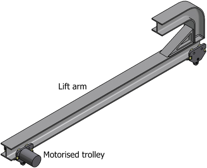
Lift arm with a motorized trolley
The control unit is responsible for data acquisition from the sensors in the spools unit, sending commands to the actuators in the lift arm and the spools units and communicating with the robot inside the silo.
The

Cleaning mechanism
The cleaning tool is connected to the end effector through a passive revolute joint. It consists of a central body and two arms holding the distal ends of the two sets of pneumatic nozzles. The two arms are connected by a pivot joint with an angular shift of 180° between them. Using two sets of nozzles permits cleaning of the required strip of the silo's surface. The thrust force, which depends on the nozzles' type, will blow the build-up material off the silo's surface, and force the cleaning tool to rotate around the vertical axis of the end effector.
The working space of SIRO is defined by the space that it can clean; in another words, it is the space that the nozzle of the cleaning mechanism can reach in order to blow off the build-up materials. In Cartesian coordinates, the location of the nozzle is determined by the following equations: X = Rcosθ, Y = Rsinθ, Z = h. where R is the length of the cleaning arm 2≤R≤4m, θ is the rotation angle of the cleaning mechanism 0≤θ≤2π and h is the altitude of the nozzle inside the silo 0≤h ≤30m. Thus, the working space of SIRO is a hollow cylinder, as illustrated in Fig. 4.
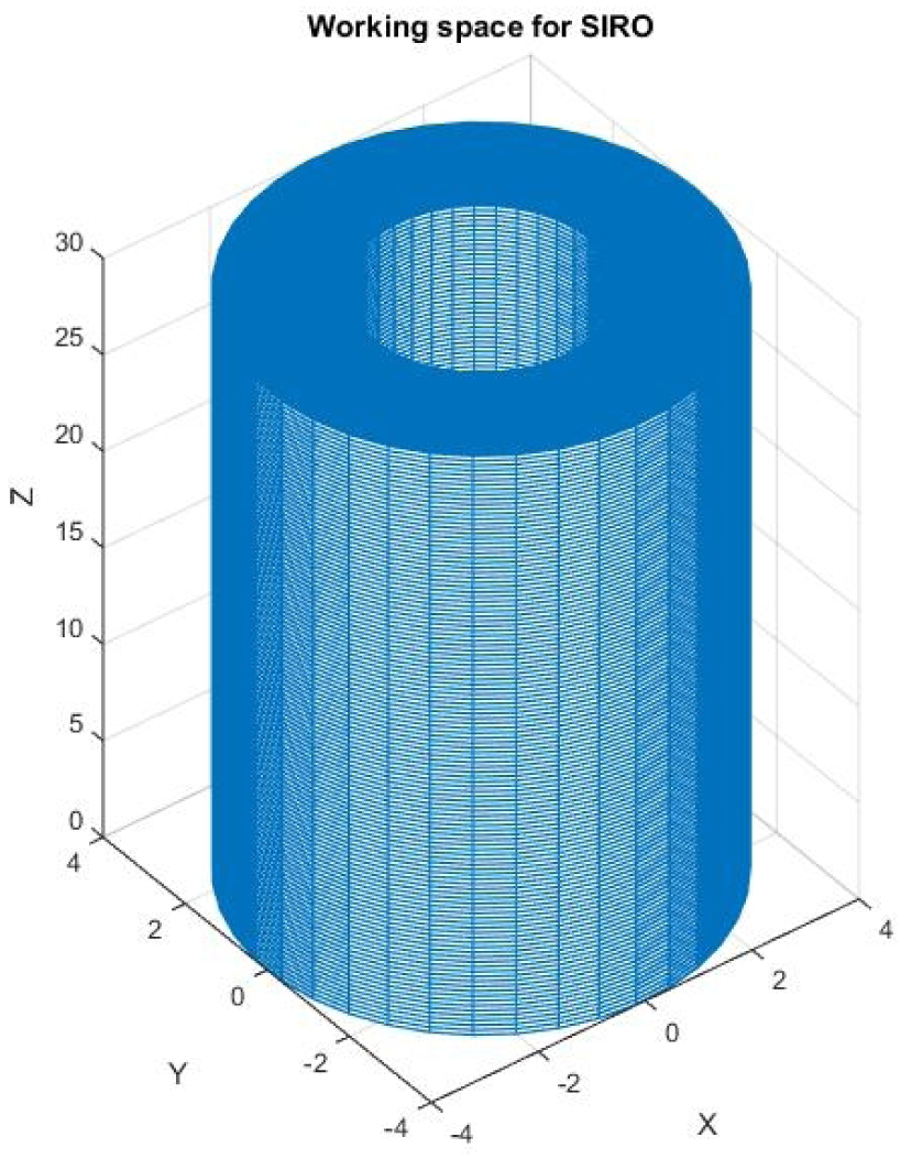
Working space of SIRO
2.2 Principles of the operation
Some details of the robot's kinematics are shown in Fig. 5. At the beginning, the robot is transported to the silo's roof in a folded configuration that is small enough to enter the circular manhole (diameter: 80 cm) (Fig.1 (a)). Then, after being attached to the suspension, the crawling and unfolding cables, the pneumatic hose and the control and power cables, the robot is lowered into the silo via these cables, which pass through the motorized trolley on the lift arm.

The robot's kinematics diagram
When the folded robot takes its vertical position inside the silo, the unfolding cable is released to unfold the six arms of both platforms and the two arms of the cleaning tool. They rotate down around their horizontal axes, about 100° through the passive revolute joints R1,R2,R3,R4,R5,R6,Rc1,Rc2, until all of them attain a full open pose, which is determined by shoulders on the central bodies of the two platforms and the cleaning tool.
The six prismatic joints T1,T2,T3,T4,T5,T6 permit the extension of the arms of the top and bottom platforms, and each joint is driven by a ball screw mechanism actuated by a DC motor. The arms extend until they achieve contact with the silo's interior surface. The appropriate degree of contact force and the arc shape of the robot reinforce its stability and allow it to hold a vertical position. A static structural analysis for SIRO is computed by the finite-element analysis software ANSYS. It shows that SIRO is statically stable when adequate force is applied through the ball screw mechanisms (F = 500N). These forces generate pressure forces on contact surfaces between the distal ends of the platforms' arms and the silo wall; the pressure forces give rise to friction forces that are capable of preventing the distal ends from sliding. A maximum contact pressure is noticed at the arms-silo contact surfaces (see Fig. 6(a)). Figure 6 (b) illustrates that the deflection is located on the level of the second segments of the platforms' arms, i.e., the arms maintain fixed points on the silo wall.

Static analysis of SIRO
After holding the position, the cleaning process starts by supplying the cleaning tool with pressurized air. Due to the orientation of the nozzles, a torque is created that forces the cleaning tool to rotate around the passive pivot joint Ref. By using a suitable rotary dumper, the rotational velocity of the cleaning tool is adjusted in order to make it appropriate for the cleaning process.
The vertical movement inside the silo space is achieved by a vertical crawling through the passive prismatic joints TP1,TP2,TP3. The crawling step is determined by the distance between the two platforms, which depends on the strip area that the cleaning tools must blow off. Crawling is performed by small, sequential retracting/expanding of the platform arms, followed by the sequential pull/release of the suspension and the crawling cables.
Figure 7 illustrates the crawling and cleaning processes of the robot inside the silo space. The bottom platform holds its position (Position K+1), where its arms still maintain the appropriate contact force with the silo wall. The top platform (in Position K) retracts its arms in order to lose contact with the silo wall and starts to move down slowly, along the linear shafts, through TP1,TP2,TP3, due to the gravitational force and by releasing the suspension cable. When the top platform reaches its new position (Position K +1), the (sc) is on hold and the platform's arms expand until they achieve contact with the wall. The bottom platform loses its position by retracting its arms and releasing the crawling cable; it then begins moving down slowly through TP1,Tp2,Tp3 to reach its new position (Position K+2), when the (cc) is on hold. The bottom platform holds its new position by expanding its arms until achieving contact with the wall. When the step down is completed, the cleaning process is activated in order to clean a new section of the silo wall.

Crawling movement inside the silo's space
Normally, the cleaning process is executed from the top to the bottom of the silo. All particles and removed material from the wall will fall under the influence of gravity and move away from the upper part of the silo that has already been cleaned. Therefore, when the silo's bottom is reached, cleaning is considered to be complete and both cables are pulled up in order to bring the robot to the top of the silo. Then, humans apply a dedicated procedure in order to remove the robot from the silo space.
3. Control-system architecture
The system is based on two hardware blocks: a robotic structure that moves inside the silo transporting the cleaning tool, and a support unit that comprises all of the hardware outside the silo that is required for providing support. Taking into account the fact that there is a physical connection between the cleaning robot and the support unit, the structure of the robot-control system is divided into two main parts: a

SIRO's control-system hardware
3.1 Robot-control subsystem
The major responsibilities of the robot-control subsystem (RCS) are driving the actuators and conditioning the signals and information from the robot's sensors. The DC motors that extend the robot arms are the only actuators in the robotic structure. In addition, there is a proportional valve for controlling the cleaning head's power. The subsystem contains different types of sensors: encoders, which measure the position and the speed of the motors and allow for real-time acquisition of the robot's kinematic configuration; force sensors, which measure the contact force between the arms and the surface; limit switches, which define the limits of the arms' movement and, finally, video cameras for controlling the quality of the cleaned surface. The core of the robot-control subsystem is a microcontroller unit programmed for required tasks. The information from the camera is not processed on board the robot; instead, it is sent as it is to the support-unit control subsystem.
3.2 Support-unit control subsystem
The support-unit control subsystem (SUCS) is responsible for controlling the motors in the spools unit and the motorized trolley, and for reading motors' encoders in order to calculate continuously the released length of the cables and traverse the distance of the motorized trolley. The hardware for the support-unit control subsystem can have a graphical user interface that allows the operator to have full access to the whole control process and to control the quality of the cleaning. The RCS communicates with the SUCS through a serial bus. Using RS-485 enables a high-speed data rate for a cable over 20 m long. The RCS sends the values of the encoders and force sensors to the SUCS, which are presented on the graphical user interface as the length of the telescopic arms, and the contact forces between the arms and the silo wall. Command notifications between the control subsystems, the RCS and the SUCS, are also sent through the RS-485; an example of this is when the RCS receives a command from the SUCS to extend the platform's arms after lowering the platform a step down.
3.3 Motion-control algorithm
Following the operating principles of SIRO, we can highlight three main tasks of motion control:
positioning the cleaning robot in the silo,
holding a vertical position during the cleaning process, and
achieving a vertical crawling motion.
The entire motion control process is activated after the cleaning robot with the cleaning mechanism has entered through the manhole into the silo's interior space. At the present stage of the project, the three tasks are separated with the option of a human operator switching each of the tasks ON/OFF and making decisions on how to proceed at any given point during the cleaning process. The operator can also operate the machine manually and monitor all individual motions. This is necessary for the tuning and debugging of both the entire SIRO system and its separate elements. Therefore, the operator interface is not as fully developed as it should be in its final, user-friendly shape.
A flowchart of SIRO's motion control is shown in Fig. 9. The task positioning of the cleaning robot inside the silo is fully performed by the SUCS, and the two other tasks are executed cooperatively by the SUCS and the RCS, which coordinate their commands through the serial link.

SIRO's motion-control flowchart
The entire SIRO motion-control algorithm is explained below
After attaching the folded robot to the cables and the pneumatic hose, the operator resets the length of the cables through the graphical interface in the SUCS, and lowers the robot into the silo by driving the spools' motors (Msc,MccMucMpc,Mph = ON in a CW direction). When the released lengths of sc,cc, uc pc and ph are equal to the required distance between the robot and the silo roof, which is equal to 1.5 times the length of a folded SIRO, the corresponding motors turn to the OFF state. The operator brings the robot to almost the geometrical centre of the silo by driving the motorized trolley and the spools' motors synchronously (Mt,Msc,Mcc,Muc,Mpc,Mph = ON in a CW direction). When the motorized trolley traverses the required distance in order to reach the geometrical centre, all motors are tuned off. To unfold the arms, the operator turns only Mcu to ON (CW) until all arms rotate down under the influence of gravity to their final positions, which are detected by limit switches; at that moment, Mcu = OFF. The role of uc is finished, so it is disconnected from the arms and pulled out of the silo. When the robot is in its unfolded pose, the RCS communicates with the SUCS in order to let the latter drives Msc,Mcc,Mpc,Mph achieve an ACW direction, so they can pull up the unfolded robot to the highest position inside the silo.
When the robot reaches the highest position, the RCS receives a signal from the SUCS to start driving the DC arms' motors (arms ‘motors = ON in a CW direction). Each arm extends until it is either extended fully (determined by a limit switch) or it touches the silo's wall (determined by a force sensor), arms' motors=OFF. The RCS optimizes the lengths of the arms so that they are equal, and allows all arms to make contact with the silo's surface. After touching the surface, the arms' motors are driven to apply appropriate contact forces Fcontact to the silo's wall as measured by the force sensors.
The RCS starts the cleaning process by activating the proportional valve, using proportional valve permits in order to achieve a smooth start for the cleaning task and to have the appropriate air pressure blow off the build-up material. The duration of the cleaning of a cylindrical surface strip is predefined by the operator; when the end of that period is reached, the RCS disables the proportional valve. The cleaning quality of the cylindrical surface strip is monitored through the video cameras that are fixed to the three arms of the top platform. If the operator is not satisfied with the cleaning quality, he can intervene and stop the control program, and force the robot to repeat the cleaning process in order to re-clean the contaminated strip.
After finishing the cleaning process, the RCS starts driving the DC motors of the top platform's arms (arms' motors=ON in an ACW direction), which retract at about 1% of its actual stroke (calculated using encoders), when reaching the retraced distance arms' motors=OFF. The RCS communicates with the SUCS to release the suspension cable (sc) (Msc = ON in a CW direction) one step down. When the step is achieved, Msc = OFF and the RCS drives the arms' motor of the top platform in order to hold its position (arms' motors=ON in a CW direction). The same process is performed by the RCS and the SUCS for the bottom platform's arms and cc,pc,ph in order to move the robot a step down and hold its position. After the crawling step is complete, the control system repeats the cleaning process and the crawling movement algorithms successively, until the whole interior surface of the silo is cleaned.
3.4 Scaled prototype
A scaled low-cost laboratory prototype of SIRO is designed and manufactured in order to evaluate the concept, and to test different types of locomotion. The silo wall and the cleaning mechanism are not implemented or installed at this stage of the work. The prototype consists of two platforms, six one-stage telescopic arms, linear bearings and shafts and a set of steel cables.
The two platform are positioned over each other with an angular shift 60° around the vertical axis. The top and bottom platforms are attached to the suspension cable and the crawling cable, respectively, and the arms are attached to the unfolding cable. Each of the ‘sc’, ‘cc’ and ‘uc’ should be able to bear the weight of the prototype (10Kg) and, considering that the safety factor is 10:1, choosing 1×7 stainless-steel strand with a diameter of 1.6 mm and a breaking force of 227 Kg will be appropriate for these cables. Each cable is wrapped around a spool with a diameter of φ = 20mm by a DC motor with a planetary gearhead. Three identical DC motors with gearheads that are installed in the prototype fulfil the minimum requiremerits: an output torque M = 3N.m, a radial shaft load of 100 N and the rotation speed of n=40rpm. Each platform comprises three pivot joints with an angular shift of 120° between them, where the arms are connected to these joints.
The telescopic arm consists of two segments that have square profiles; the dimension of the outer segment is 4 × 4 × 50cm and the inner segment is 3 × 3 × 40cm. Extension of the telescopic arm is achieved using ball-screw mechanisms driven by DC motors attached to the bottom of each arm. Two limit switches are fixed on the arm in order to define the lower and higher limits of the stroke, which is 25 cm. The force sensors are not installed on the arms, since the silo wall is not constructed in this stage of experiments.
The prototype control system comprises the robot's control system and a simple support-unit control system. It is a very simple system consisting of an ON/OFF control for the different actuators. This control system is built to achieve the first task of the robot, positioning inside the silo, and to verify the crawling movement. The RCS is built on an Arduino Mega 2560 micro-controller, and fixed onto the bottom platform. It is responsible for driving the motors of the telescopic arms and acquisition of the signal from the limit switches. The SUCS, in this stage of the test, is composed of a simple control card comprising a combination of switches and relays that drive the DC motors of the steel cables' spools.
The lowering of the folded robot, the unfolding of its arms, and moving it to the highest position using sc, cc and uc cables is shown in Figure 10. While demonstrating the arms' rotation, a distinct oscillation is noticeable, which corresponds with previous theoretical study [18]. Figure 11 shows the crawling movement of the prototype. It demonstrates the capability of the robot to move vertically inside the silo, which is achieved by the sequential release of the platforms' cables. The experiment shows the smooth transition movement of the two platforms along the vertical axis. Accordingly, the cleaning robot will be stable during crawling when support points exist between the distal ends of one platform's arms and the silo's wall. Carrying out the robot's other tasks for a complete test of its whole functionalities remain for future work.

The prototype in folded, unfolded and high positions

The crawling movement of the prototype
In summary, the robot is able to move up, down and to take a crawling step, and the control system operates successfully in order to provide the sequence of actions that the robot must take in order to achieve such locomotion.
4. Conclusion
In this paper, we describe the motion-control system of the SIRO robot for cleaning a food silo. Its mechanical structure has combined different concepts of robots that can operate in an elevated silo construction, while using a minimum number of actuators and getting maximum benefit from the force of gravity in order to achieve functionality. A number of experiments on a scaled prototype are ongoing, in order to verify various elements of the design and its overall performance in different simulated laboratory situations.
A distributed control system has been proposed for this robot, with two connected subsystems, one on the robot itself and the other on the support unit outside the silo. The motion-control algorithms for all three robot tasks, namely, positioning the cleaning robot in the silo, holding it in a vertical position and achieving a vertical crawling motion, are presented in this paper, which shows the responsibility of each control subsystem and presents the actuators and sensors that are used in the robot.
The design of a scaled prototype of the robot has been implemented and tested for basic functionalities: a vertical crawling movement and extension of the arms. The results were completely satisfactory and proved the correctness of the concept.
It is now the objective of current and future work to produce a final version of the SIRO robot, with all the designed subsystems that it needs to operate in a real silo environment.