Other
Select search scope: search across all journals or within the current journal


Of major interest to architects, designers of vehicles, and acousticians is the control of structure-borne sound. Walls and panels are set into vibration by airborne waves or by vibrating mechanisms. The panel so excited will radiate sound and it may carry the vibrations to other panels or bodies.
In this lecture, the author will treat the problem of acoustic transmission through walls and panels in the audible frequency range. At low frequencies the panel vibrates as a plate or a stretched membrane. At higher frequencies the panel may behave as a quasiinfinite sheet. Above a particular ‘critical’ frequency, the wavelength of the bending waves in the panel will be longer than the compressional waves in air at the same frequency. The two wavelengths may be brought into coincidence provided the airborne wave impinges on the panel at an angle θ determined by
cos θ =
where c a and
Measurements on plates, concrete sheets, and masonry walls will be presented and analysed. Analysis of the different types of response to airborne wave excitation will be made. Rules for the selection of simple and complex structures for buildings and vehicles will be suggested.
Means for reducing the response of structures to airborne wave and mechanical excitation include the use of damping materials in or on the structure, the introduction of discontinuities and the use of sound-absorbing blankets in the structure. Recent data on damping materials and means for utilizing them to produce maximum reduction of flexural waves will be presented. It will be shown that by proper utilization of such materials a structure-borne wave may be attenuated in a given distance by a factor of 10 or more than when utilized in a conventional manner.


The pressure required for certain extrusion and coining operations may be approximately estimated from a knowledge of that required to perform the analogous operations under conditions of plane strain, and these pressures may be closely over-estimated by the use of a principle due to Hill or a Limit Theorem of Drucker, Greenberg, and Prager. Numerous examples are presented of a graphical or primarily non-analytical approach for closely over-estimating extrusion or coining loads required. The solutions presented give insight into the mechanics of certain metal-working operations and give good approximate results for problems generally solved by the lengthy numerical procedures associated with the use of slip-line fields.
Part I of this analysis is devoted to solving the problem of bending a wide beam of ideally plastic material, under substantially plane strain conditions. A geometric method of solution, in which the stress and strain paths during the deformation are determined in the stress plane, is compared with the well-known analytical solution. Curves are given which will allow the rapid estimation of bending moments and ‘spring-back’ for plates of an aluminium alloy conforming to B.S. 1476:HE 15W†. The system of residual stresses induced is determined and compared with that for a narrow beam.
In Part II the geometric method mentioned above is used to estimate the effectiveness of stretching in reducing residual stresses which are transverse to the direction of stretching. This is a problem of some technological interest in that residual stresses arising from operations such as heat treatment and quenching are usually complex, lying in all directions within the plane of the plate. It is shown that stretching in a direction transverse to the major residual stresses is almost as effective in their reduction as stretching in a parallel direction.

Light-alloy castings can already be produced to consistently close limits by well-established die-casting methods, so the post-war developments of precision moulds are of more benefit to the other non-ferrous and ferrous foundry industries. Furthermore, the special light- alloy foundry techniques, the heat treatment and other processes, and the free-cutting properties of light alloys should be related to design and costs of production.
Test-bar specifications for a number of aluminium and magnesium alloys are given, and are discussed in relation to strength and weight of castings, and also to certain features of design, and to the cost of a machined casting in cast iron and various light alloys.
High-tensile steel bolts are necessary to shear screw threads in light alloys, and results of tensile tests on inserts and fastenings are given, together with estimates of cost of each method of assembly.
Where inserts and fastenings are used, precautions to avoid galvanic action between dissimilar metals are necessary only on exposed junctions, whilst for corrosion generally, precautions are just as necessary for the common light alloys as for the common iron and steels.

Experimental measurements are described of the load-deflection relations for rubber blocks having a wide range of thicknesses and varied shapes of cross-section. An approximate theoretical treatment is presented for classically small compressions of circular discs and infinitely long rectangular bars. The measured stiffnesses for small compressions are shown to be in good agreement with the theoretical predictions for a vulcanízate containing no carbon black, and, when an empirically obtained modification is made for thixotropic effects, for vulcanizates containing various quantities of carbon black. The behaviour under moderately large compressions is also examined.
A model of a band-reinforced, cylindrical, reactor pressure vessel has been manufactured and tested. The vessel dimensions were 5 ft inside diameter by 9 ft overall length, with hemispherical ends, nominal plate thickness being 1 in. throughout. Hoop reinforcement on the barrel consisted of 3-in. wide circumferential bands, each band being built up of 13 layers of
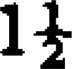
-in. strip, giving a total band thickness of 1
in. Full details of design, construction, and method of manufacture are given.
A complete experimental investigation into the stress distribution in the vessel has been carried out, using electrical resistance strain gauges, both at its design pressure of 1000 lb/in2 and also at twice this pressure. The stress distribution on the inner surface of the barrel, on the outer surface of the bands, and local to the tangent line has been measured. These results are compared with theoretical calculations.
Finally, the vessel was pressurized to destruction.
The results show that, as would be expected, the band reinforcement was not fully effective. However, the general stress level was maintained within acceptable limits, the theoretical stresses being exceeded by about 20 per cent. The bursting pressure of 3940 lb/in2 confirms the safety of the design, that is, a design factor of safety of 3·94.
It is considered that the results of the investigation fully demonstrate the safety and merits of the design.

As part of a programme of comparison of filmwise and dropwise condensation of steam, it was required to know the effect of a cross flow of steam, with some non-condensable gas present, over the condenser tube. A 'steam tunnel' was developed in order to produce the required steam velocity with a limited steam supply at atmospheric pressure. Details of the apparatus are given together with the results of tests on a vertical tube.


This paper describes the design and development of a pneumatic extensometer suitable for the measurement of axial strains of the order 10-5 over a range of ±20 per cent, using a 1-in. gauge length.
The pneumatic gauge is capable of measuring strains less than 10˜-5 over a range of approximately 4 times 10-3 thus ensuring adequate measurement of elastic and initial plastic strains. A micrometer screw is used for adjustment to cover the large range and is suitable for measurement of gross plastic strains. The mechanism of the instrument was designed to comply with the following requirements:
magnification linear with strain, nozzle and micrometer spindle to be maintained parallel, insensitive to bending strains, and accommodate changes in specimen diameter without adjustment.
Consideration of these requirements led to the choice of a parallel-motion mechanism made in two halves to allow for changes in specimen diameter. The measuring units were so placed as to measure the mean strain between the gauge points.
The method of calibration is described and also the method for analysing the results for comparison with the theoretical expression derived. This calibration and subsequent use of the instrument have shown that all the requirements listed above have been adequately satisfied.
The cold working of high-strength metals and alloys into sheet and strip form at the thinner gauges allows the metal manufacturer two alternatives: (1) high capital expenditure on a specialized mill of the Sendzimir or planetary type or (2) where demand does not justify the capital outlay, the application of new techniques utilizing existing equipment. In the latter class, the method of sandwich rolling is examined by theory and by experiment and it is shown that reductions in load up to 60 per cent can be achieved for rolling thin hard strip. The method allows greater reductions than for rolling the metal alone and decrease in finished thickness is obtained.
A method of adapting current cold-rolling theory for the calculation of loads involved in planning production schedules is set out, based upon a criterion of simultaneous yielding in the hard and soft metal layers. Optimum conditions of metal thickness ratio and hardness ratio for the sandwich metals are discussed.

The paper considers the inherent non-linear effects of inertia load on the performance of a pilot valve and ram system. Such a system may be considered as a model for many valve and ram or valve and motor combinations which are found in hydraulic control systems, and the results are therefore expressed in generalized form. It is shown that cavitation can occur dynamically when linear analysis would predict that only l/√2 of the static stalled effort is being utilized. Prior to cavitation there is surprisingly little distortion and attenuation of the velocity wave form of the ram when the valve is moved sinusoidally. The beneficial effects of exhaust lap are discussed and the paper goes on to develop and qualify the analysis when compressibility, friction, leakage, symmetrical lap and dither are introduced. Experimental results are compared with the theoretical predictions and the paper includes a note on the validity of small perturbation theory for this type of problem.
When a hydraulic servo controls the position of a load the force required to move the load is produced by a pressure drop across the actuator. This pressure drop decreases that available to drive fluid through the control ports of the valve with the result that the speed of response is reduced.
This paper examines the effects of various types of load on the dynamic behaviour of the system for both step and sinusoidal input signals.
Analytical solutions to most of the response equations are obtained but graphical methods are occasionally used. When an inertial load is present it has been found necessary to consider the step response in the velocity-displacement or ‘phase’ plane.


General expressions are obtained for the stress distribution in an infinite flat plate end- loaded by equal principal stresses and containing a circular hole reinforced by a compact ring. The ring reinforcement being placed on one side of the plate only so that the other side of the plate remains flush.
It is shown that the effect of an asymmetrically placed reinforcement is to induce in the plate and reinforcement bending stresses which are not negligible compared with the externally applied direct stress. Furthermore, from particular examples considered, it is found that reinforcements having practical dimensions can give rise to stress concentrations in the same order of magnitude as those in a similarly loaded plate containing an unreinforced hole.
Thus, a reinforcement designed to satisfy B.S. 1500:1949 has a small compensating effect compared with a symmetrically placed reinforcement having the same cross-sectional area.
For practical purposes, data have been obtained which enable the designer to determine quickly the stress distributions associated with reinforcements and plates having a reasonably representative range of dimensions.
This paper reports a study of the vibrations of pre-wisted cantilever blading. The blading is pre-twisted linearly about the centroid of its cross-section up to an angle of π/2 rad and is considered to be mounted encastré at the root. Accurate prediction of the frequencies of vibration of such blading is of considerable practical importance.
Two theoretical approaches to the problem are discussed. The first one, involving a direct solution of the equations of motion, is not made use of, although the characteristic equations are derived in an appendix for reference. The second approach is based on the application of Rayleigh's principle. For blades of uniform rectangular cross-section, frequency equations are derived for the fundamental mode of lateral motion and all the modes of torsional motion. Similar types of equation are shown to apply to aerofoil cross- section blading since direct coupling effects between bending and torsion, being extremely small, can be neglected.
Vibration tests were conducted on sets of blades of both uniform rectangular and uniform aerofoil cross-section pre-twisted between 0 and
For the modes of motion where a theoretical solution is provided, reasonable agreement is shown to exist between the calculated and corresponding measured frequencies. Hence, the use of Rayleigh's method is justified, giving, as it does, relatively simple expressions for the natural frequencies of vibration.
The torsional frequencies of pre-twisted blades are dependent on the torsional stiffness values. Hence, a theoretical study of torsional stiffness variation with pre-twist is presented, the results obtained being confirmed experimentally by a series of simple torsion tests.
The paper describes an investigation of the effects of piston-excited pressure waves in the plain induction pipe of a small, high-speed, single-cylinder air compressor. For a range of pipe lengths and diameters, compressor speeds and delivery pressures, the observed compressor throughput and driving torque are compared with those obtained with no intake pipe fitted. Based on classical laws of wave motion but using an experimentally obtained steady-flow characteristic for the inlet valve, a theoretical treatment is developed to describe the pressure pulsations in the inlet port and cylinder and to predict the change in airflow resulting from the fitting of any particular intake pipe. Experimentally recorded indicator diagrams compare satisfactorily with those predicted theoretically and similar agreement is obtained between the experimental and theoretical values of airflow. An 18 per cent increase in airflow is reported.

This paper deals with certain aspects of the tube-expanding process, which have been investigated using the test rig previously developed as part of a research sponsored by the British Shipbuilding Research Association.
The factors investigated are (1) retubing, (2) the starting position of the roller cage within the tube, and (3) the initial clearance between tube and seat. A few tests are also reported on the relaxation of the joint with time.
In the retubing tests, further tubes were expanded into seat plates used in previous tests, from which the original tube had been removed. The main conclusion was that seat pressures can approach the theoretical maximum in retubing, and that if an extra pass is made to take advantage of the work-hardened seat, a stronger joint than in a first expanding results.
To study the effect of the starting position of the rollers within the joint, four complete tests were made. The results show conclusively that a much stronger joint is obtained with less work, if the rollers start with their front ends almost at the back of the joint.
Tests to study the effect of the initial clearance between tube and seat showed that clearance is not a major factor in joint strength.

Experimental apparatus has been developed and used to study the friction characteristics of an externally pressurized air-lubricated journal bearing. The effects of variations in speed, load, diametral clearance, and inlet pressure have been studied over a wide range at high speeds. The experimental friction coefficients have been compared with those given by the well-known Petroff (1)† formula, and a reasonable degree of correlation has been found.
Bearing air consumption has been measured and a linear relationship between air-mass flow and inlet pressure is indicated. Curves relating load-carrying capacity to various ratios of inlet pressures are included, the applied loads being carried by hydrostatic flotation in all cases.
The bearings used were plain, cylindrical bushes of diameter
in. and length
in. Compressed air was admitted through three sets of radial-inlet holes around the bush circumference, pressures being adjusted to keep the shaft and bush as close to concentric as possible.

This paper is divided into four sections dealing with the response (both velocity and displacement) of a loaded hydraulic relay to Part I step function, Part II ramp function, Part III sinusoidal input, and Part IV general input. In Part IV equations of motion are developed for any variation of the input valve and these include a viscous-damping term and first-order contributions due to oil compressibility and leakage past the ram. The relay with feedback linkage is treated and parameter limits are established for normal (cavitation-free) motion. The remaining sections analyse the system in turn for the various inputs by solution of the equations of motion, but with increasing restrictions. In Part II methods are given for extending the case to linear closing of the valve and a delta function input. Valve overlap is briefly introduced in Part III. Cavitation criteria in terms of general non-dimensional parameters are developed in all sections. Many results are presented graphically or in tabular form, the mathematics being reserved for appendices whenever possible.
A narrow-faced, bolted, flanged joint is a highly complicated stress-system. When internal pressure is applied, the stress-system changes. In order to establish, quantitatively, what these changes are, a series of experiments were carried out on a pair of
-in. nominal bore screw-on hubbed flanges.
The apparatus was assembled as shown in Donald and Salomon (1, Fig. 1)† An accurate measure of bolt stress and, hence, the stress on the gasket was obtained by attaching a total of four electric resistance strain-gauges to two ‘measuring’ bolts. As the nuts were all tightened carefully by means of a torsion wrench, an average of the readings of the four gauges gave the average bolt stress of the eight bolts.
Care was taken that the gauges were cemented to diametrically opposite sides of the bolts and that two of the gauges were pointing toward the centre of the flange while the other two were pointing in the opposite direction. From the readings of the two pairs of strain-gauges, it was possible to calculate the extent of bending of the bolts during application of internal pressure and, hence, the rotation of the flange-rings due to pressure. The results of the experiments indicated:
There is a linear relationship between bolt load and internal pressure. The slope of the line giving this relationship depends on the elastic properties and the dimensions of the components of the joint. This slope can be predicted mathematically. This slope can, in the case of pseudo-elastic gasket materials such as compressed asbestos composition, be positive, negative, or zero; the slope in any particular joint depending only on the initial load on the gasket.
The rotation of the flange rings due to pressure increases as the slope of the bolt load The rotation, as calculated from strain-gauge measurements agrees fairly well with that calculated by use of the theory of Wesstrom and Bergh. The circumferential strain in the flange and pipe assembly is at a maximum in the pipe at the back of the hub. This result is in agreement with that reported by several other investigators and is not discussed in this paper.

The investigation described in this paper consists of three parts. Part I is concerned with an experimental investigation of the vibration of vertical milling machines under test conditions. It is shown that in the frequency range investigated, 6-10 000 c/s, the machine structure has five modes of vibration which responded with large amplitudes. The dynamic deflections corresponding to these are discussed and attention is drawn to certain structural weaknesses frequently encountered in vertical milling machines. Part II of the paper reports various experiments concerned with face-milling chatter. It is shown that the severity of chatter depends on the relative position of cutter and work-piece and the depth of cut. When the depth of cut exceeds a certain minimum value, the machine chatters in definite speed bands which are separated by chatter-free speeds. As the depth of cut is increased, the chatter-free speed bands contract. From this and the variation of the chatter frequency, it is concluded that the chatter observed is of the regenerative type, similar to that arising in the case of drilling and other machining processes (1), (2)†. A theoretical interpretation of the experimental results is given in Part III. Chatter behaviour of the machine is discussed with the aid of a three-dimensional stability chart. The constants required for the construction of this chart are extracted from the experimental results given in Part II. Correspondence between theory and experiments is satisfactory.
A theoretical and experimental study of the discharge from an engine cylinder to atmosphere was made. The objective of the work was to establish suitable data for the design of exhaust ports. Two theoretical methods were used, in the first method the discharge was analysed by the method of characteristics and it was shown that the discharge was by wave action. The second method neglected the particle velocity in the cylinder. Comparison of the latter method with the solution by characteristics showed good agreement over the main part of the discharge and it was possible by that method to develop a simple design formula for the estimation of the port area.
The experimental investigation was carried out on a special machine which simulated in all respects the exhaust-port arrangement of a two-stroke cycle engine. The machine was designed to investigate the effect of port configuration, port timing, cylinder length, engine speed, release pressure, and temperature. By suitably arranging the variables in non- dimensional groups a wide range of engines could be simulated. The flow characteristics of the exhaust ports were examined under both steady and unsteady flow conditions. The following conclusions were drawn: (1) the coefficient of discharge for the exhaust ports increased with cylinder pressure and decreased with increased port area, (2) the coefficient of discharge was lower under dynamic conditions than under steady flow conditions, (3) the dynamic coefficient of discharge decreased with reduction in cylinder length at release, (4) the effect of early port opening was to reduce the blowdown time, (5) the effect of piston movement during discharge was to reduce the effective port area required.

This paper gives a theoretical method of calculating the aerodynamic forces on vibrating compressor and turbine blades subject to two fundamental limitations. These are, firstly, that the time for the fluid to flow through the cascade must be small compared with the period of the vibration, and secondly, that adjacent blades must vibrate nearly in phase. This enables any kind of two-dimensional steady-flow cascade data to be used. The methods given also allow the vibration forced by fluctuations in the incident flow to be calculated.
The main conclusions are as follows:
Bending vibration of unstalled blades with small mean deflection is always damped. A criterion for bending flutter of unstalled blades with large mean deflection is derived. This is qualitatively supported by experiments carried out by Shioiri and Shibata (1)†. A condition of instability of the flow through stalled cascades of fixed blades is derived, and agrees with previous investigations by Fabri and Siestrunck (2) and Rannie and Marble (3). This also agrees with the results of an experimental investigation by Wood (4). A criterion for the bending flutter of stalled blades is derived, and it is shown that this limit is reached before the instability limit referred to in (3) above. It is found that, except for a particular case of zero stagger cascades, flutter of unstalled blades in torsion will always occur. For this case, however, the first fundamental assumption referred to above is unlikely to be true and more detailed investigation of this case is required.
In this paper is discussed the application of some of the concepts of modern control theory to the problem of the governing of compression-ignition engines. A physical description of the problem is given, illustrated by measurements made on governors and engines, including some to show the effect of the finite-time intervals between successive firing strokes, and other non-linearities such as Coulomb friction. In Appendix I is discussed the setting up of the equations of motion of mechanical systems, and their solutions using vector methods and the inverse locus to find the stability and also the transient responses of the system. While none of the theory will be novel to control engineers, part of its presentation may be. Some experimental data obtained on medium-size engines are included, together with comments on their use and some details on the investigation of unstable engine-governor systems. A large saving in test-bed time is reported.
This paper is restricted to a review of the work carried out in order to develop a strain gauge capable of operating at temperatures up to 1000°C with an inherent accuracy of ±5 per cent.
A large number of resistance alloys were tested as unbonded long wires at room temperature and, from the results obtained, a small number were selected for further investigation, in the form of gauges, at high temperatures. The effects of factors such as metallurgical changes, geometric shape and long-term exposure on the behaviour of the gauges were investigated. A number of bonding mediums, some commercially available, were examined with particular reference to creep under load, shear strength and resistance to erosion and thermal shock. Finally some preliminary tests in conjunction with the measurement of steady strains at elevated temperatures were undertaken.
It is concluded that the gauge factor is a function of the lattice imperfections of the element wire and, as such, will be temperature-conscious only if the imperfections themselves are affected by temperature variations. In general, any factor affecting the resistivity will affect the sensitivity. The most significant result obtained during the work described is that the gauge factor may be predicted within ±5 per cent at any given temperature, provided certain precautions are observed.
Some typical failures under field conditions are discussed as also are the possibilities of operating for protracted periods under steady stress conditions. More stringent requirements for future applications suggest that the wire gauge will be unsuitable, in view of its low resistance in very small sizes, and a possible alternative is briefly outlined.
In an attempt to overcome the deficiencies of existing theories of cutting, an experimental technique was developed for observing the cutting process during slow orthogonal cutting of mild steel. An attempt to find consistency between the observations and the ideal theory of plasticity failed. Consequently the theory was extended by including the effect of work- hardening and, in spite of the laborious nature of the analysis, it appeared that consistency had been regained. This led to a novel and physically consistent picture of the cutting process, which was taking place during the tests.
The paper presents a study of the flow in spray holes of 0.2 to 2.5 mm diameter and shows how the changes in cavitation pattern affect the appearance of the jet. The influence of the cavitation number, Reynolds number, the upstream edge sharpness, and the length/diameter ratio is investigated.
A cavity first formed near the upstream corner, but soon caused the jet to leave the wall altogether so that only the upstream corner had any effect on the flow. Under noncavitating conditions the emerging jet had a ruffled appearance, but under conditions when the jet had left the wall, it emerged smooth and glass-like. The glass-like stage could only be obtained with very accurately made spray holes, and any disturbance upstream, such as occurs in actual Diesel nozzles, caused the jet to appear ruffled at all times.
The discharge coefficient was found to vary with Reynolds number and cavitation number and a contour map covering Reynolds number of 1000 to 20 000 and cavitation number of 0·2 to 100 is presented.
This paper deals with the variation in discharge of small submerged orifices used in aero-control systems. It is shown that the effects of cavitation can be high and can cause changes of discharge coefficient greater than those associated with Reynolds number when the flow is turbulent.
The orifice length was altered and it was found that the most unstable conditions occurred when the length was half the diameter.
Further tests were carried out with inlet chamfer in order to determine the optimum angle and depth of chamfer for cavitation suppression.
While tests were being carried out on the motion which follows sudden closure of a valve at the beginning of a pipe, certain irregularities of the ensuing wave trains were noticed. Such irregularities were brought out all the more clearly because a sensitive electronic recorder was used. The special experimental arrangement prevented the appearance of these irregularities, henceforth called secondary waves, during the first surge, which helped considerably the theoretical exposition. However, they were later superimposed on both the negative and positive surges. The reasons, which are not entirely different in both instances, are the main subject of discussion in this paper.
An analysis is given of a thin, constant-thickness, circular plate subjected to uniform lateral pressure. The plate is assumed to rest on an elastic foundation and to be elastically restrained at the edges against rotation and vertical deflection. The equations for the magnitude and location of the maximum stress in the plate were programmed for an electronic computer and curves obtained for both these quantities for various values of two dimensionless parameters. These curves are presented in the paper and it is shown how the optimum design of a constant-thickness circular plate can be quickly effected with their aid.
One interesting result of the analysis is that it is possible to design plates in which the maximum stress is between 25 and 50 per cent smaller than that in similar plates with simply supported ends. This possibility does not appear to have been appreciated before and its utilization has obvious economic advantages. Another result of interest is that the value of the dimensionless elastic rotational restraint parameter giving minimum thickness is almost a constant for most cases occurring in practice.
A brief discussion is also included of the application of the curves obtained for homogeneous plates to the design of perforated tube-plates.

The frozen stress photo-elastic technique was used to determine the peak stresses occurring in rotating discs which represented rotor sections. A large range of shapes of winding slots was tested and a simple empirical relationship was obtained from which the peak stresses at the necks of the teeth can be readily calculated. It was shown that these results are directly applicable to steel rotors.
Semicircular subslots (inward from the winding slots) and interslots (between the winding slots) reduced the peak stresses. The largest possible cooling slots with semicircular roots are recommended.
The stresses in the tips of the teeth due to the thrust of the winding-slot wedges were studied with static models in which the centrifugal force due to the windings was replaced by a tensile force. From these results recommendations were made for the least highly stressed shapes of tooth tips in rotors containing interslots.
Operating difficulties encountered with a deaerating feed heater during full-scale test-bed trials of a complete prototype main propulsion machinery installation are described, together with the eventual successful remedy. The water level control system of the deaerator is analysed mathematically and a criterion for stable operation established. Comparison of the theoretical and observed behaviour of the deaerator shows reasonable agreement. Practical factors affecting the validity of the theory are examined and suggestions made for improvements in design. Some remarks on common deaerator design practices are made in the light of test-bed experience.
The example of this deaerator is used to illustrate an introduction to more general analytical methods. The need for these in modern steam-plant design work is explained, together with the obstacle to their use imposed by our current ignorance of the kinetic characteristics of common plant items.
The terminology of three-dimensional projection is examined and axometric projections compared. A method is introduced which enables a pictorial view to be drawn from orthographic views without using direct projections or special set-squares.
This paper describes a fundamental experimental investigation of heat transfer by free convection in a static heated tube, sealed at its lower end, and arranged so that the inclination of the tube to the vertical can be varied. Heated fluid adjacent to the tube wall forms an annulus which is discharged from the open end into a suitably cooled large reservoir, while a central core of cool fluid is continuously drawn into the tube by way of replacement. The case of the vertical tube under both laminar and turbulent flow conditions has been previously studied (Martin (1)†) and the present work continues the investigation of the system.
Inclination of the tube sets up a secondary acceleration normal to its principal axis. The pressure gradients which are thereby induced should assist the circulation of fluid from the cold to the hot stream, thus reducing the thickness of the annulus and increasing the area of the core. The increased effectiveness of the system might then be expected to improve the heat-transfer rate. This is found to be true in laminar flow (of the boundary layer type) except for small tilting angles. The weak secondary pressure gradients which then occur are believed to be responsible for mingling of the fluid particles on the common boundary, and this reduces the heat transfer. The same general trends are apparent even when there is some degree of turbulence in the system.
The stable turbulent regime is not of the boundary-layer type, because of the tendency for the cool entering fluid also to become turbulent, but what is called fully mixed flow, where the two turbulent streams mix. This causes reduced circulation and heat transfer. Under these conditions sufficient tilting of the tube eventually brings about the elimination of the mixing effect and a more efficient transfer of fluid particles between the two streams. The greatly increased heat transfer appears to be consistent with a stable turbulent boundarylayer flow regime, which, if attained, would improve the effectiveness of the open thermosyphon as a cooling device for both nuclear reactors and gas-turbine rotor blades.

When a ball rolls between two surfaces, in general, a tangential contact force and a relative angular velocity of spin are present at each point of contact. Both these actions give rise to tangential frictional tractions transmitted across the contact surface which are shown to result in a velocity of creep of the ball in a direction perpendicular to the nominal rolling path.
The magnitude of the creep velocity depends critically upon the magnitudes of the tangential force and the velocity of spin. If these actions are small there is negligible slip between the contacting surfaces and the creep motion is predominantly a function of the elastic properties of the materials. At larger spin velocities slip extends over a greater proportion of the contact area and the creep is influenced by the frictional properties of the surfaces.
Creep measurements have been made over a wide range of conditions of rolling. The results are reduced to non-dimensional form, in terms of two parameters expressing the effect of tangential forces and spin respectively.
The resistance to rolling has been measured and is shown to control the axis about which the ball rolls. The detailed mechanism of the rolling process is discussed.
Fatigue tests have been carried out on mild steel specimens containing edge cracks of various lengths and the alternating stress just insufficient to cause the cracks to grow obtained. It was found that the relation between this critical alternating stress σ and the crack length
The basis of a simple rational method for the analytical determination of discharge coefficients for the rounded-entrance nozzle and Venturi, covering the entire Reynolds number range, is presented. Certain experimental results, when compared with the theoretically derived curves, support the method. Tentative explanations are given, with the aid of the theory, for a number of puzzling and disturbing features arising from the results of some recent flowmeter calibrations. The analysis includes a new method of plotting the discharge coefficient against Reynolds number, which greatly facilitates the interpretation of experimental data.
Centralized control of a compression plant, in which the speeds of a number of large compressors are remotely controlled by pneumatic means, has been in full operation since 1955.
In this paper are discussed the principal design features leading to the choice of pneumatic equipment, the application of which is illustrated by detailed descriptions of typical machine installations. Descriptions of the control-room layout and the means adopted for ensuring reliability of the compressed air supply are also included.
The paper concerns the hydrodynamic turbulent motion in the lubricant layer. Proceeding from the Reynolds equations and introducing the approximations currently used in lubrication problems, owing to the lubricant film thickness, the general motion equations for turbulent lubrication are written.
Using the Prandtl mixing length hypothesis, exact and approximate solutions are obtained for the velocity distribution into the lubricant layer. The results are discussed by pointing out the pressure gradient and the Reynolds number influence on the velocity distributions, as well as the differences with respect to the laminar flow.
In order to obtain simple formulae, the exact dependence of the rate of flow on the pressure gradient into a dimensionless form is replaced by a linear relation, the slope of which depends on the Reynolds number. This approximation allows the obtainment of the pressure differential equation under a simple form. The pressure equation is integrated in case of journal bearings, by assuming a constant or a variable viscosity of the lubricant.
The results are compared to the experimental data obtained by M. I. Smith and D. D. Fuller and the good qualitative agreement is pointed out.