Other
Select search scope: search across all journals or within the current journal


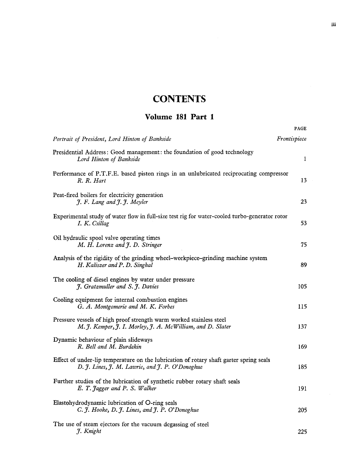
Published data on the wear of non-metals is usually based on tests using a sliding disc on a rotating drum, with atmospheric air surrounding the equipment. Although this type of test gives a fair indication of the relative merits of the materials, it is impossible to accurately estimate the wear of piston rings under working conditions. Tests have therefore been carried out on various filled polytetrafluorethylene (P.T.F.E.) materials in an un-lubricated reciprocating compressor. The materials were tested as piston rings with helium as the working gas. The gas was used in two conditions:
‘Wet’ where the moisture content was approximately 200 parts per million (p.p.m.) by volume. ‘Dry’ where the moisture content was approximately 7 p.p.m.
The fillers used were carbon, glass fibre and molybdenum disulphide and it was found that the carbon filled materials had the lowest wear rate in the wet gas. Using the dry gas the glass fibre filled materials gave the lowest wear rates.
All the materials showed a tendency to local decomposition of the P.T.F.E. to carbon and fluorine and this is thought to be due to local hot spots formed by the relative movement of the ring in its groove.
The Electricity Supply Board of Ireland has been using peat-fired boilers for electricity generation for over 15 years. Peat is produced in two forms—sod and milled. Sod peat is burned on chain-grate stokers in boilers of up to 20 MW capacity; milled peat is fired as pulverized fuel in boilers of up to 40 MW capacity. Total peat-fired plant is 407 MW.
Production methods for sod and milled peat are outlined. The paper describes the combustion technique adopted for these two fuel forms and the special maintenance and operational difficulties experienced over the years. The influence of peat characteristics on boiler design and the salient differences compared with coal and oil-fired boilers are explained. Details are given of performance and cost figures compared with coal and oil-fired plants.

The demand for electric power has doubled in the last decade. The most economical way to meet this demand is by building large-output generating units. The study of the major factors which determine the output of such generators shows that the only effective way to increase the output is by improving the cooling of their windings. For that reason design has progressed from air-cooling to indirect hydrogen-cooling, then to direct hydrogen-cooling. Now the trend is towards direct water-cooling where the water is in direct contact with the copper windings. The introduction of water into the stator winding was established in 1956 (
The introduction of water to a rotating winding presents difficult problems in both design and manufacture. The test rig dealt with in this paper was built to study some of these problems and to carry out experimental investigations on a full size model of the special hydraulic features for a water-cooled turbo-generator rotor. The investigations were concentrated around the following five different problems which are dealt with in detail: (1) increase in pressure drop due to rotation; (2) free-rotating seal (inlet seal) (
This paper concerns oil hydraulic spool valves of the on-off type and describes an investigation into the time taken for such valves to open or to close. Operating times depend upon the forces acting on a spool as it slides along the bore and the balance of these axial forces has been both analysed and studied experimentally.
Operating times were first estimated from a simplified equation neglecting forces due to fluid flow. Experiments were then made on two solenoid operated valves to measure actual times and to discover the reasons for differences between calculated and measured values.
Measurements of the sliding friction force between spool and bore indicated that the spools were never concentric in their bores but were displaced radially at all times.
Measurements and analyses were also made of the forces due to fluid flow through the test valves. These suggested that it is important to take account not only of momentum changes (
Another equation incorporating flow effects was then developed and shown to give a realistic indication of the behaviour of a valve. It is concluded that a simple form of equation may be adequate for approximate predictions of valve operating times, but that a more satisfactory method is to use the complete equation based on the work reported in this paper.
The purpose of the paper is to establish a relationship between the vibration marks generated on the work-piece periphery and the rigidities of the grinding wheel-workpiece-grinding machine systems. To investigate the problem several static and dynamic methods of determining the rigidity are analysed.
Based on experimental results the grinding machine is assumed to consist of two separate sub-systems: the wheel-head-body system and the workpiece holding system, both coupled together by the grinding wheel.
To check the correlation between various methods of determining rigidity, differential equations of motion have been introduced and solved with the aid of a digital computer. In order to consider all forces taking part during grinding an effective force factor has been analytically defined and applied to determine the rigidities. To find the relationship between rigidity established in static conditions and during grinding, coefficients of static and dynamic rigidity have been proposed.
Water cooling in diesel engines is studied, with particular reference to the application of these engines in locomotives of high power. In this context, problems relating to weight, volume and radiator design become progressively more difficult to solve with the tendency towards increased unit powers.
In the solution considered the water in the cooling system is put under a high static pressure, which makes it possible to raise the water temperatures above the usual levels. Resulting from this, the formation of steam bubbles is reduced or eliminated, ‘cavitation corrosion’ is reduced considerably, and cavitation in the water pump is prevented. Water consumption is markedly reduced. Standard equipment for locomotives is described.
Cooling the supercharge air and the lubricating oil at relatively low temperatures is compatible with cooling the engine at a high temperature if two cooling circuits are used, with their radiators placed in series in the cooling air current.
The case of cooling engines of high supercharge is examined; in these, the heat taken from the admission air and from the lubricating oil exceeds that taken from the engine.
Future designs of heating and cooling systems for engines with very high supercharge are proposed.
The several positions in engine fluid systems in which cooling equipment is commonly used are examined and the fluid pressures and temperatures to which the heat exchangers are subjected outlined. General considerations affecting the designs from the points of view of performance (heat transfer and power loss) and environment (chemical and mechanical) are examined and amongst other points it is shown that the best ratio of cooling surfaces in a secondary surface heat exchanger is
If ρ = 1 this reduces to
The second part of the paper is descriptive, and deals with the mechanical design of heat exchangers used for cooling engines in various applications: marine engines; stationary engines; locomotive and railcar engines; agricultural machinery; road vehicles; and aircraft.

In order to establish the necessary data to enable high proof strength austenitic stainless steels to be used for the fabrication of pressure vessels, plates were produced with an increased proof stress obtained by the warm working method. The laboratory investigation then showed that it was practicable to raise the proof strength of this material to twice the normal value for fully softened plate with an improvement in the ultimate tensile strength.
Following this, two similar experimental vessels were manufactured in normal and high proof strength 18% Cr-8% Ni-Ti stabilized steel and these were subjected to hydraulic pressure testing. The vessel tests showed how stainless steel vessels behave under static pressure application at room temperature, and the behaviour of the high proof strength vessel indicated that it would be quite safe at nearly double the design pressure for the fully softened vessel. The strain hardening of stainless steel, fabricating techniques and weld quality have also been investigated and these are reported upon in the paper. Proposals for design stress criteria and stress values are made in relation to an examination of existing pressure vessel codes and the experimental data.

The friction characteristics resulting from the motion of one surface over another form a very important facet of the behaviour of many physical systems. This statement is particularly valid when considering the behaviour of machine tool slideways. Most slideway elements consist of two plain surfaces whose friction characteristic is modified by the addition of a lubricant. In many cases the complete slideway consists of many mating surfaces and the choice of slideway material, slideway machining and lubricant is often influenced by the long term problem of wear. The aim of this paper is to present results of experiments on a test rig designed to be representative of machine tool slideway conditions; the experiments were wholly concerned with the behaviour of the bearing under dynamic conditions. The major emphasis is on results obtained with a polar additive lubricant which appears to exclude the possibility of ‘stick-slip’ oscillations. A parallel series of tests are reported where a normal hydraulic oil was used as lubricant. The use of this second lubricant allowed some study of the ‘stick-slip’ process. The dynamic friction characteristics, cyclic friction characteristics and damping capacity of several slideway surface combinations have been obtained and are discussed in the context of earlier work in the field and the role of slideways in machine tool behaviour.
Although rotary shaft garter spring seals are widely used throughout industry, very little is known about the sealing mechanism of the lip-shaft interface. It is now generally accepted that some sort of fluid film separates the lip and the shaft. Previous workers have also postulated a relationship between the coefficient of friction and a non-dimensional hydrodynamic parameter, as in standard lubrication theory. This present paper clarifies this relationship, and shows that seals can also operate over the mixed friction, as well as the full film lubrication region. The results were obtained by accurate knowledge of the operating temperature under the sealing lip. Two types of surface thermocouple were developed to do this and these are described in full.

The paper presents a theoretical solution to the ideal problem of an O-ring seal constructed of an isotropic elastic material moving at a constant axial velocity along a cylinder. By means of a standard solution for the elastic distortion of a circular section, and the inverse hydrodynamic theory proposed by Dowson and Higginson, compatible solutions for the hydrodynamic pressure and film shape between the seal and cylinder walls are obtained. It is shown that with a typical seal section taken from British Standard, with standard groove dimensions and ‘nip’, the sealing pressure, which is defined as the difference between the maximum pressure under the seal contact and the sealed pressure, remains independent of the sealed pressure. The net leakage past the seal, which is the difference between the fluid flow across the seal when it is ‘pumping’ against the pressure and that when the seal is ‘motoring’ or moving with the pressure, is shown to increase with sealed pressure.
The results are presented in non-dimensional form to generalize their application.

Steam ejectors have now become the established pumping system for degassing molten steel because of their high gas handling capacities at low pressures. The stream and ladle degassing processes are described including plant required in addition to the ejectors. Theoretical consideration is given to the operation of a steam ejector, and the design requirements for a complete multi-stage plant to operate at less than 1 torr are discussed.
Finally the economies and benefits derived from the processes are outlined and future trends indicated.

A pneumatically operated rapid compression machine is used to study the conditions under which ignition will occur when air in contact with a lubricating-oil-wetted surface is adiabatically compressed. The boundaries and violence of explosion are determined from pressure measurements made during and after compression. The specific variables investigated are initial temperature, compression ratio, oil volume, and oil type. The maximum oil temperature and compression ratio investigated are 210°C and 31/1 respectively. Several concentrations of three mineral oils are considered. In order to calculate liquid-vapour equilibrium of the lubricating oils, vapour pressure-weight loss data obtained by a flame ionization method are employed in conjunction with the carbon number distribution analysis of the lubricating oil components. The calculation of oil-air equivalence ratios in the vapour phase leads to the prediction of the effect of oil concentration and of temperature on ignition hazards. The prediction is in good agreement with experimental findings and accounts for the influence of temperature on ignition. For example, it was found that ignition occurs at 120°C for compression ratio of 31/1 but will not take place until the system is heated to 160°C for a compression ratio of 18/1.


Presented in this paper is an analytical method of producing design curves for tilting pad gas journal bearings, with dimensionless parameters chosen in such a way that a single set of curves may be used for any size of bearing with any length to diameter ratio.
An analytical solution to the compressible Reynolds equation, based on the linearization by Ausman, is presented in detail. Comparisons are made between the analytical results, numerical results, and experimental findings on the author's rig at Southampton University.
Included in the paper is a sample design curve, together with equations for constructing additional curves. The author concludes by briefly outlining his proposed extension of this work.
In order to exploit the well-known advantages of gas bearings, it is necessary to be able to optimize each individual design. The non-linearity of the basic Reynolds equation makes this difficult. The application of numerical methods is tedious and expensive. Analytical solution can be obtained by making certain basic assumptions and linearizing the equation. An interesting way to linearize the Reynolds equation is the
The aim of this paper is to compare the analytical solution with the experimental results, and so ascertain the validity of the hypothesis. During the experiments the influence on the shape and thickness of the gas film of the parameters (load, speed, bearing size, clearance and pivot location) has been studied. It is shown how a choice of pad may be made to fulfil a certain requirement.

In aerospace instruments, the problem of temperature control can become severe because convettive cooling cannot be used; heat must be transferred by radiative means alone. Systems are exposed to a rigorous thermal environment and there are strict limitations on the power, weight and volumes available. A surprisingly high degree of temperature control can be accomplished, however, by the use of a passive system of spectrally selective surfaces.
In this paper, one approach to the design of passive temperature control systems is discussed by detailed reference to an instrument intended for use on the lunar surface.
The actual follower offset of a cam mechanism is affected by the manufacturing tolerances, deflections and clearances, and it is generally different from the nominal offset for which the cam profile has been designed to actuate a prescribed follower motion. The change in follower offset results in changes of follower motion characteristics. The actual values of follower displacement, stroke, velocity, acceleration, and pressure angle are derived in this paper, and the relationships between actual and nominal values of follower motion characteristics in terms of the effective follower offset tolerance are established.
An earlier paper (
In current analyses of the contact conditions in angular-contact ball bearings it is assumed that sliding occurs in all regions where tangential surface tractions are operative. Other work in similar rolling-contact situations has, however, demonstrated that some of this slip requirement may be accommodated by the elastic surface deformations. This type of analysis leads to areas of sliding and sticking coexisting within the contact areas. These concepts are here applied to angular-contact thrust ball bearings and lead to some interesting deviations from the results obtained using the complete slip analysis. In particular, these concepts of microslip enable the determination of the spin/roll ratio at each race contact. Detailed calculations for conical ball thrust bearings illustrate the main discrepancy of the full slip analysis in over-estimating the frictional-energy losses, such discrepancies being most marked with decreasing contact angle, increasing pitch/ball radii, and increasing coefficient of sliding friction.
In this paper a rig is described for the study of force systems between rolling steel surfaces which under Hertzian load form flat circular contact surfaces. The rig is used to explore the behaviour of contacting bodies rolling in the presence of a lubricant and with a small degree of relative slide between the surfaces. Transitions from boundary to partial elastohydrodynamic lubrication and from partial to almost complete elastohydrodynamic lubrication have been observed and the transition from one type of lubrication to the other is marked by changes in the frictional behaviour of the system. These changes in behaviour are related to conductivity readings taken across the contact and it can be shown that the ratio of measured voltage across the contact to the applied voltage is a measure of the frequency at which surface asperities come into contact. Treating the ratio as a cumulative distribution function shows that two distinct populations exist and the point at which transition from one population to the other takes place corresponds to the transition from partial to full lubrication. The role the surface asperities play in relation to the oil-film thickness can clearly be seen in these experiments.

The serious consequences of blade-path deterioration that may result from boiler carry-over has led to active research into the performance aspects by the Air Flow Laboratory of the English Electric Company at Rugby. This paper reviews some of this work and illustrates the conclusions.
Data are required to determine nozzle and blade efficiencies with various types of surface finish, from polished specimens which can be regarded as hydraulically smooth, to the type of deposit build-up and/or surface pitting which can be experienced after periods of operation at site.
There is a great variety and randomness embraced by the term ‘surface roughness’. In a practical machine the difficulty is not only to obtain an accurate record of the roughened surface, but to assess its effect on the frictional loss. However, very many data have been obtained on the resistance to flow in pipes and along flat plates with varying degress of sand-grain roughness, and the simple theoretical treatment for turbine nozzles and blades explained in the paper makes use of these data. In this way, it has been possible to derive curves showing efficiency correction factors for both Reynolds number and roughness. The enormous variation in Reynolds number through a modern steam turbine makes this a highly important factor.
Experimental work using cascades of typical turbine profiles has also been carried out in the laboratory to try to substantiate the theoretical analysis, various grades of emery paper being used as a yardstick. A fair measure of agreement was obtained, and other workers' results are also available for comparison. The cascade tests of efficiency were also extended to reveal the particular areas on the nozzle convex and concave faces which were more susceptible to performance loss owing to localized roughening.
Finally both a 200-MW and a 500-MW steam turbine have been worked through to arrive at the worsening in heat rate that might be expected for specific sand-grain roughness values applied to all nozzle and blade surfaces. This sort of information assists the turbine manufacturer in deciding the extent of refinement necessary in his manufacturing processes to obtain satisfactory finishes. On the other hand, these ex-works finishes may well deteriorate after only short periods of site running according to evidence from many sources. Evidently increasing collaboration on these matters between manufacturers, the electricity boards, and station operators is necessary.

Results of theoretical studies into the reduction of cavitation and peak pressure conditions in valve controlled hydraulic actuators when operated under severe inertia loading conditions are presented. The investigation was carried out using an analogue computer on which a simulation was developed to demonstrate both cavitating and non-cavitating conditions. A comparison is made between some techniques for the reduction of cavitating conditions.
The sound emitted from the valve mechanism of a diesel engine was investigated by standard methods of sound and vibration analysis augmented by correlation of incidence of individual transient components. This latter technique makes use of information obtained from the tuned output of the noise signal focusing attention on the incidence of single-frequency transients. Three distinct sources of noise were exposed: valve-gear transmission mechanism, valve impact, and the flow of air through the valve gaps. The characteristics, relative contributions, and effects of these sources are discussed in detail, and insight is gained into the mechanism of noise generation and radiation.
The paper describes some aspects of the findings of an investigation which was initiated mainly to obtain a better understanding of the phenomenon of knock under dual-fuel operation and to determine the effect of various operating parameters on the knock-free performance limits and the nature of these limits. Some common gaseous fuels such as methane, propane, ethylene, acetylene, hydrogen and some of their mixtures were used as the main fuels. A method is suggested to relate changes in the knock-limited power output of a dual-fuel engine with the intake temperature of the charge and the nature of the main fuel used.
An experimental investigation has been made of the relation to operating conditions of the self-ignition behaviour of propane-air mixtures, in a motored reciprocating engine of 4.8 in bore, at 15.75:1 compression ratio. At each of two speeds, intake pressure was varied up to 22 lbf/in2 abs, and the effect of variation of intake temperature and mixture strength upon self-ignition was observed. The results are presented in terms of measured intake conditions and of computed compression-end conditions, and are compared with those of Moore and Roy. It is shown that a single-step Arrhenius reaction is not an adequate model for correlation of the observations.


The paper begins with a description of the various types of turbine generator foundations that have been installed and those that are intended for use in the near future.
Then follows a section detailing the requisite characteristics of machine foundations and the factors that must be considered in order to obtain satisfactory operation.
As the foundations support rotating machinery, the subject of vibration is discussed, including fundamental equations and their practical applications to the problem of calculating frequencies in the structures.
Among the many factors that have to be considered when selecting the type of foundation are the size of machine and the station arrangement. The various factors are presented with comments.
Important characteristics relating to the material properties and to the erection and behaviour of steel and concrete foundations are described.
The topic of alignment is considered, including methods of maintaining machine alignment relative to the foundation structure. The causes of foundation distortion and the resulting effect on the alignment of the machine are summarized and some reference is made to precompensation in anticipation of misalignment developing.

The C.E.G.B. are installing single shaft turbo-generators of 500 and 660 MW with solid coupled shafts. It is important to assess the extent to which the operation of these large machines might be affected by changes in alignment resulting from differential movements in the turbo-generator blocks. The paper sets out the development of turbo-blocks against the evolution of turbo-generators and associated plant; and discusses the problems which have emerged as a result. The authors investigated 12 existing reinforced concrete turbo-blocks in the 120-200 MW range to establish the extent and cause of differential movements in the concrete and their resulting effects on the machine. Level measurements were taken over a period of about three years on the machine floors and basements of these blocks. These readings were correlated with changes in concrete temperature, moisture content and variations in ambient conditions. Conclusions are drawn from the investigation which can affect the design and construction of concrete turbo-blocks and particularly certain procedures for machine alignment. The continued investigation on the 500/660 MW blocks now under construction is described, as well as methods adopted for the better distribution of heat in the turbo-blocks. Current procedures for design and construction of turbo-blocks are reviewed, relative merits of concrete and steel blocks compared, and the changing roles of plant manufacturer, civil engineer and block contractor/manufacturer considered. The tentative views formed by the authors from this study, from continental sources and from their discussions with power station superintendents and staff are submitted for discussion.

It is reported in the literature that the ‘discharge-voltage’ method offers a simple means of measuring the thickness of oil films between moving metal surfaces. To confirm this report it is necessary to compare discharge-voltage measurements with film thickness measured by an alternative method. So far as the author is aware no such comparison of measured film thicknesses in elastohydrodynamic lubrication conditions has been published.
Under these conditions, a suitable alternative way of estimating the thicknesses of oil films between moving metal surfaces is to measure the electrical capacity between them. This method has been applied to a disc machine and a short programme of work undertaken to compare film thickness estimated in this way with the results of discharge-voltage determinations.
It was found that there was some relation between discharge voltage and film thickness but that, in general, this relation was non-linear and depended on the slide/roll ratio and on the temperature. It is therefore concluded that the discharge voltage does not measure the thickness of oil films in the simple way suggested; there were some indications that it may be possible to use it to measure relatively thick films, of the order of 40 μin (1 μm) or thicker, at high slide/roll ratios.

The limitations of analyses of the characteristics of viscous flow systems based on the assumption of constant fluid viscosity have been recognized for a considerable period of time and attempts to overcome them have previously been made by suggesting the use of a ‘mean effective’ value of viscosity. It has become increasingly obvious, however, that the large changes which often occur in the value of the viscosity of most hydraulic fluids suitable for use in fluid power and lubricating systems can no longer be disregarded and a more exact study of the results of the effects produced by variations of both pressure and temperature on the viscosity of such fluids is desirable.
The present work contains such an analysis, and consideration is given to a system wherein combined Couette and Poiseuille flows occur. Predictions are made of the effects produced under certain operating conditions by the variation of the viscosity of the fluid with both the instantaneous values of the fluid pressure and the fluid temperature. Methods of applying these results to studies of the operation of valve plates for axial piston pumps and motors, radial face or mechanical seals and hydrostatic thrust bearing design are indicated.
Approximate methods of allowing for the effects of heat losses by conduction through the rigid boundaries of the film are suggested and some results of a computer study of these conditions are described.
The extent of the transition zone separating the uncut metal and fully formed chip in orthogonal cutting is examined. Earlier work in this field consisted of studying the magnified grain arrangement in the uncut metal and the chip, the width of the transition zone being measured at selected points.
The new method attempts a more positive assessment of the extent of the transition zone by the use of micro-hardness explorations along a series of generators running parallel to the sides of the chip, and passing through the shear zone into the workpiece. The transition zone and adjacent metal are thus covered with a network of indentations pitched a few thousandths of an inch apart.
As the variation in the size of the indentations is a measure of the work-hardening of the metal, it follows that, once the average hardness values of the uncut metal and the fully formed chip have been established, the transition zone is, in principle, defined by the location of those hardness values which lie between the average hardness values accepted for (1) the uncut metal and (2) the fully formed chip.
In order to find the width of the zone through which a definite increase in hardness occurs, four different methods have been investigated and the results are included. One of the methods gave satisfactory results on all the samples tested.
It has previously been suggested that the reduction in cutting forces obtained by the presence of fluids such as CCl4 on the backface or free surface of the forming chip was due to diffusion of the fluid into the body of the chip in the region of the shear zone. In the present work, experiments with carbon tetrachloride tagged with carbon-14 and with carbon tetrachloride tagged with chlorine-36 were performed with the object of assessing the extent of diffusion of lubricants into the chip when present on the free surface only. The results obtained disprove former hypotheses and suggest that the reduced cutting force is due solely to chemical reaction at the surface of the chip.
Confirmation of the sensitivity of the surface of the deforming shear zone to change in surface condition was obtained by removing metal from this region by an electropolishing technique during slow speed cutting. By varying the electropolishing conditions increased or decreased cutting forces could be obtained. It is proposed that the result both of chemical reaction at the surface and of surface removal is to reduce the strain-hardening rate of the metal undergoing shear by reducing the surface barrier to the flow of dislocations out of the metal.
The association of the surface reaction of carbon tetrachloride with a change in the strain-hardening characteristics of the metal in the shear zone leads to a classification of the backface phenomenon as a Rehbinder effect and enables this effect to be more closely defined than was hitherto possible.
Evidence is also presented which indicates that the backface effect does not contribute to the reduction in cutting forces during rakeface lubrication and is therefore unimportant in practice where flood lubrication of the cutting region invariably occurs.
The dropwise condensation promotion of a power station triple effect evaporator fed with softened water resulted in a significant improvement in the apparent heat transfer coefficients across the effects, and a resultant improvement in the net output of 10-15 per cent. This improvement was limited by the thermo-compressor capacity and an improvement to 35 per cent has been calculated if this restriction were removed. Slight condensate contamination by stearic acid occurred, but the quality generally remained acceptable for steam generating plant make-up.
This paper describes the bearings of a homopolar generator which has been built to store 560 × 106 J and capable of discharge at currents up to 1.6 × 10⁶ A. The contra-rotating steel rotors are in a magnetic field which produces a tilting torque of 3 × 10⁹ lb in/rad of tilt, and they must run in either direction at any speed up to 900 rev/min. Conventional bearings and bearing clearances could not be used to restrain the tilt, so annular thrust bearings 92 in in diameter were designed to run on the flat faces of the 139-in diameter rotor discs. Each bearing is supplied with 1500 ft3/min of air at 96 lb/in2. The rotors are centred by hydrostatic bearings lubricated with oil.
The paper describes the development of a digital computer method for predicting the streamlines and vane surface velocities in mixed flow impellers. The flow is assumed to be axisymmetric and reversible. However, even with these simplified assumptions, it is shown by examples that valuable information can be obtained for design purposes.
No attempt is made to describe computer flow diagrams or to list machine orders. The paper is concerned rather with the fundamental and practical difficulties encountered in getting the program to work and with the techniques finally devised to produce meaningful numerical results.
In the design of dynamically loaded bearings, the journal eccentricity will vary in magnitude and direction throughout the loading cycle. One of the designer's interests is in the trends of maximum eccentricity ratio and the corresponding oil film thickness for various bearing and engine conditions. From experience with journal eccentricity predictions for big-end bearings it has been found that the eccentricity ratio in the bearing due to the peak firing load seldom exceeds that due to the inertia load alone (although this load is smaller). Therefore, as an approximation, it is thought justifiable to neglect the gas forces.
The maximum eccentricity ratio for numerous inertia load cycles was computed based on the numerical mobility method of solution (
The results of this study applied to big-end bearings show how the reciprocating and rotating masses affect the maximum eccentricity ratio. Also the effect of the ratio of crank radius to con-rod length is investigated, as is the effect of change in bearing clearance.
A useful general-purpose graph is presented which will enable the designer to estimate comparative values of minimum oil film thickness over a practical range of bearing operating conditions. It is emphasized that the value of oil film thickness by itself may not be very helpful if used in absolute terms, as its correctness will depend on the assumptions made. The general results will, however, be useful if used as a comparator, and should give some guidance on how to improve the performance of connecting-rod big-end bearings.

‘They're infiltrating every sphere
And now we find the engineer
Researching in biology.
There on the operation floor
If you should stop and peer
With surgeons ankle-deep in gore
You'll see—an engineer.’
T. Gibson (


The origins of offshore drilling work and the development of structures used at sea are traced. Comparison of the various types illustrates the advantages and disadvantages of each. Tables show the numbers in operation, being built, and the apparent liability of each type to damage.
Typical bore-hole structures are illustrated, the need for undersea well-heads explained and their development into a sea-bed completion is discussed. Much more research is necessary before this can be considered a practical proposition.
The design of drilling barge equipment is compared with typical land rigs and the development of drilling equipment, including the sophisticated electric drive and turbo-drill, discussed.
Rigs in various types of barge are compared. Fire precautions and other safety equipment are described. The problems associated with control by the driller lead to complications of motive power layout.
The lecture describes in some detail the design of the semi-submersible drilling barge
The need for, and extent of, diving is discussed, with some comparison between diving vehicles. Weather too is an essential factor of work in the North Sea and both pre-surveys and day-to-day reporting are described.

Difficulties in the production of large steel forgings stem from the metallurgical and physical heterogeneity of large ingots, the extent of which increases with the size of ingot.
The production of large forgings will be discussed with special reference to the manufacture of large mono-bloc rotor forgings for electrical generating plant, the size of which has increased progressively. These rotors are required to meet extremely high standards and must have uniform mechanical and creep properties.
Manufacturing processes are reviewed in relation to steelmaking (the advantages of vacuum treatment of the liquid steel are discussed), forging (involving upsetting operations in a forging press of very large capacity), metallurgical control of properties in components of great metal thickness; and in relation to inspection, involving refined ultrasonic techniques. Recent developments and improved techniques offer the possibility of producing sound unbored rotors with guaranteed creep properties and consequent design advantages to turbine engineers.
Future developments in the production of large forgings are speculated on, and the significance is discussed of the influence of electroslag welding which opens up new possibilities through its ability to join sections of large thickness.

The author discusses the application of spark-ignited gas engines to such services as gas transmission, gas gathering and chemical processing with integral angle engine-compressors as well as directly coupled units.
The author also treats such performance aspects of two-and four-stroke cycle spark-ignited gas engines as: fuel consumption, cyclic dispersion in combustion, accommodation of ambient temperature variation, load variation and altitude. There is an extended discussion of pulse and constant pressure turbocharger characteristics and their influence on engine performance. Important hardware considerations are given, such as design of valves and valve inserts, cylinder heads and pistons.


The paper covers in outline the growth of power generation and transmission in Quebec from the start of the century, and points out the particular features of Quebec which lead to very large hydroelectric developments. It is mentioned that, up to the present, only one large thermal plant is installed, with two units of 150 MW in operation. It is also mentioned that the hydraulic heads developed do not exceed 875 ft so that turbines are of the Francis or propeller type, and that it is unlikely that the Pelton type will ever be required. Outline dimensions of some of the record-size dams and canals are given, for instance the Manicouagan buttressed multi-arch dam with a crest length of 4275 ft and a height of 703 ft, controlling a reservoir containing 115 000 000 acre ft; also the 15-mile long, 3300-ft wide, 27-ft deep Beauharnois canal from which 200 million cubic yards of clay were excavated. The contrast is shown between the well-known 120-kV transmission systems and the 735-kV transmission system which is the highest voltage and capacity system in use anywhere, and is capable of carrying 2000 MW per three-phase circuit.


A method of reducing the sound power radiated downstream from axial flow fans is described and investigated. The normal parallel duct fan housing is replaced by a contoured arrangement. With one type of contour and the use of porous absorbent material the reduction in the downstream overall sound power level is 5 dB, that is, the total sound power is reduced by a factor of three. The attenuation is effective in this case over the full audio frequency range but is largest at frequencies above about 1000 c/s.
The total pressure losses in each of the several contoured fan housings investigated are practically identical with those in the usual parallel housing and the fan absorbs no significant additional power. Although commercially available duct noise reduction devices may give higher attenuations than those obtained by the contouring method they usually do so at the expense of quite high total pressure losses. For example, the fan used in this investigation gives a total pressure rise of about 1.4 in water gauge and one commercial type of duct noise attenuator, suitable for use with this fan, introduces a total pressure loss of 0.25 in water gauge.
Two basic types of fan housing are investigated. One housing has contoured sections upstream and downstream of the fan rotor and the other is a composite arrangement with the normal parallel duct intake and a contoured downstream section. The effect of the presence of absorber on the performance of these basic types is determined. The acoustic performance of each type of fan housing duct is compared by the use of an ‘in duct’ method of sound pressure measurement. It is stressed that the design of low noise fan/duct systems is economically feasible provided sufficient effort is exerted to find a satisfactory compromise between the required aerodynamic and acoustic performances.