
Abstract
Abstract
We are developing Fiber Encapsulation Additive Manufacturing (FEAM), an innovative additive manufacturing process in which a fiber and a matrix material are simultaneously deposited. FEAM allows fibers, such as metal conductors, to be integrated into three-dimensional (3D) printed components, enabling many new application possibilities. FEAM permits designers to create complex 3D printed devices with integrated fibers that enhance the functionality of the part. A more specific use of FEAM is the construction of electronic circuits and electromechanical devices incorporating coils, such as voice coil actuators, inductive sensors, and eventually motors and solenoid valves, all of which can be distributed throughout a 3D printed part.
Introduction
T
Printing multiple material types in a single printer presents added challenges that must be addressed. We are developing Fiber Encapsulation Additive Manufacturing (FEAM), an innovative additive manufacturing process, in which a fiber and a matrix material are simultaneously deposited. FEAM allows fibers, such as metal conductors to be integrated into 3D prints, enabling many new application possibilities. 16 FEAM permits designers to create complex 3D printed devices with integrated fibers that enhance the functionality of a part. A more specific use of FEAM is the construction of electronic circuits and electromechanical devices incorporating coils such as voice coil actuators, inductive sensors, 15 and eventually motors and solenoid valves, all of which can be distributed throughout a 3D printed part. To make the FEAM process successful, there are three main challenges to overcome: (1) controlled encapsulation of fiber by matrix material, (2) the ability to start, stop, and cut the fiber in arbitrary locations, and (3) the ability to create intralayer and interlayer junctions between metal fibers with adequate conductivity. The first challenge was addressed in the previous work. 17 Presently, we are reporting the progress of the last two challenges.
Materials and Methods
FEAM system
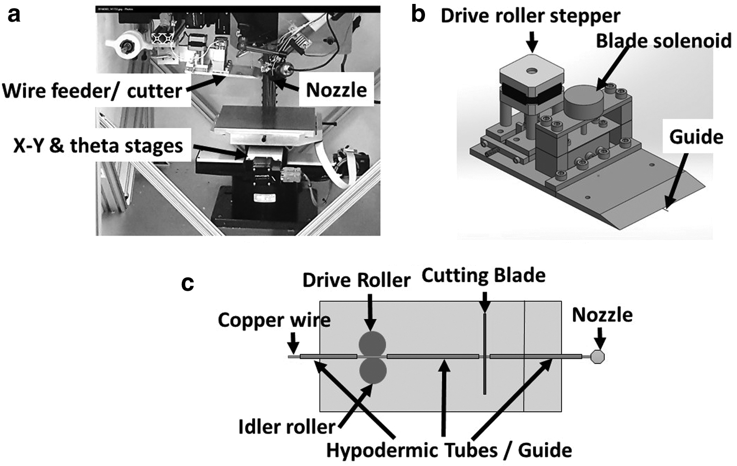
In FEAM, both the fiber (e.g., copper wire) and the matrix (e.g., a thermoplastic polymer such as acrylonitrile butadiene styrene (ABS)) are deposited using a single print head. The FEAM printer, as shown in Figure 1a, has a print head comprising of an extruder with a nozzle similar to those used in other material extrusion 3D printing processes and a guide located to the side of the nozzle orifice to deliver fibers. The exit of the guide is located in close proximity to the nozzle's orifice. As the print head moves, the proximity allows fibers to be introduced into a polymer, while it is being extruded. To successfully print fibers, the fiber must always be within the extrudate and be reasonably centered. To keep the wire centered on curved toolpaths a rotational or “theta stage” is used in conjunction with the traditional X-Y stages. All axes are controlled using DMC4183 and DMC2143 motion controllers (Galil Motion Control, Rocklin, CA). Basic operation and capabilities of this process have been described previously. 17
Wire feeding
Feeding fiber reliably from the spool to the print surface is a key task to making the FEAM process work. Although fiber feeding in the FEAM process can work on a number of different fiber types, we have demonstrated the process primarily using 127 μm diameter bare copper wire. Copper wire was chosen as the fiber of choice for its material properties, including high electrical conductivity, ductility, and it is relative low cost. The wire traveled through a guide that consisted of three metal hypodermic tubes with an inner diameter of 203 μm and an outer diameter of 407 μm. These hypodermic tubes were glued to the base of a wire feeder/cutter machined out of aluminum as seen in Figure 1b and c.
Wire was fed into the first hypodermic tube from a spool. Feeding was accomplished using two metal rollers. The drive roller was directly driven by a stepper motor synchronized to the planar motion with the DMC4183 motion controller. The idler roller was spring-loaded with adjustable tension to control the force of the idler roller on the wire and prevent extremes of wire slippage and deformation.
After the wire exited the rollers, it entered a second hypodermic tube and then a third. Between the last two hypodermic tubes there was a very small gap used for fiber cutting, as seen in Figure 1c. The wire exited the third hypodermic tube in very close proximity to the nozzle orifice. Due to the small inner diameter of the hypodermic tubes, a cut wire segment is able to push the segment in front until it finally exits the final hypodermic tube. To position the last hypodermic tube as close to the orifice as possible, the wire/feeder base had a sharp angle at its end as seen in Figure 1b. To enhance printing speed, a Luer taper syringe tip was used to deliver compressed air for solidifying the thermoplastics quickly after extrusion. 16
Wire cutting
The gap between the last two hypodermic tubes was set to accommodate a razor blade to cut the wire. The razor blade was actuated by a solenoid. Testing of different cutting blades was performed and it was determined that a Feather® (Feather Safety Razor Co., LTD., Osaka, Japan) double edge hi-stainless blades provided the cleanest cut. A clean cut was essential to ensure that the wire did not jam when feeding resumed. If the blade was dull or the force used to make the cut was not enough, a burr could be left in the wire which could inhibit wire feeding. The region of the blade contacting the wire began to wear after ∼30 cuts. Future versions of the feeder/cutter will automatically provide for a new section of blade to be used to cut the fiber to avoid excessive wear on the blade.
Wire junctions
Wire junctions were created by using an Electrically Conductive Polymer Composite (ECPC) 18 consisting of Kraton D1161P 19 (Kraton Performance Polymers, Inc., Houston, TX) thermoplastic elastomer mixed with silver-coated nickel particles. Both intralayer and interlayer junctions were demonstrated as seen in Figure 2c. Interlayer junctions were formed by laying wire segments on top of one another on different print layers. A cavity was left surrounding the wires, where the ECPC was deposited. Intralayer junctions were formed by laying wire segments side by side on the same print layer with a cavity surrounding them for the deposition of ECPC. ECPC was extruded from a separate, custom-made heated miniature screw extruder that was previously described. 1 The ECPC filled the cavity creating an electrical junction between the wires. The best measured junctions had resistances of 110 and 250 mΩ for interlayer and intralayer junctions, respectively. 18

Results
Using the FEAM system we were able to demonstrate the codeposition of copper wire with several different thermoplastics. Any arbitrary planar shape can be produced within the resolution of the extrudate width (∼0.45 mm). The fiber will remain encapsulated with a shape that directly depends on the preprogrammed stage trajectories and the solidification of the extrudate. Between successive layers at least one fiber can be continuous allowing for vertical circuitry to be produced. When more than one interlayer fiber trace is required for the desired part, in general, an interlayer junction must be used.
Figure 2a shows a stacked pancake coil of height ∼21 mm and outside diameter of ∼20 mm that was created by printing wire continuously in a spiral pattern, inward to outward and outward to inward on alternating layers. The resulting coil had 811 total turns and produced a force of 32 gf on a steel plunger when energized with 0.5 A of current. Figure 2b shows fed and cut segments of 127 μm diameter and 6 mm length copper wire encapsulated in BendLay, a semitransparent ABS-based thermoplastic (Orbi-Tech GmbH, Leichlingen, Germany). 20 The smallest wire segment length tested and printed reliably was 6 mm. The smaller fiber segments are pushed by the feeder into the extrudate flow using subsequent segments as a ram. The smallest bend we have been able to achieve with 127 μm diameter bare copper wire has a radius of 100 μm through a right-angle turn. However, the smallest continuous turn produced so far is a 3 mm diameter continuous helical coil. Wire segments can be produced with or without BendLay encapsulation. Wire segments without encapsulation were used where wire junctions were desired. Figure 2d shows a stretchable wire interconnect that was created by codepositing wire in a serpentine pattern. The device was elongated 5 cm without any observable change in resistance. Figure 2e shows a simple flashlight that was printed with wire for electrical connections and a soft thermoplastic elastomer “circuit board.” The flashlight consisted of a coin cell battery, surface mount resistor, an light-emitting diode, and copper wires. To connect and support the flashlight components, cavities were formed that had copper wire protruding within them. When an electrical component was inserted into the cavity, the wire bent downward to create an electrical connection with the component. A schematic representation of how the surface mount resistor was connected to the wires is shown in Figure 2f.
Conclusion
We are developing FEAM, an innovative multimaterial AM process. FEAM can be used with a variety of materials. Our current focus is using thermoplastic polymers as the matrix material and metal wires as the encapsulated fiber, with the goal of enabling the direct fabrication of circuit boards and active electromechanical devices. While there is still work needed to optimize the process, we have nevertheless addressed the three main challenges of FEAM, including achieving good centering of the wire within the extruded polymer; having the ability to controllably start and stop the wire to produce short wire segments; and demonstration of intralayer and interlayer junctions between wires. We have created a number of simple devices ranging from multilayer stacked pancake coils, a stretchable wire interconnect, and a printed flash light circuit.
Footnotes
Acknowledgments
This article is based on work supported by the National Science Foundation under Grant No. 1317961. Research was performed at the Laboratory for Additive Manufacturing, Robotics, and Automation, Department of Mechanical Engineering, Southern Methodist University, Dallas, Texas. The authors appreciate for their assistance Collin Clay, Todd Danner, Matt Galla, Parker Holloway, Austin Flanagan, Abigail Pingel, Moriah Momsen, Ashley Parks, and Grant Ryden.
Author Disclosure Statement
No competing financial interests exist.