




Abstract
Abstract
Multilayered 3D printing is already allowing architects, designers, and engineers to experiment with new design processes and new ways of production. A new field of research focuses on bio-inspired material finding and computer-aided fabrication processes. This article explores performance-driven design possibilities through a study of marine animals, specifically cephalopods, and then proposes a novel computational and fabrication model. This computation model, which is named “Pigment Skin,” imitates the cephalopods pigment distribution system to fit complex “host surfaces.” The study is divided into two parts; the first part focused on analysing the biological principles of Cephalopods skin and translating them to a computational model. This article focuses on the second part, with the main question being how to apply computer-aided prototyping using the latest multimaterial 3D printing to fabricate complex surfaces with gradient transparency based on a computational bio-inspired model. The presented 3D printing methods, techniques, and material tests demonstrate the first successful physical model results of complex prototype surfaces with gradient transparency using single and multimaterial 3D printing.
Introduction
From biology to programming materials
T
Research context
At the same time, 3D printing is an emerging field where designers, architects, and engineers experiment with new design processes and new ways of production based on bio-inspired material composites.9–11 Examples from the MIT Mediated Matter group12,13 as well as the 3D printed experiments by Zaha Hadid architects at the ACADIA 2014 conference 14 among others, demonstrate projects with multilayered materials, which were digitally designed and fabricated (Fig. 1). What is particularly interesting is that material-finding research projects focus on computational modeling and 3D printing, while drawing inspiration from biological organisms 15 (Fig. 2). This article proposes a research approach relative to programmable material systems that refers to current research on bio-inspired materials.
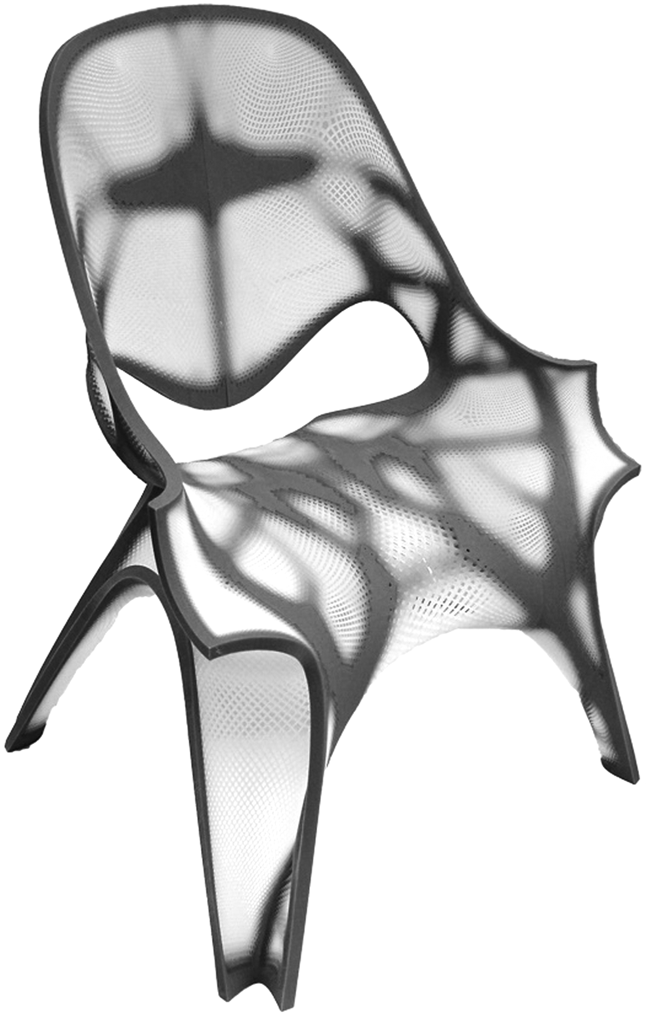
3D printed chair showcased at the ACADIA 2014 conference. Courtesy of Zaha Hadid Architects.

Metamesh: A hierarchical computational model for design and fabrication of biomimetic armored surfaces.
The current project focuses on a perfomative characteristic of biological organisms that has not been explored in architecture, of gradient transparency with the use of colored pigments. What is particularly interesting is the way gradient transparency can affect the design process through computation, a field that deserves further investigation.
This article is part of a PhD research in computational design and CAM for small-scale architectural installations. As mentioned above, the project was split in two phases; the first phase drew inspiration from marine animals and used computation to apply the design rules that define the functional frame of melanophore cells,16,17 from local scales (within a single cell) to global scales (the emerging patterns and zones within the whole body of a marine animal). These rules were then incorporated in a computation model, where pigments can be applied to complex surfaces. As an applied example, “Pigment Skin” was introduced, a synthetic computation system, where one can tune the performance of pigments, through aggregation, density, scale, and pattern. The findings of the first phase were presented at the 2015 eCAADe conference in Vienna (Fig. 3).
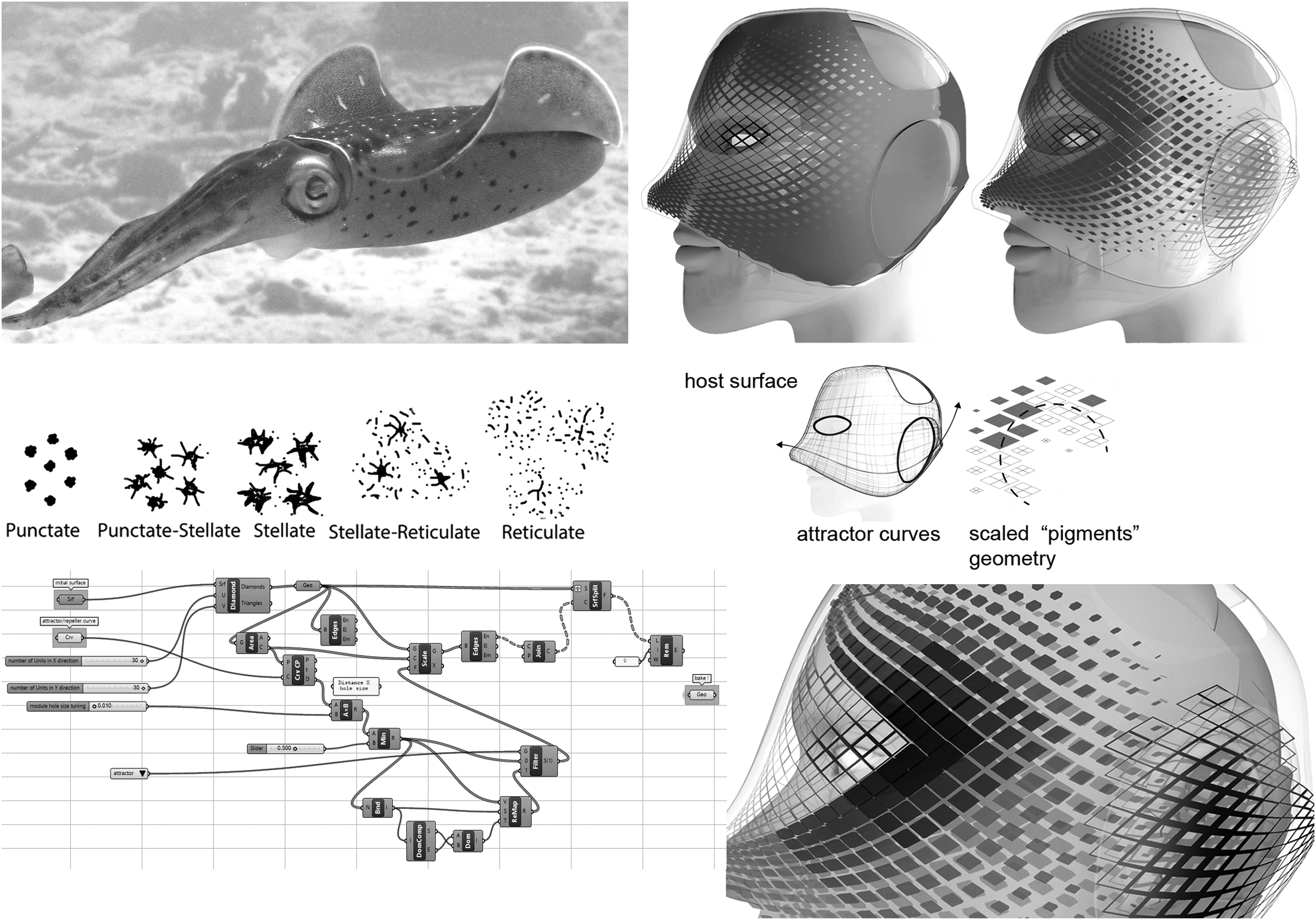
The first phase of this research project and the computation model for Gradient Transparency.
The second phase, which is presented in this article, focused on testing the fundamental exchange between the mathematical realm—in the form of digital modeling of gradient transparency (multilayered) surfaces—and the material realm—in the form of material prototype fabrication and manufacturing. The main question was whether computer-aided prototyping and more specifically 3D printing can be used for the fabrication of proof-of-concept physical models of the Pigment Skin computational model. The current phase focused on experimenting with single and multimaterial 3Dprinting methods to test the ways to produce and eventually compare, proof-of-concept physical models and their ability to have the gradient transparency effect.
To provide a coherent and understandable output, this article provides a brief synopsis of the first part and focuses on the second part of prototype fabrication using 3D printing of a novel, composite architectural material.
Printing complex surfaces with gradient transparency
While plastic is the most common material used in a vast spectrum of products, from kitchenware to furniture and architectural construction, 18 there was no technology to accurately control in micro scale its transparency through its composition, before multimaterial 3D printing. There are currently no research projects investigating transparency control through computational and 3D printing methods.
Contrary to manipulating plastic using existing fabrication methods such as injection molding, or basic 3D printing using PLA or ABS plastic, 19 advanced multimaterial 3D printing technologies allow us to design specific patterns and composite materials with different percentages of material mixtures, thus enabling us to precisely control the transparency or even flexibility or a 3D printed material. The materials used for this multilayer fabrication tests are acrylic plastic polymers cured with UV light, 20 and are explained further in the next chapter. Three-dimensional printing can be used as a new method for producing complex bespoke plastic surfaces with 3D preprogrammed shapes and composites that can achieve any required transparency through the use of populated, multiple geometries with different sizes, the same way cephalopods use melanophore pigments. The presented methods offer alternatives to overcome the existing limitations in utilizing plastic for design and manufacturing. By taking advantage of the latest 3D printing technologies, material can be deposited in precisely defined patterns. Utilizing such capabilities, custom pigments can be 3D printed, which can have any geometry (circles, diamonds, squares, etc.) specifically to enhance opacity or transparency, through the geometries sizes and distances while minimizing production labor (Fig. 4).

3D printed test model using diamond geometries with different transparencies and sizes.
Materials and Methods
The computational model was created after the microscopic examination of melanophore cells of cephalopods. 21 The microscopic examination and analysis of the morphological and emerging patterns led to the biological epidermis design rules for three levels of resolution: local, regional, and global. These design rules were then incorporated in a computational model, which can be applied to any NURBS surface with complex geometry, to create the gradient transparency effect through multiple pigment geometries. It is important to note that the custom pigments of the computational model can have any geometry (circles, diamonds, squares, etc.) specifically to create gradient opacity or transparency on a complex surface, through the geometries sizes and distance between each other. The biological epidermis design rules were applied to the computational model using the Rhinoceros and Grasshopper software.
This was achieved through the use of parametric component population (PCP) to populate the pigments on the host surface. PCP has become a common method to adapt discreet geometrical components to complex surfaces and shapes. 22 The host surface is modeled as a NURBS surface subdivided into U and V directions, on which the geometric components (here the pigments) are populated and manipulated through main attractor curves. As stated above, this article explores the materials and methods to fabricate materialized versions of the Pigment Skin computational model. Multimaterial 3D printing was chosen as a way to materialize the project. One of the key choices made, which refers to the main research question of how to materialize the bio-inspired computational model, was using different and computationally controlled mixtures of 3D printing materials, to create the gradient transparency effect.
Method + materials A: transparency through pigment (geometry) density—single material
This method uses only pigment density to create less or more transparency. The eye and ear areas are treated in analogy with the biological Punctate melanophore clusters (area with high pigment density) and the Reticulate (Branching) melanophore clusters23,24 that are already studied in the first phase of this project. The parametric model allows using the eye and ear curves either as attractors and repellers, creating inverted geometry conditions. This method can create complex outcomes, when the eye curve is parametrically used as a repeller and the ear curve as an attractor (Fig. 5). Applying the diamond pigments on the host surface and scaling them according to their distance to the attractor curves creates the gradient transparency effect.
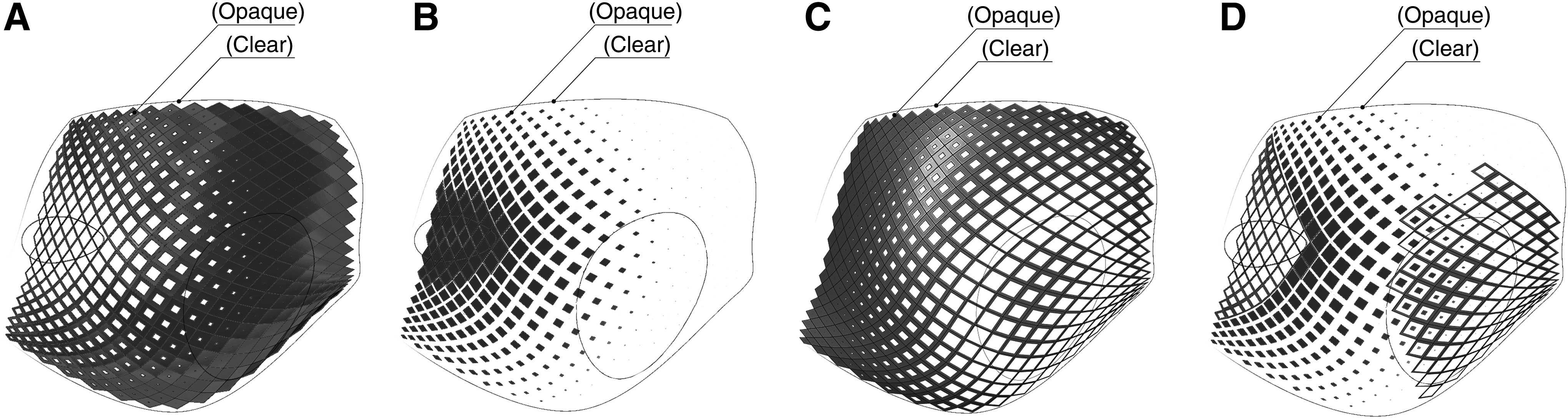
Manipulating the parametric model allows for different transparencies as well as different sizes of pigments on the grid, which are also controlled through the computational model (Fig. 6). For this method, The Frosted Ultra Detail plastic material (an acrylic plastic polymer) from Shapeways 25 was used both for the pigment geometries and the host surface. It was chosen due to its inherent transparency quality, as well as because it is already commercially used by companies that can 3D print bespoke models, making it accessible to researchers (Fig. 7). The material is cured by UV light with 29 μm layers that are 3D printed with an accuracy of ±0.1 to 0.2 mm for every 100 mm. They are heatproof to 80°C.
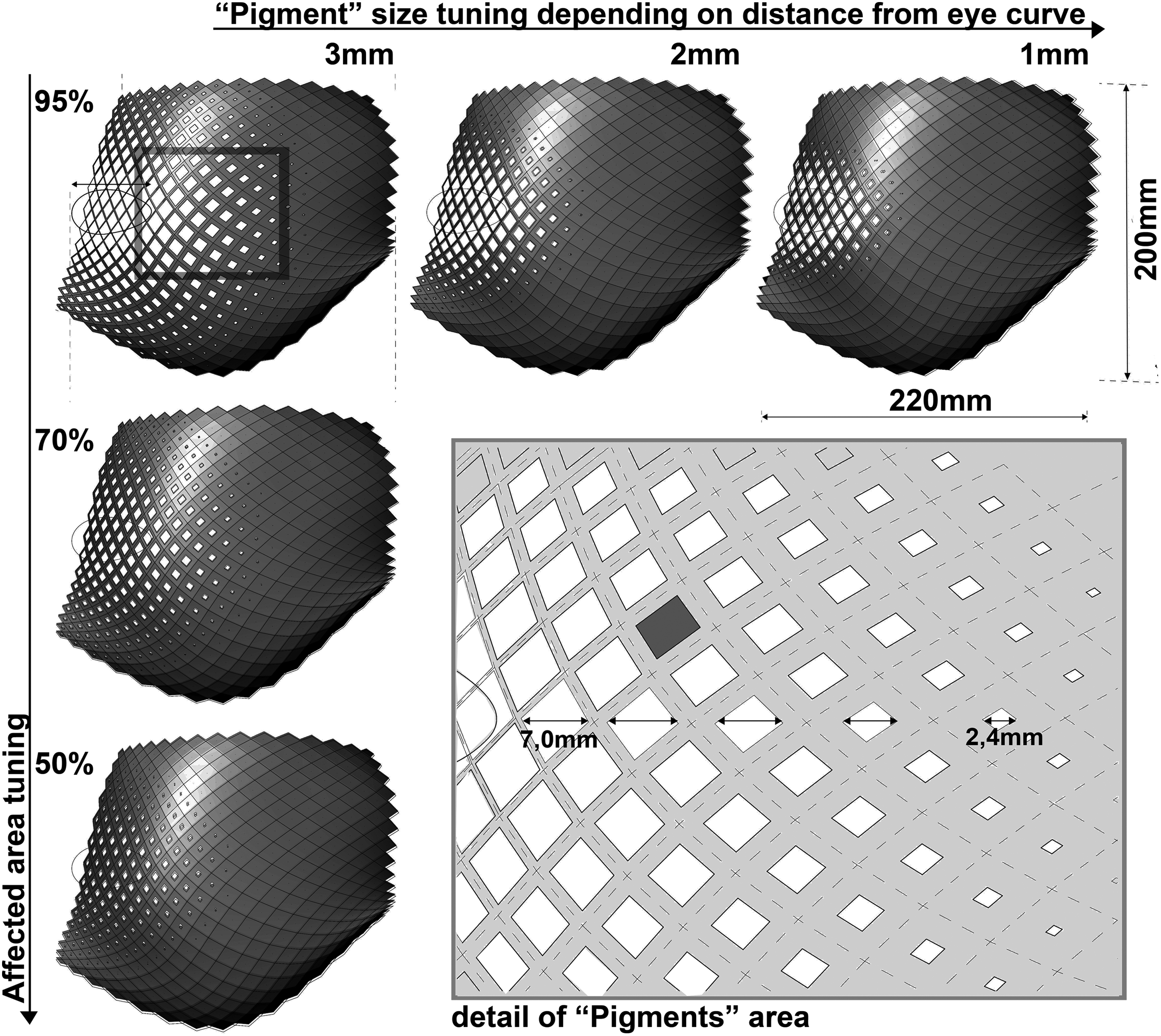
Tuning the size and density of the Pigment geometry in the computational model.
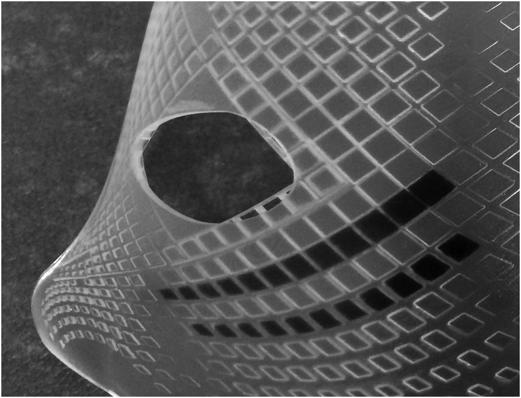
Frosted Ultra Detail material 3D print.
Method + materials B: transparency through pigment (geometry) density + pigment transparency
Compared with the previous method, this approach becomes even more elaborate, since one can also control the pigment transparency. The parametric model uses a Grasshopper software definition, which allows for controlling the transparency of the pigments' geometry, depending on the distance from the attractor or repeller curve (Fig. 8).

Color coding showing the Pigments' transparency based on their distance from the eye area. Color images available online at www.liebertpub.com/3dp
The 3D Systems ProJet 5000 3D Printer was chosen due to its ability to mix and create materials with different transparency on the fly (while 3D printing), which allowed for the desired gradient transparency effect (Fig. 9). The clear amber VisiJet M5 MX was used for the host surface and a differentiated mix of Visijet M5-X and Visijet MX 26 was used for the pigment diamond geometries.
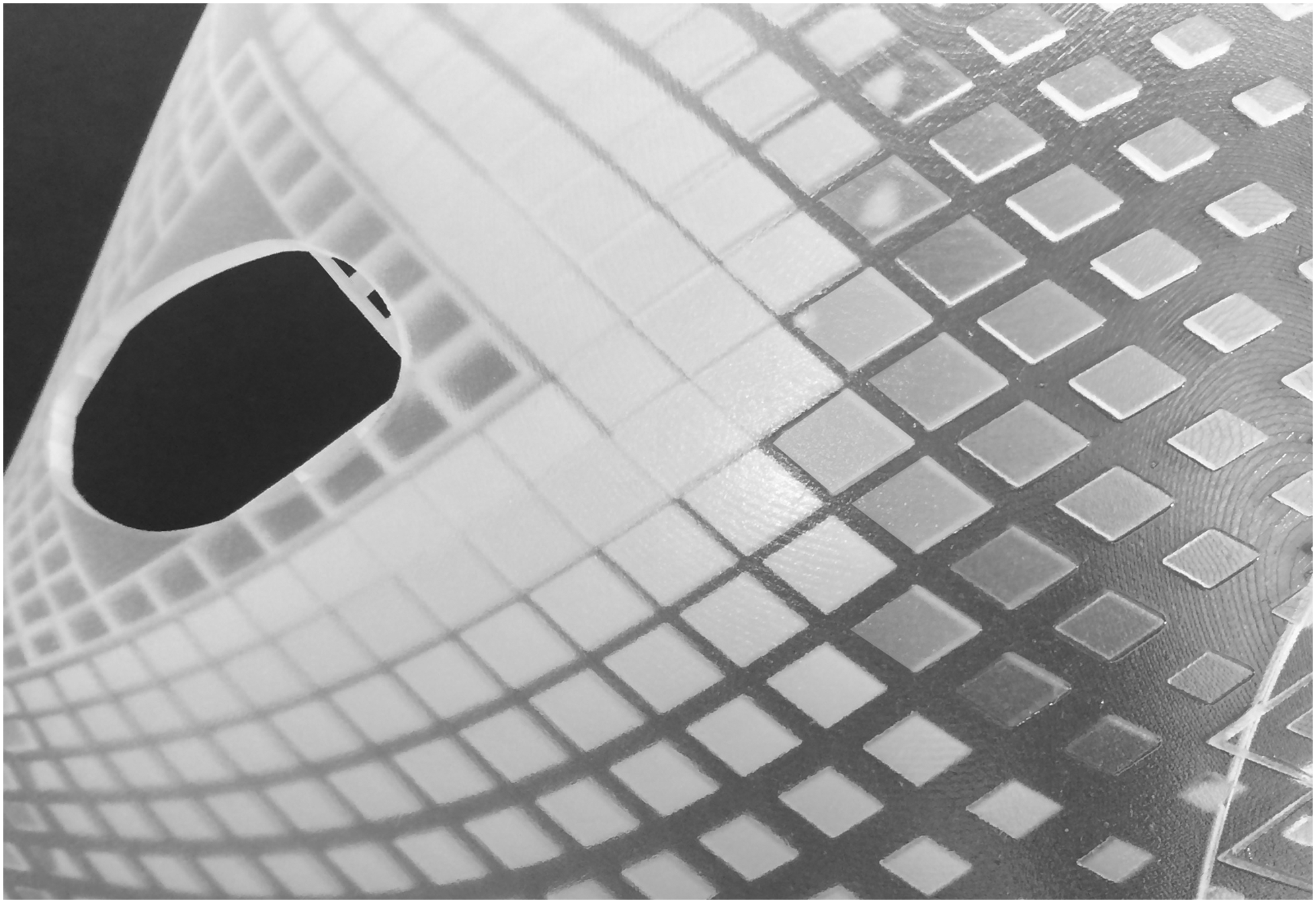
Multiple materials with gradient transparency 3D print.
The ProJet 5000 and VisiJet hybrid materials were also chosen due their ability to match the high quality of injection molding plastics, as a response to the existing high-quality plastic fabrication methods. Another important factor for this choice is that they are not currently commercially used by companies that can 3D print bespoke models for anyone. Probably, this is the next step that will be commercially presented to both researchers and the general public within the next coming years, so this project is hopefully representing a digital design/fabrication approach that could be widely adopted in the future.
VisiJet M5-X is a strong, rigid material with a hybrid ABS/polypropylene-like performance-and-feel that makes brilliant white parts. This material makes bright white parts that look like they have been injection molded. Parts made from this material are rigid, making it an excellent fit for packaging products, including bottles, household plastics, piping, valves, and other parts that call for stiffness.
These polymers are also cured by UV light throughout the 3D printing process with an accuracy of (0.025–0.05 mm) per inch of part dimension. The heat distortion temperature is 65°C for VisiJet M5-X and 39°C for VisiJet M5 MX.
Preparing the digital files for fabrication for method B
Magics 15 software was used to clean up the part files (it was also used to turn shell geometries to parts), so only the minor repairs were necessary, some inverted normals, overlapping triangles, bad edges, etc., the usual glitches, which are found in most .stl files that are commonly used for 3D printing.
The Geomagic Print software was also used, a printer client manager from 3D Systems, during which one has to import one shell, then one more, delete the first, reimport the first and then import the rest so that they would correctly relate to each other in 3D space and be 3D printable as a single entity (Fig. 10).

Importing the geometry in the “Geomagic print” software.
This step was crucial to follow; otherwise, the printer laid out all the shells on the platen as separate entities without any way to create an assembly. Once correctly assembled, a group from the shells was created so that they can be moved en bloc to optimize the build orientation. Finally, material properties were assigned (percentage of each different material) to each shell to obtain the required graduation from white to clear material.
This simple process took a lot of experimentation to arrive at, but it was used since with similar results, therefore, it appears to be a robust method of working with multiple shells that were correctly spatially related to each other before the file repair process. If no initial assembly has been done, there is no manual method available to accurately create that assembly later other than visually and when looking at a 3D object on a 2D screen, which is all but impossible to judge.
Fabrication
As mentioned above, two methods of 3D printing were used, both of which are using the Multijet Modeling (MJM) process. During this process, molten plastic is deposited onto an aluminium build platform in layers using several nozzles, essentially like a large print that sweeps across the build layer. As the heated material jets onto the build plate, it solidifies instantly. Wax is used to create supports that brace the part during production. After each layer is deposited, it is cured, or polymerized, by a wide-area UV lamp. UV lamps cure each layer, and the build platform lowers for the next layer. This process continues layer by layer until the layers of thermoplastic build up into a model (Fig. 11).
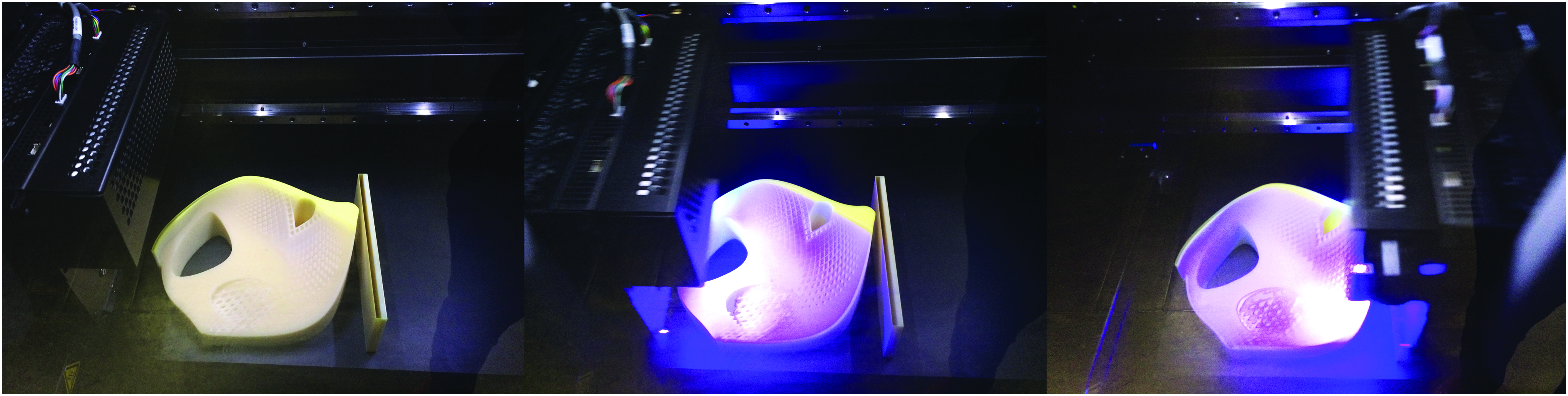
UV radiation curing during 3D printing. Color images available online at www.liebertpub.com/3dp
Postprocess
During postprocessing, the part was placed in a Genlab incubator at 60°C until the support material was mostly removed and then the part was immersed in a bath of EZ rinse C solution to remove the remainder. The part was not cleaned further to retain the oil-based finish and best clarity required.
Results
Gradient transparency through pigment (geometry) density—single material results
The parametric Grasshopper software model allows populating different geometries on the host surface using PCP mentioned above. In this specific study, diamond-shaped geometries were used, due to their reference to structure and possible future use in structural surfaces. As explained, to create gradient transparency based on pigment size, all geometries are locally scaled with the use of an attractor curve. Controlled transparency through differentiated surface printing has been achieved through the control of density and pattern of the 3D printed pigment surface.
As is can be seen, the denser the pigments geometry, the less transparent the host surface becomes. The host surface (the mask) is inscribed in a rectangle, which is 200 mm tall by 220 mm wide (Fig. 12).
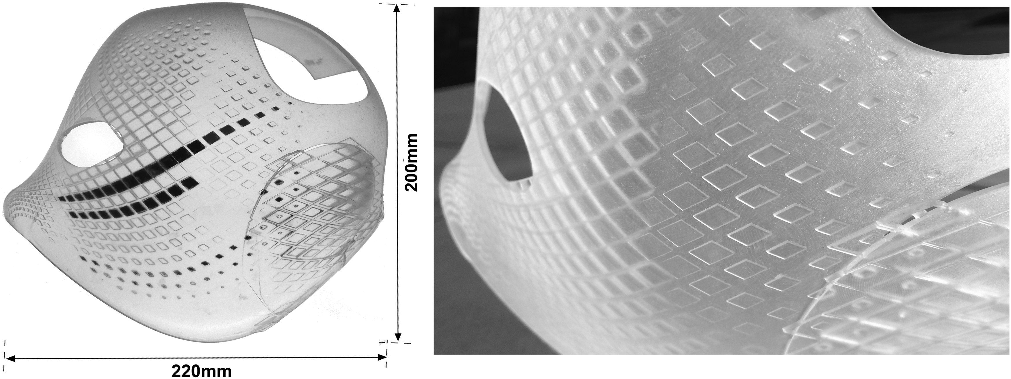
Final single-material 3D print (some of the pigments are color coded black to be clearly visible).
The host surface was successfully 3D printed without any faults with a minimum thickness of 2 mm set by the 3D printer limitations as well as the need for a robust host element. The pigments (some of which are color coded black in the images to become clearly visible), vary from a minimum of 0.8 × 0.8 × 2 mm (height) to a maximum of 7 × 7 × 2 mm (height) near the eye area (Fig. 13). The minimum distance between the pigments is 0.6 mm, which again occurs near the eye area, where we set the minimum possible transparency. The minimum size for the pigments' geometries is set by the 3D printer limitations for the Frosted Ultra Detail Plastic material by Shapeways, which is an acrylic plastic polymer.
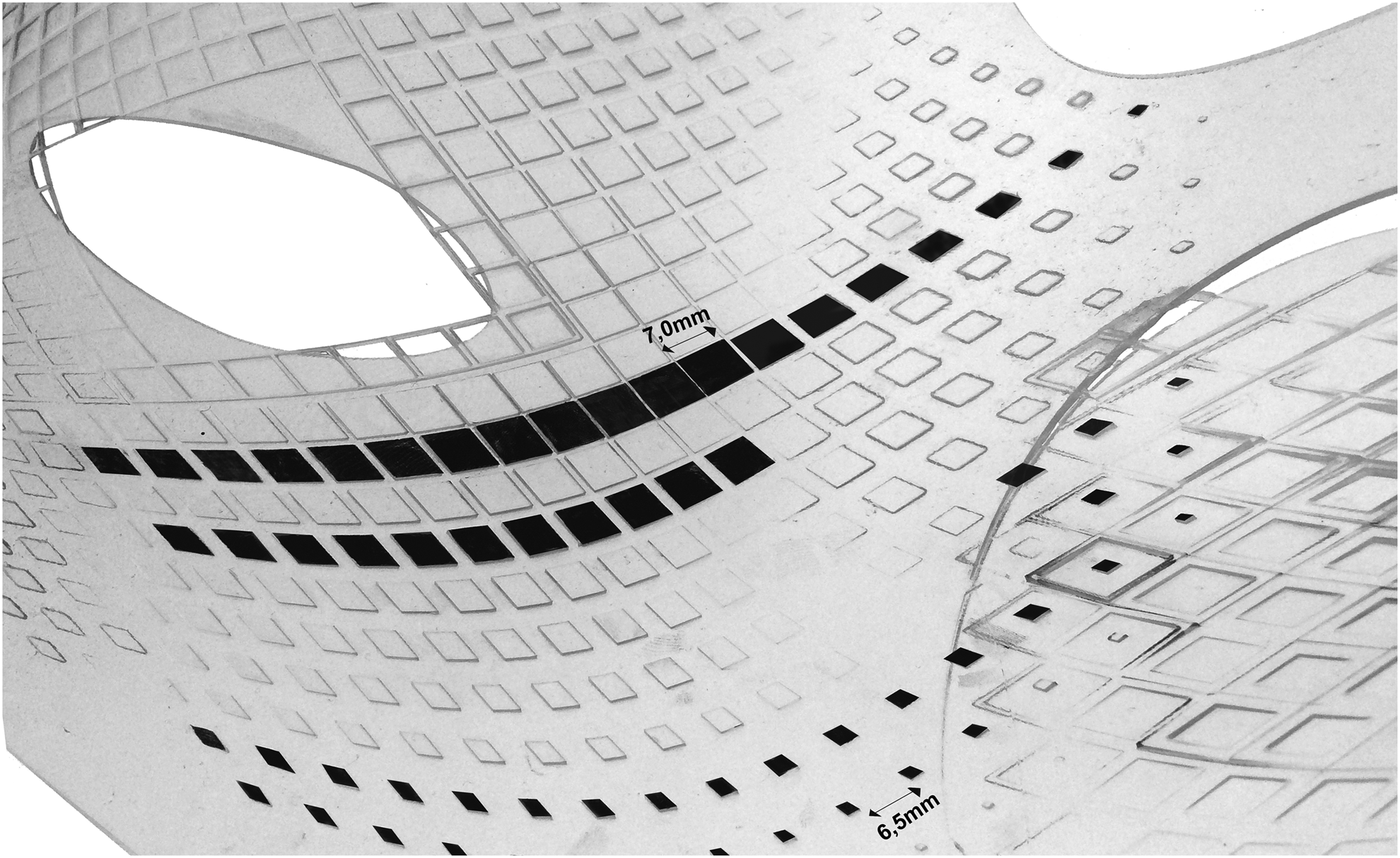
Detail of the single-material (acrylic plastic) 3D print (some of the pigments are color coded black to be clearly visible).
Gradient transparency through pigment (geometry) density and pigment transparency—multimaterial results
Using the ProJet 5000 3D printer by 3D Systems allowed 3D printing a prototype with pigment geometries with varying transparencies. The pigments were grouped in seven groups in the computational model, varying from 0% to 20% transparency. A sample with all seven different transparencies was also 3D printed to have an overview of this difference (Fig. 14).

Multimaterial 3D printed sample showing gradient transparency from 20% (left) to 0% (right end).
The computational model allowed for selecting any area on the host surface, which was needed to be more or less transparent. In this 3D printed prototype, the closer the pigments are to the eyes, the more opaque they are. This allowed for complete opacity in selected areas of the mask (the eyes) which fade to more transparent zones (the cheeks). The same logic was applied to the ears area pigments, which also fade to the more transparent cheeks zone (Figs. 15 and 16). Again, the host surface (the mask) was 3D printed with a minimum thickness of 2 mm. As mentioned above, the clear amber VisiJet M5-MX Hybrid Material from 3D Systems was used for the host surface and a differentiated mix of VisiJet M5-X and VisiJet MX was used for the pigment diamond geometries. Again, the host surface (the mask) is inscribed in a rectangle 200 mm high by 220 mm wide and was successfully 3D printed with a minimum thickness of 2 mm to ensure robustness. Like the single material prototype, the pigments vary from a minimum of 0.8 × 0.8 × 2 mm (height) to a maximum of 7 × 7 × 2 mm (height) near the eye area (Fig. 17).
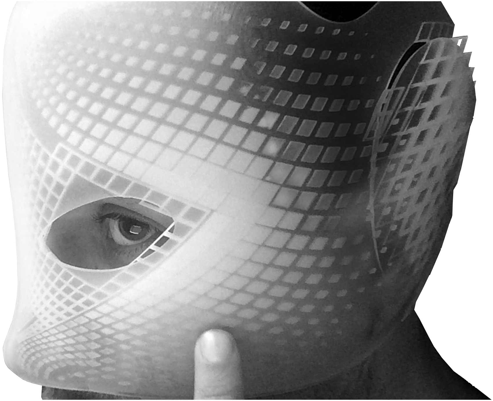
Multimaterial 3D printed prototype with gradient transparency pigments diamond geometries.
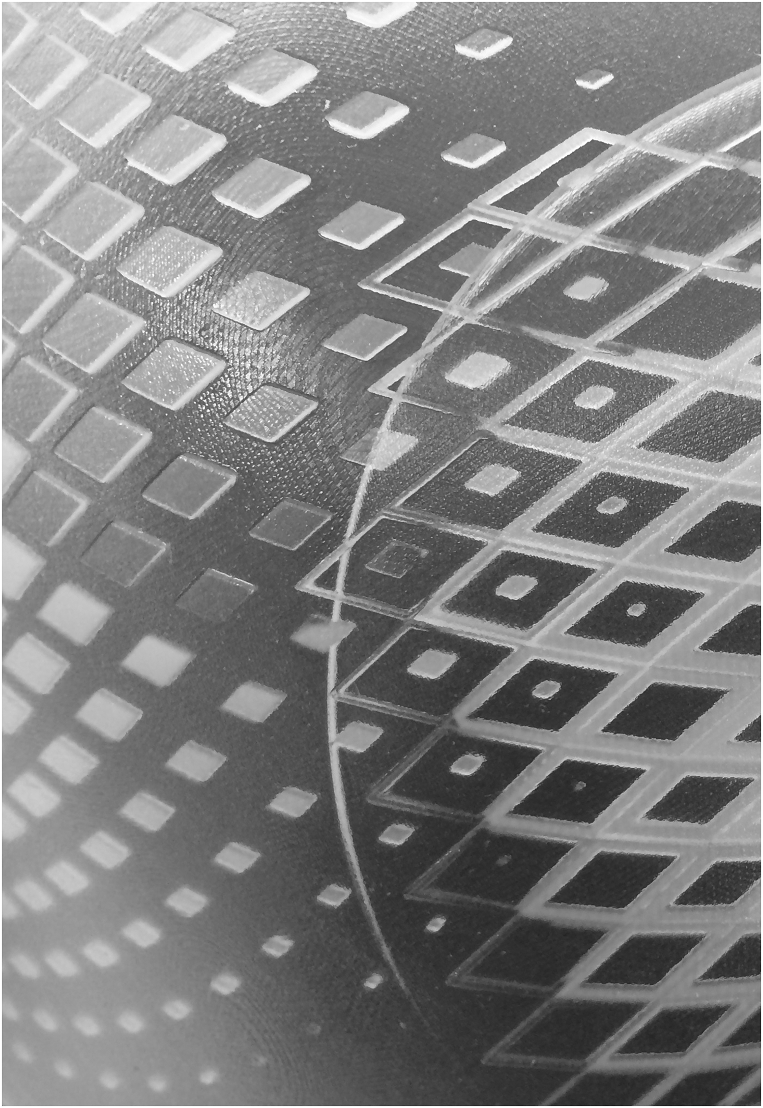
Multimaterial 3D printed prototype with gradient transparency (detail of the fading effect within the cheeks area).

Multimaterial 3D printed prototype with gradient transparency (detail of the fading effect within the eye area).
Discussion and Next Steps
Integration of transparency methods and PCP
This article outlines the processes and results, which were conducted in an effort use 3D printing as a way to fabricate complex surfaces with gradient transparency based on a computational biomimicry model.
For the computation design phase, PCP was used as a method to adapt discreet geometrical components to complex surfaces and shapes. The host surface was modeled as a NURBS surface subdivided into U and V directions, on which the geometric components (here the pigments) were populated and manipulated through main attractor curves.
By taking advantage of current 3D printing technologies, the material was deposited in precisely defined mixtures, controlling the material's transparency for groups of pigment geometries. Utilizing such capabilities allowed to design custom transparency on any desired area of the host surface. At the same time, just as cephalopod skin, specific patterns are created on a global scale on the host surface, which tend to attract the observer's attention to specific areas. Based on the research concluded to date, two key methods have been identified to augment and program gradient transparency.
Method A: Gradient transparency through pigment geometry density—single material
The computation model allows tuning the pigment densities in selected areas of the complex surface, creating gradient transparency as long as a semitransparent or clear material is used. In this case, the acrylic plastic polymer (Frosted Ultra Detail, as Shapeways names it) was used, which has a light amber hue and has a light frosted finish. To completely conceal areas and have 0% transparency, the prototype shows that a second material from a double material 3D printer would have to be used such as black PLA plastic for the pigments geometry (and transparent PLA plastic for the host surface).
Method B: Gradient transparency through pigment geometry density and pigment transparency—multiple materials
This method takes the above approach even further since the computation model allows tuning of the pigment transparency. This appears to be the optimal method to have further control over local transparencies. The global effect is the same for both methods (both host surface prototypes have the same pattern), yet the local effect varies due to the different materials and techniques that were used to 3D print the pigment geometries (Fig. 18).
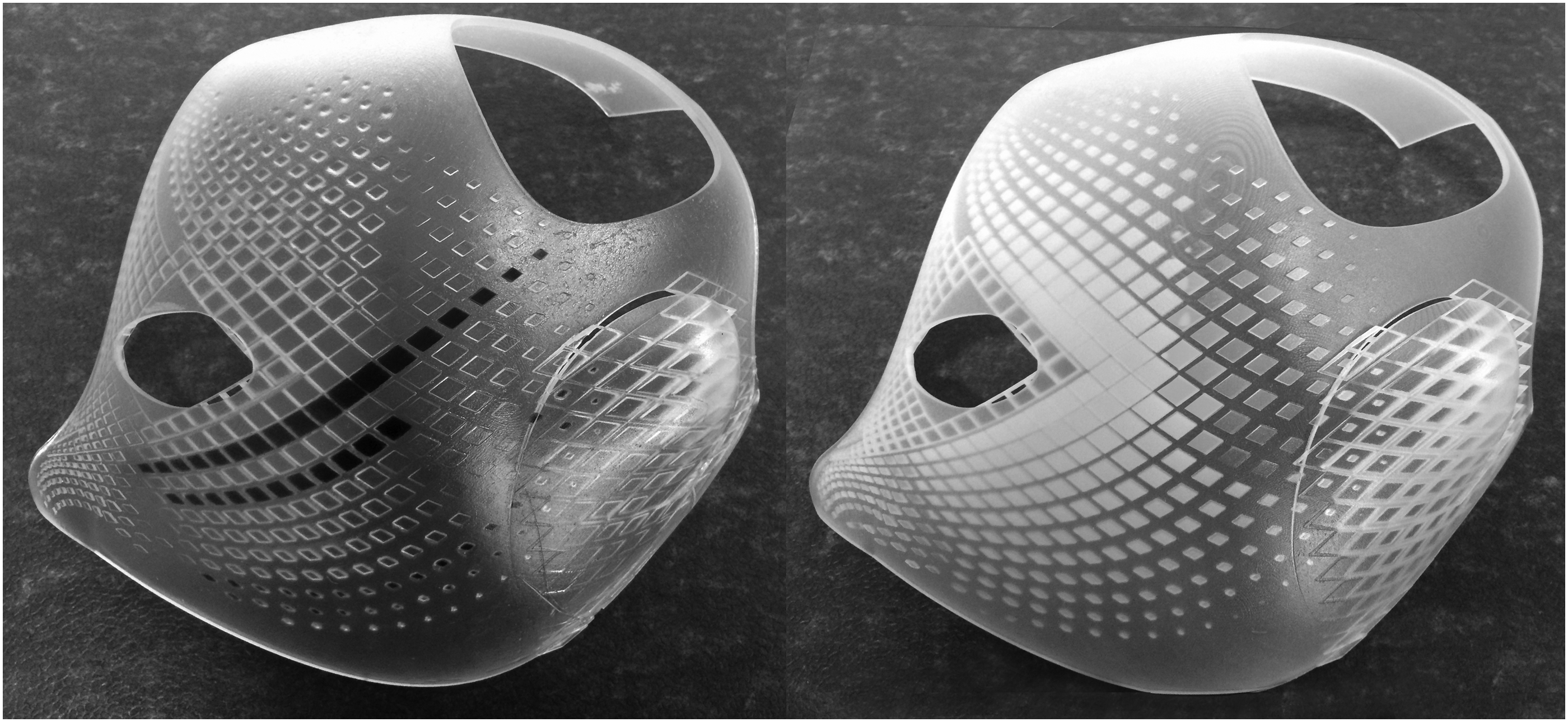
Single material 3D printed result (left) and multimaterial with gradient transparency pigments 3D printed result (right).
Further material and performance research
The results suggest that using the same pigments' geometry can lead to different ways to control transparency, using either single or multiple materials. Further research aims at testing different ways to control the pigment transparency in real time. One of the options would be to add microtubes, just like melanophore cells are connected in biological organisms23,24 within the computational model that interconnect the pigments geometries. In such a scenario, following Method A with a single material would allow us to have architectural surfaces that change from transparent to patterned surfaces with varying transparency using liquids like Ferofluid 27 and electromagnets.
Another approach that could be tested in the future would be adding a third layer of micro electrical wiring and pigment smart e-foils to control the pigment transparency in real time. The host surface would again be a single transparent material like clear PLA plastic (Fig. 19). This could mean that gradient transparency architectural surfaces could be 3D printed and used as screens with custom-made patterns both in interior and exterior spaces, in different scales, from partition walls to billboards. The proof-of-concept mask models that were 3D printed during the second phase of this project showcase how this approach can also be used for fabricating small-scale objects such as wearable garments.
Visualization showing potential real-time pigment control through micro wiring and smart e-foils.
E-textiles 28 or e-foils are textiles that enable digital components to be embedded in them. Studio Roosegaarde has experimented with wearable garments that embed e-foils that become increasingly transparent from black or white color. 29
Adjustments of material composition, number of printed layers, and thickness are some of the parameters that are currently under consideration for testing to achieve more precise and consistent results at multiple scales.
Digital tools
The presented projects highlight both the importance of grouped geometries generation and group geometries control to achieve the gradient transparency effect. However, limited tools are currently available to easily access and manage these variables within a design interface. Direct and real-time access to printing parameters and real-time machine control/feedback are critical for the effective optimization of the multilayer prototypes.
As mentioned, computation and fabrication models are critical to facilitate both the integration of 3D-printed methods into a greater research community and the integration of such methods in industry applications. Further development of computation and fabrication platforms can offer greater design capabilities for complex geometric manipulation with gradient transparency and better communication between design and 3D printing production.
Conclusion
This research contributes to the research area of programmed materials with the novel effect of gradient transparency, which can be applied to complex surfaces and can be easily produced and highly tuned through multimaterial 3D printing.
This project used biological organisms as a source of inspiration (in this case marine animals) and eventually proposed a controllable computational design model through microscopic examination of the biological design rules of the organism. PCP was applied with the use of the Grasshopper software and proved to be successful in controlling the biological epidermis pigment effects in a computational model. This fact shows that PCP could also be used in diverse future projects, where PCP is used to control the materiality of large numbers of components other than controlling the most common parameter of geometry.
At the same time, this article contributes to the research field of material finding and fabrication through the use of multimaterial 3D printing for the production of novel materials with gradient transparency. It proposes a new fabrication method of 3D printing materials that can embed differentiated and tuned transparencies within their body, a technique that has not been addressed until today. Test models were produced through multimaterial 3D printing of seven different mixtures within the same final material body. This was the main way to enhance the gradient transparency effect, while opening up new possibilities for tuning multi material, 3D printed semitransparent architectural materials.
One of the possibilities outlined are the smallest possible pigments and host surface geometries, using the latest 3D printing processes. Applying pigments that come down to the smallest possible 3D printable dimensions allowed creating 3D printed prototypes that showcase the current fabrication possibilities when it comes to the minimum scale of artefacts. Apparently, these methods could be applied to fabricating larger scale objects, which would also mean breaking down the digital model in 3D printable elements or panels that can be used in a number of applications from architectural building surfaces, to billboards and wearable garments.
This article contributes to the research field by presenting the series of design and production methods that were developed that utilize multimaterial plastic 3D printing techniques for programmable material products. Single and differentiated multimaterial 3D printing was outlined as the main method for 3D-printing complex surfaces with gradient transparency.
Both Method A and Method B use the same base pattern, but have a different gradient transparency effect. Method A could also potentially be used as a base for more complicated prototypes that embed further layers for real-time control of the pigments transparency. Method B could be seen as a method for designing and manufacturing a final product with a specific (unchangeable in real time) gradient transparency effect.
The presented methods propose a new approach to programming materials with controlled gradient transparency through 3D printing. These methods can lead to precise and controllable results with no human labor, which cannot be achieved with the current physical forming/molding processes. Moreover, such methods provide the capacity to enhance design agency by having complete control over transparency, material composition, and full customization of the design and fabrication processes.
Footnotes
Acknowledgments
The PhD research project was funded by the “YKI Fellowships of Excellence for Postgraduate studies in Greece–Siemens Program.” Special thanks to Chris Charlesworth for his crucial help in preparing the files for 3D printing.
Author Disclosure Statement
No competing financial interests exist.