
Abstract
Abstract
This article introduces a custom-built multimaterial 3D printer that is capable of depositing three different materials during one print. The printer utilizes both continuous and droplet direct-write methods. The printer itself is fully controlled via LabVIEW, allowing all aspects of the printing process to be adjusted, and the geometry for the printer is processed via a point-cloud method. This represents the first multimaterial printer to fabricate a composite object made from metal, rubber, and plastic all within one print. There is a good resemblance between the original design and the final printed component, further advancing the capability for multimaterial printing.

Introduction
A
It has been shown that continuous and droplet direct-write techniques2,3 can be used to deposit a variety of materials, including ceramics, resins, and polymers.2,4–6 Recent research has shown that various types of elastomers can also be printed with these direct-write methods,7–9 as well as low melting point alloys.10,11 Because of their “direct-write” nature, with different materials in separate reservoirs, they are also well positioned for multimaterial printing because of their low risk of material cross contamination when compared to alternative printing methods such as stereolithography or selective laser melting. 1
In this article, we introduce a custom-built 3D printer that utilizes these recent advances in direct-write printing to fabricate parts with up to three different materials. The use of both inkjet and continuous direct-write nozzles allows material deposition of UV cure resins, elastomers, and low melting point alloys. The printer is fully controlled by a custom program designed in LabVIEW, and can process stereolithography file format (STL) files, which facilitates the wider use of the printer. To demonstrate the capability of the custom-made printer, a three material composite object, known as a locally resonant metamaterial (LRM), 12 is designed and then fabricated by the printer. The LRM contains solder alloy, latex rubber, and a UV cure resin.
Printer Setup
Printer hardware
The printer was designed to deposit a range of different types of materials. Of the various printing capabilities, direct-write methods have proven some of the most adept for multimaterial printing,1,13 largely due to their lower risk of material cross contamination and large range of printable materials. As such, there are three different nozzles on the printer; two inkjet devices and one continuous direct-write system (Fig. 1).
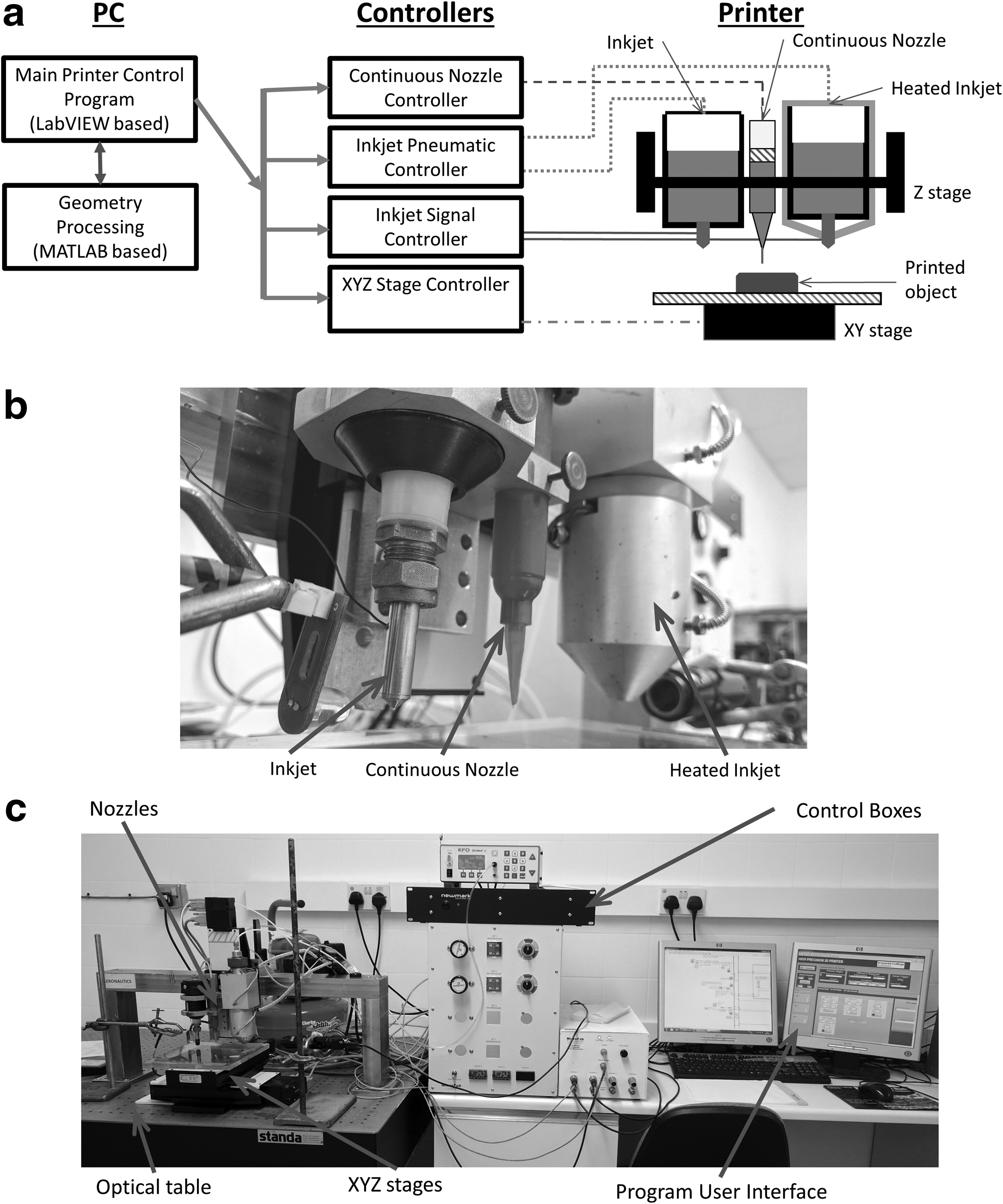
The inkjet nozzles were purchased from MicroFab and are of a piezoelectric design. Each has an orifice diameter of 80 μm. The recommended maximum viscosity of the material being deposited is 20 mPa. To increase the potential range of materials that can be printed, one of these nozzles is part of a Polymer Jet™ system, which allows the printing material to be heated up to 240°C. This reduces the viscosity of a material to bring it into the acceptable range for inkjet printing. The second inkjet nozzle does not heat up and deposits material at room temperature. The nozzles are connected to a signal generator, which can send different signals to each device, allowing one material to be printed at a time or both simultaneously. The signal required to make a droplet is material dependent and is triggered by the control program. In addition, the nozzles are connected to a compressed air supply and a vacuum supply to ensure the correct pressure for printing.
The continuous direct-write nozzle is part of the EFD Nordson Ultimus™ V system. A compressed air supply is connected to the Ultimus V control box, which feeds controlled air pressure to a 10 cc syringe containing the material to print. The material is extruded through the nozzle at the end of the syringe by a plastic plunger. The Ultimus V system applies a small vacuum after each deposition to ensure correct deposition amounts if the material to be printed has a low viscosity. This combination of nozzles gives the printer a greater choice of materials to deposit in one object than currently offered by other multimaterial printers. 1
The movement of the nozzles is carried out using Newmark Systems XYZ linear stages. The three stages can be operated independently and have a quoted accuracy of 3 μm and a repeatability of 0.5 μm. The three nozzles are attached to a vertical stage that moves in the Z direction. The substrate is attached to the X and Y stages. As such, the item being built moves under the appropriate nozzle, and as the material layers “build up,” the height of the nozzles is increased relative to the printing bed. The acceleration, deceleration, and velocity of the stages are controlled by the user and are set before printing. Glass microscope slides are attached to the unheated print bed and the printer deposits onto these glass substrates. The printer is set on an optical table to reduce unwanted vibrations during the print. A silent air compressor provides the pneumatic pressure that needs to be applied to the three different nozzles.
LabVIEW control program
A LabVIEW program was created to control the 3D printer and allows for full control of the printing process. The program was created such that each function is in a different state, which is called upon as needed. This allows additional parts to be added to the program without affecting the functionality of the original program. Currently, there are six different states in total, as seen in Figure 2.
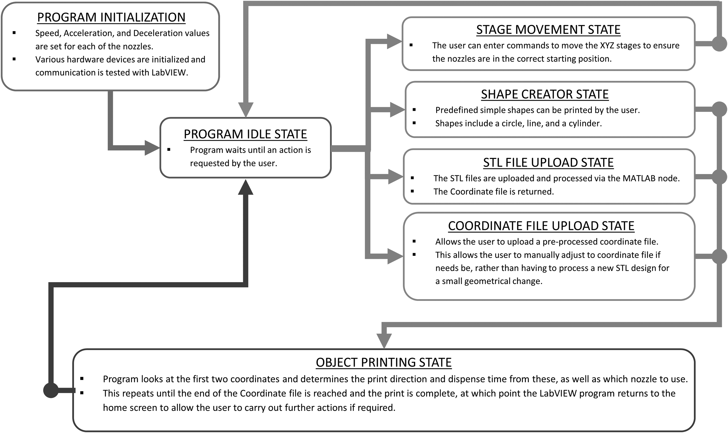
Overview of the LabVIEW control program. The program can be customized to add more functionality as required.
The user specifies the printing parameters, including the speed of the XYZ stages, the nozzle print signals, and nozzle pressures, before initiating the program. There are several predefined functions built into the program, such as the ability to make a single line, a circle, or to build a cylinder. These were created to allow the user to experiment with a new material to see how it deposits (i.e., does the material spread, is the nozzle prone to clogging) and find the optimal settings such as nozzle speed, droplet frequency, and pneumatic pressure.
The main function of the printer is to print the multimaterial parts based on CAD-generated STL files. For this purpose, the user uploads the STL files into the program, one for each nozzle that will be used. LabVIEW sends these files to MATLAB which then processes the STL files and creates a shell file (see the Geometry processing section), which is then read by LabVIEW. Based on the shell file, LabVIEW coordinates the sending of commands to the various nozzle and XYZ stage hardware control boxes to print the part(s) (Fig. 2). If a part's geometry has already been processed by the MATLAB program, the shell file can be uploaded directly into the control program from an external source and the print can proceed as normal. The print can be paused if a nozzle's reservoir needs to be refilled or for inspecting the partially built object for quality and defects before proceeding.
Geometry processing
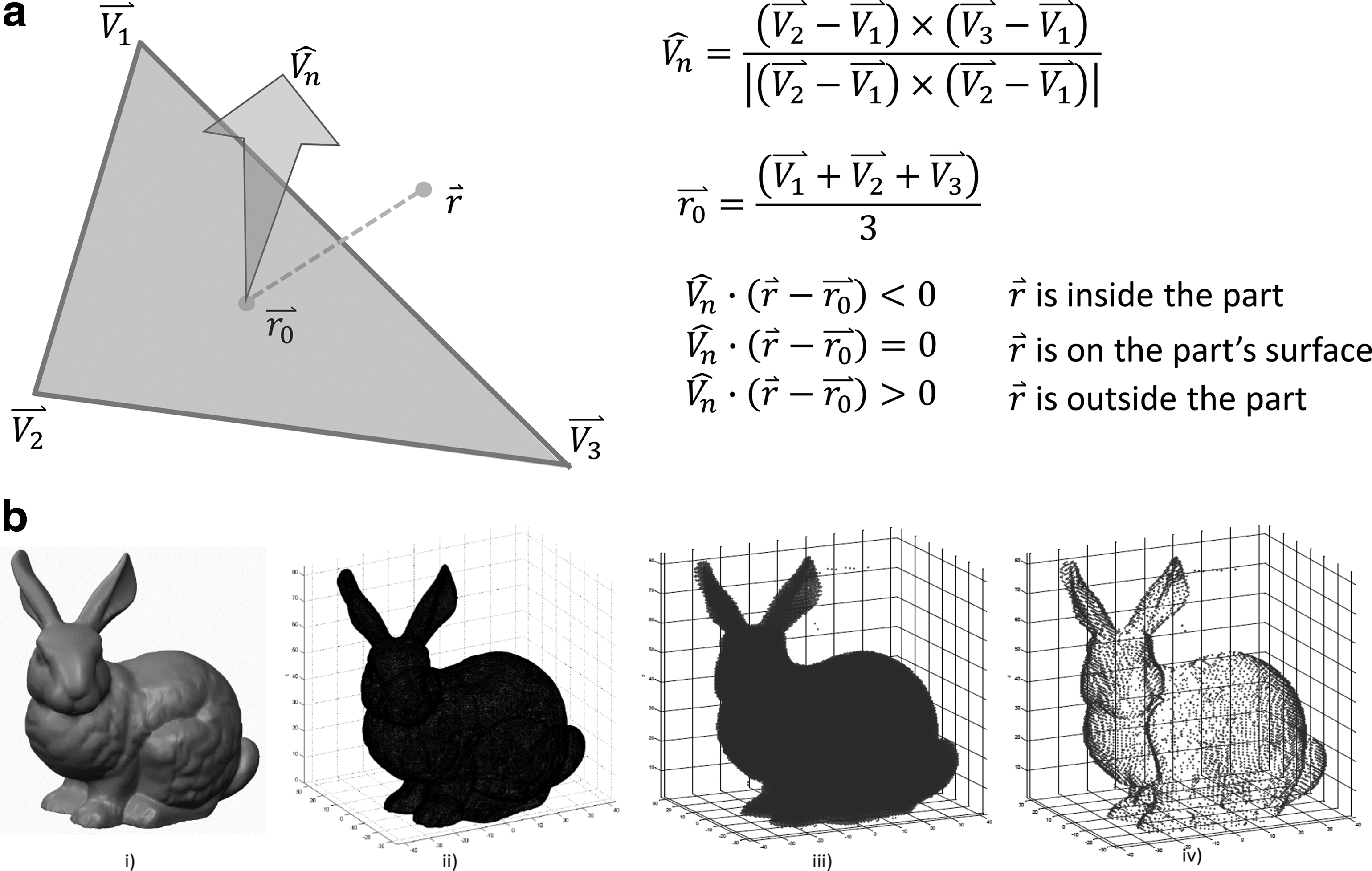
Programs to convert STL files into G-code, a tool path-based language used by many 3D printers today, are available commercially. G-code works well with single-material printers such as fused deposition modeling (FDM) printers. With multimaterial printers, different types of materials may require different deposition behaviors to ensure a good-quality final shape. These deposition behaviors include factors such as acceleration, deceleration, speed, and time delays to allow for material curing. To account for the need to have added functionality with multimaterial deposition, a solution was found by creating a separate MATLAB program that can be incorporated into the control program for the printer, and could output specific print commands when provided with an STL file. The MATLAB program reads in the STL data, and identifies the maximum and minimum X, Y, and Z values of the part. Within these points, a grid is created according to a user-defined resolution. A point-cloud plot of the part is created by identifying which points are inside the object and which are outside the object. This is determined by vector geometry and the process is explained in Figure 3.
This process of creating a point-cloud representation of a part is very similar to the process of voxelization. 14 Voxelization is a method of representing geometry, which gives information regarding its volume and not just its surface area. It is an attempt to address some of the limitations of representing geometry as a surface mesh. Some of these limitations include how to add additional information about a component other than its geometry. These limitations are especially visible with more advanced printers when additional material properties affect the printed component, for example, color, porosity, and cure method. The use of representing the geometry as a point cloud allows additional information to be supplied at each point in the point-cloud system, facilitating the printer to vary what material is used, how it is deposited, or any further information required to create the final component. The amount of information that can be added is not fixed and so as printer capabilities increase, this method will still be viable.
Once the program has identified the points inside the part, the points on the outer edge are identified for a specific Z value. This is done at each different Z value of the point-cloud part, creating a “shell file.” From the shell file, the nozzle path commands are created, building the part from the base up. The final output is an ASCII file read by the printer program. This process is demonstrated in Figure 3, using the Stanford bunny as an example object to be printed. This shape is used due to its irregular geometry, demonstrating the capability of the program. The resolution of the point cloud can be varied independently for each material in a part to account for the different nozzle capabilities.
Currently, the program requires each material part of the composite object to be uploaded as a separate file. This is a manual process and is one of the main limitations to using this process. An alternative way to automate this process is being explored such that the user can upload a single STL file and the program will recognize the different material parts of the composite object. This method requires each point in the point cloud being assigned a material number (i.e., 1, 2, or 3), which is determined by the STL facet used in the point's processing. The difficulty is correctly determining which facets belong to which material components without user intervention. As stated, this automation process is currently being explored.
Composite Material Design
To demonstrate the functionality of the printer, a three material component LRM was designed. An LRM is a periodic material that is currently being explored for its acoustic properties and is of interest to the scientific community who studies acoustics, as LRMs can be used to reduce unwanted noise and vibration. 12 An LRM typically consists of a spherical core, which is coated by an elastic lining, and held in place by a matrix material (Fig. 4). The optimal design for an LRM will have a high-density material for the core and a low-density but stiff matrix material. 15

Cross-section CAD file of the composite object to be printed (three LRM unit cells). LRM, locally resonant metamaterial.
When choosing the materials to use for the LRM, a series of materials were trialed on the printer to determine their ability to be deposited consistently as well as their final printed quality. Several factors were considered, including the material's ability to deform once deposited, the rate at which it could be deposited, and the curing methods.
The inkjet nozzles on the printer can only print materials with a low viscosity (20 mPa or less), but the benefit is that it is possible to print a component with a good final resolution (features printed can be as small as 80 μm). However, the time taken to print using these nozzles can be long as each droplet has a typical volume of only 2.145 nL. There is less restriction on a material's viscosity when deposited with the continuous nozzle, as a higher viscosity material will simply require a greater pneumatic back pressure to extrude it. Another benefit of the continuous nozzle is that it has the ability to deposit a relatively large amount of material in a short space of time, but the final resolution of the printed component may be lower.
For the continuous nozzle, various UV curable resins were trialed, including Silfort UVHC 3000LS®, VeroClear®, and Permabond UV625®. The Silfort UVHC 3000LS deposited well but on curing became very brittle and so was unsuitable for use. The VeroClear is a material used commonly as an epoxy-like material, which is light and stiff, however, when deposited, it had the tendency to run due to its low viscosity, meaning the deposited shape did not resemble the original design. VeroClear is used by the Connex range of printers by Stratasys. The Connex printers rapidly expose the material to UV light once deposited, significantly reducing the occurrence of material run-off. The custom-built printer is unable to replicate this rapid curing making VeroClear unsuitable for use.
Finally, the Permabond UV625 was trialed and this performed well. Its gel-like consistency meant it held its shape well before being cured. On exposure to 365 nm wavelength UV light (supplied by a UV torch), it cured as a stiff, durable material that could be handled without breaking, making it suitable to use as the matrix material for the LRM.
The elastic lining part of the LRM is typically rubber. Recent research had shown it was possible to print Litex T71S20® via the inkjet method. 9 More importantly, it was shown that viscosity was low enough to be printed at room temperature and heating was not required. As such, it was suitable to use on the room temperature inkjet device of the printer. Litex T71S20 is a latex rubber that cures by the evaporation of its solvent at room temperature. No other elastomer-type material was trialed using this nozzle.
Initial trials of printing rubber used the continuous nozzle. The material deposited was Momentive™ TSE397 silicone and this deposited well and cured at room temperature by evaporation of its solvent. Its semiflowable consistency meant it had too high a viscosity to use with an inkjet nozzle and hence was not used in the final print configuration.
The final material to be chosen was for the core. As the printer has a heated inkjet nozzle capable of reaching 240°C, the possibility of using low melting point alloys becomes viable. When various solders were examined compared to other polymers and ceramics that could be printed with this nozzle, it was clear that solder alloys had a significantly higher density, making them more suitable for the LRM. A solder with the composition Sn96.5Ag3Cu0.5 (henceforth referred to as SAC) was chosen as it had a melting point of 217°C, well within the range of the heated inkjet nozzle, but also a low enough viscosity to be jetted. The solder is first preheated to remove any flux and then cooled. Once the flux had been removed, the solder alloy can be melted in the reservoir of the nozzle. It then passes through a 7-μm stainless steel filter and finally into the inkjet nozzle. Once deposited, the solder solidifies on cooling.
The physical properties for each of the materials chosen for the printer, and their corresponding nozzles, are shown in Table 1. The final geometry of the LRM cubic unit cell has lengths of 5 mm. The core is 3.4 mm in diameter and has a 0.55 mm thick elastic layer as the coating component of the metamaterial (Fig. 4). It was decided to print the LRM as one row with three unit cells to allow the LRM to be acoustically tested at a later stage (not performed as part of this article).
Results
The proposed design was developed using the CREO Parametric 3.0 CAD system, and the geometry was processed, as outlined in the Geometry processing section. Each material was printed individually to check that it could be deposited as intended.
An issue arose when printing with the heated inkjet device, through which the droplets of solder cooled too quickly once jetted, resulting in a printed object with a consistency more similar to a powder rather than a solid object. Different printing setups were explored, including moving the nozzle closer to the substrate to reduce the time taken for the droplets to reach the printed object. A shield was also trialed, through which some foil was placed around the nozzle to restrict air flow and reduce the rate of cooling of the droplets, but this did not achieve its desired result. In an attempt to create larger droplets, a blocked nozzle had its tip cut off and then placed in the printer to trial printing with the solder. It was not possible to create the droplets as intended, but it was observed that large droplets of solder formed at the tip of the blocked nozzle due to a low pressure in the nozzle's reservoir and gravity acting on the solder. When these droplets fell, they remained molten for a short time after reaching the glass substrate. This hybrid approach to depositing the solder proved to be viable when printing the LRM as the core of the composite remained as one solid object.
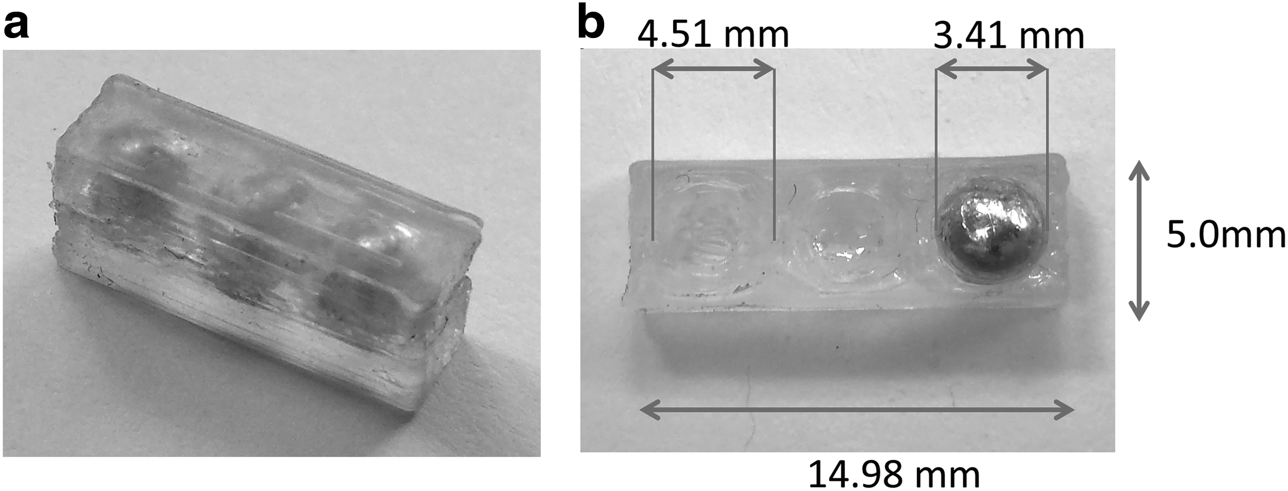
With this hybrid approach, LRM composites were successfully printed. The printed objects can be seen in Figure 5. The composite object was printed by first depositing the matrix material, up to half the height of the unit cell, followed by the rubber. Once the rubber had cured, the molten solder droplets were deposited into the cavities and allowed to cool. The rubber was then deposited on top of the core when cooled to create the rest of the coating part of the metamaterial. After this was completed, the matrix material was deposited to finally create the composite LRM object. The time taken to make one of these composite metamaterials was just over 5 h. The long print time was not only due to the time taken to deposit the various materials but also time had to be allocated to allow the various materials to cure, and to perform purges and cleaning of the nozzle tips to prevent clogging. In addition to this, the process of printing from point-to-point, as required by the point-cloud method, did increase the time taken to print due to the increased number of acceleration and deceleration cycles. The final print settings used are shown in Table 2.
Discussion
Several interesting observations were made during the printing process. The Permabond UV625 UV curable adhesive has a gel-like consistency and maintained its deposited shape well when printed on a glass substrate until it could be cured. With the 250 μm nozzle diameter fitted, a back pressure of 5 psi, and a nozzle speed of 2 mm/s, the Permabond material was deposited with a height of 150 μm and a width of ∼450 μm. However, there is a noticeable bumpy appearance at the ends of the printed object. It is believed that this is due to excess material coming through the nozzle as it pauses between depositing different lines of material. This issue could potentially be resolved by increasing the vacuum pressure applied at the end of each deposit, and reducing the time taken for the nozzle to move from one line to the next. A smaller nozzle tip could also be used to allow for smaller feature sizes. A 100-μm nozzle was tried, which produced a line with a much thinner profile, but resulted in much longer printing times, too impractical when attempting to print larger objects.
The room temperature inkjet nozzle deposits the Litex T71S20 rubber. This is a material which, when mixed with a small amount of triethylene glycol monomethyl ether (TGME), has successfully been printed using an inkjet method. 9 The TGME is used to delay the drying time of the rubber to stop the material getting clogged in the nozzle and to reduce the chance of agglomeration of the colloidal solution. However, it was noticed that the curing times (at room temperature) of the rubber with the TGME added did significantly increase when compared to deposited samples of rubber with no TGME added. As such, it was decided to print with the Litex T71S20 material without being mixed with the TGME. This reduced the curing times between each deposited layer to a matter of a few minutes rather than 20–30 min. In instances where the nozzle was blocked, the printing process was paused, a small amount of toluene was applied to the tip of the nozzle, followed by short purging of the material through the nozzle, and the print was then continued. The toluene was recommended as it causes the rubber to expand and soften to allow it to be forced out easier with air pressure. This presented an issue as it required close supervision of the nozzle as the rubber was being deposited. The time taken to print can be adjusted using the settings in the LabVIEW program, and so, it is hoped that by speeding up the nozzle speed, and reducing the delays between depositing each line of the rubber, the need to unblock this nozzle will not be a problem.
The SAC solder was deposited using the Polymer Jet™ nozzle. The system's nozzle and reservoir device was heated to 225°C, which melts the solder, a process that takes ∼20 min before printing. The molten solder then passes through a 7-μm stainless steel filter to remove any particulates or debris in the reservoir. The hybrid approach of depositing the solder via the formation of large droplets (described in the Results section) did allow for the creation of the solid spherical core. However, there is doubt this method could be used if the cavity to be filled was of a more complex geometry. For example, if the cavity was cuboid rather than spherical, it would have to be seen if the molten solder would fill the entire space, or would gaps be present near the corners of the cuboid. In the future, an alternative material will be trialed to allow normal droplet formation with the heated inkjet nozzle.
When the boundary between the rubber and matrix parts of the printed LRM was examined under a microscope, they showed good adhesion between the two with no air gaps visible. This was consistent with prior printing trials of the two materials. The boundary between the rubber and the solder showed less adhesion. Again, no air gaps were visible under a microscope, but little physical effort was required to separate the core from the lining. This limits the use of using the solder and rubber material again in the future for different geometries if the different material components can be easily separated.
Taking an overview look of the process, the printer proved capable in fabricating the composite material designed and confirmed the functionality of the control program and geometry processing methods. The build did take approximately 5 h to print the block of three unit cell LRMs. This is a long time to print a relatively small object. As there are different cure methods for each of the materials, the print process had to be paused to allow rubber and solder to dry and cool, respectively, and the use of the point-cloud method means there are additional acceleration and deceleration cycles during the print. The UV curing method was the quickest, taking a matter of seconds to harden the resin. Many commercial multimaterial printers adopt a purely UV cure method for this exact reason, but the drawback is that it does limit what materials can be used. The final printed composite object does resemble the original proposed design well. The small discrepancies in the geometry of the printed part were within design tolerances, giving credibility to the use of the printer for future use with different materials and geometries. More importantly, it does show that the direct-write techniques used are capable and effective for multimaterial printing, and are promising for the development of more capable multimaterial printers in the future.
Conclusion
A custom 3D printer, which utilizes both continuous direct-write and inkjet printing methods to print three different materials in one object, was designed, built, and tested. The materials printed are Permabond UV625 UV cure adhesive, Litex T71S20 rubber, and Sn96.5Ag3Cu0.5 solder. The use of direct-write printing techniques facilitates the use of a wider range of printing materials than alternative printing methods. The printer is controlled by a custom-made LabVIEW program that allows all aspects of the print process to be controlled and customized. The program uses a point-cloud method to process a part's geometry and copes well with multiple material models but does require user input to do so. The final printed component resembles the original CAD design well. Some small defects were visible in the final print but could be mitigated by the alternative print settings described in the Discussion section. As future work, alternative materials will be used in the heated inkjet to allow normal droplet creation and alternative composite designs can be explored to examine how well the printer can cope with more irregular geometry. In addition, further development of the geometry processing method is needed to allow the user to upload a single STL file and for the program to recognize the different material components in the multimaterial object.
Footnotes
Acknowledgments
The authors thank DSTL and The Royal Academy of Engineering for the provision of resources to make this project possible, and Synthomer for the supply of Litex T71S20 samples to facilitate this research. They also acknowledge Dr. Raymond C. Rumpf for outlining a method for converting an STL file to a point-cloud file in correspondence.
Author Disclosure Statement
No competing financial interests exist.