
Abstract
Abstract
The purpose of this article is to investigate the possibility of manufacturing a digital hydraulic valve system using additive manufacturing and to identify the challenges and benefits of doing so. In this study, an existing hydraulic valve manifold, operating at pressures up to 25 MPa, was redesigned for selective laser melting (SLM) and further optimized with computational fluid dynamics. Certain dimensioning challenges were encountered because laser melting is not yet accurate enough for some features, but these challenges were circumvented. The manifold was successfully manufactured from tool steel and tested for maximum operating pressure and flow capacity. Due to the improved flow channels, the selective laser melted manifold provided up to 49% reduction in the energy losses caused by flow resistance. This article demonstrates that SLM can be used to improve the performance of hydraulic valves and that the cost of SLM manifolds is feasible for high-end valve assemblies.

Introduction
D
A digital valve system includes several metering edges, each of which are controlled by a number of on/off valves. These kind of valve systems have been used, for example, to improve reliability of train tilting mechanism 2 and to improve performance of paper machinery. 3 There are, however, very few commercial digital hydraulic valve systems available. One reason for this is that digital valve systems are commonly built by mounting commercially available cartridge-type on/off valves to a machined manifold, which results in a large and heavy valve system with slow response. An example of such a valve system containing 24 on/off valves is shown in the background of Figure 1.
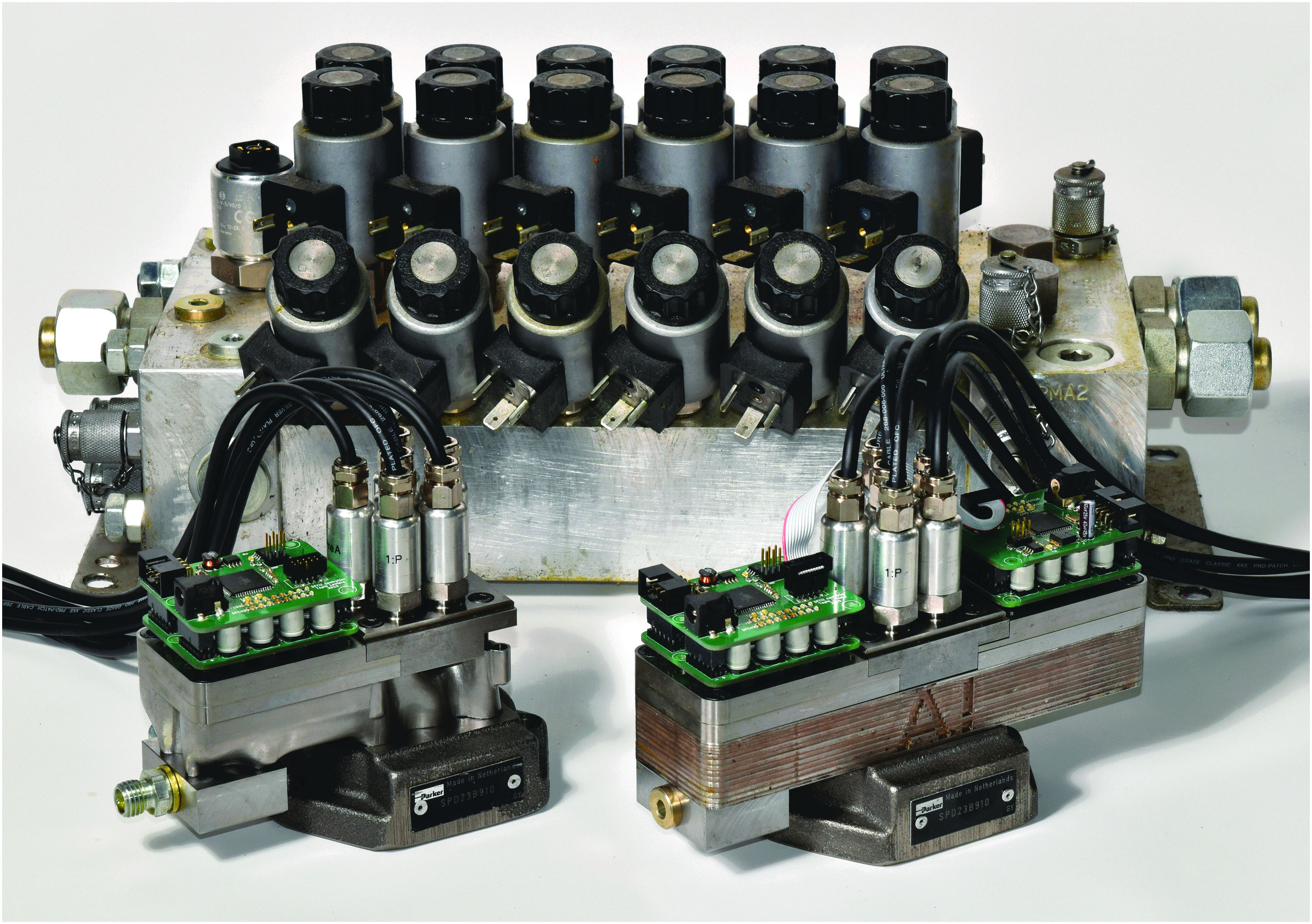
On the left a digital hydraulic valve system with selective laser melted manifold. On the right the previous prototype with a laminated manifold. In the back, a 24-valve digital hydraulic valve system built using cartridge valves.
To make digital valve systems, a feasible alternative for proportional valves in a wider area of applications, their size must be reduced. Research into miniaturizing digital valve systems has been conducted for close to 10 years now and it is ongoing.4–6 Miniaturizing the individual on/off valves reduces the dimensions of the valve systems or enables including a larger number of valves in a certain sized valve system, thus improving the control resolution of flow rate and the motion of hydraulic actuators. Miniaturizing also generally leads to improved response time of the valves. Figure 1 shows the front two digital valve system prototypes from the authors' research group. The prototype on the right side of the figure is the valve system used as the basis of the research presented in this article. It contains 32 on/off valves that control four metering edges, thus making functionality roughly equal to commonly used 4/3 proportional valves. Even though the prototype is a fraction of the size of the digital valve system at the back of the figure, its flow capacity is similar and its response time is far better. 7 The left side of Figure 1 shows the 16-valve digital valve system, which is the result of the research presented in this article.
The inherent problem in miniaturizing digital valve systems and increasing the number of included valves is that flow channels and other features in the system become smaller and more complex. This can lead to manufacturing problems, which render conventional manufacturing methods of flow channels such as drilling, milling, or even casting infeasible. Therefore, unconventional methods such as laminating a manifold from metal sheets have been previously used.8,9 Laminated object manufacturing (LOM) enables the manufacturing of very small and complex flow channels but it also has several drawbacks, further discussed in the following chapters, which reduce the performance of laminated manifolds. Thus, the authors turned to selective laser melting (SLM) of the valve manifold as a means for improving the performance of the valve system.
There have been several efforts to improve hydraulic components by redesigning them for SLM in recent years. Renishaw Plc. published a case study in 2016 in which they redesigned a complex hydraulic valve and measured a mass reduction of 79% and an improved flow efficiency of 60%. 10 VTT Oy released a similar study in 2016, in which they presented a detailed process flow of topologically optimizing a complex hydraulic block and manufacturing it with SLM. The weight reduction in this case was stated to be 76%, but no increase in performance was reported. 11
Peer-reviewed research in additively manufactured hydraulics has so far been limited. Cooper et al. found that redesigning a conventional hydraulic component consisting of two channels for additive manufacturing (AM) resulted in up to 250% improvement in flow rate. 12 Aside from this single publication, most research efforts concerning hydraulic valves, such as Wei et al. and Farré-Lladós et al., have been aimed at miniaturization of hydraulic channels to microlevel with the help of AM.13,14 These channels are not designed to withstand more than a megapascal of pressure, and therefore cannot be used in fluid power applications, where operating pressures are commonly 20–40 MPa.
On the contrary, the use of AM to create conformal cooling channels in tool production is widely spread and a significant amount of research is focused on it. Brooks and Brigden conducted a case study in 2016 in which they reported an increased productivity of 19%. 15 Ilyas et al. found that conformal cooling could increase productivity in ideal cases by 59%. 16
Reference Model
A previously manufactured laminated manifold was used as the basis for the selective laser melted manifold. This reference model is a manifold for a digital valve system prototype consisting of 32 pilot-operated miniature valves. The manifold contains four individually controlled metering edges, each of which contains eight parallel connected on/off valves with four different orifice sizes. In addition to the main flow channels, there are smaller flow channels inside the manifold for providing the supply pressure and tank channels for the pilot stages of each of the 32 valves. The dimensions of the manifold are 176 × 49 × 24 mm and it functions as a part of a valve assembly shown in Figure 1. In addition to the manifold, the assembly contains four machined layers, two small moving parts, and a coil for each on/off valve and integrated valve control electronics.
The manifold consists of 14 layers of 1- and 2-mm-thick laser cut AISI 316L stainless steel sheets. The sheets are vacuum brazed together to form a solid block with most of the flow channels inside. Since laser cutting does not produce a sufficient surface quality for any sealing or sliding surfaces, features with this kind of functions were machined after brazing. Figure 2 shows a model of the laminated manifold as well as the sheets it consists of.
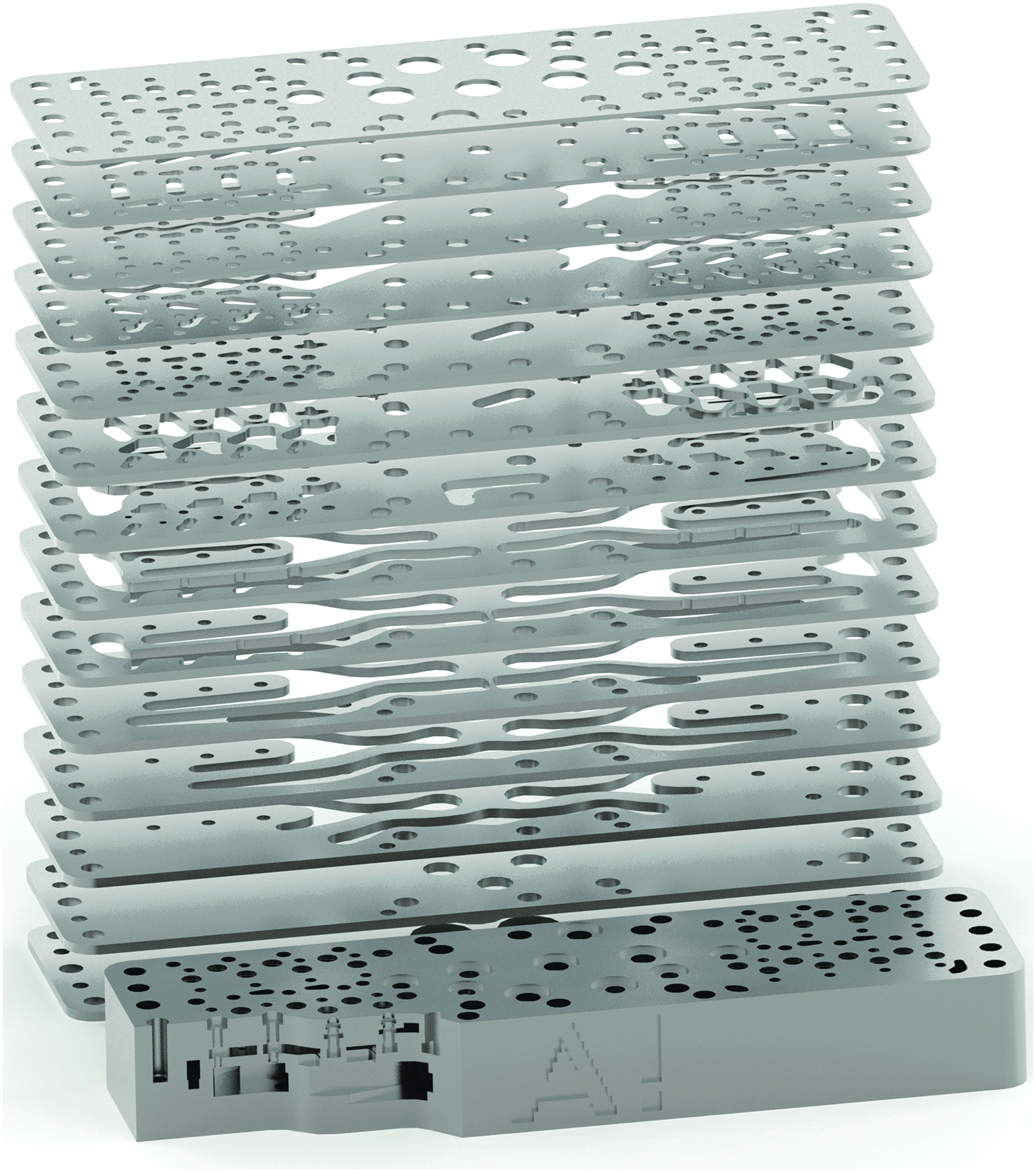
Partially cut view of the laminated manifold and the sheet metal layers it consists of.
This production method allows a flow channel to curve smoothly in the horizontal plane. However, when inclined upward, the channel walls have discrete vertical steps caused by the sheet thickness. Since the utilized sheet thickness was mainly 2 mm and the diameter of the largest flow channels in the manifold is ∼8 mm, for example, a round cross section of a horizontal channel can be represented only coarsely. In the laminated manifold, the sheets were cut with a 2D laser cutter, and therefore, the edges of the sheets are vertical. Utilizing a 3D laser cutter for bevel cutting, the edges of the sheets could improve the smoothness of the shapes. Using thinner sheets would also improve smoothness but would increase the complexity of manufacturing as well as the number of brazing joints where faults leading to mechanical failure of the manifold or leakage could be present.
The lamination method also imposes other restrictions on the design. For example, there cannot be a detached island inside a sheet layer since it might not maintain its correct position during the brazing process. The stack of sheets is also under some vertical compression during the brazing process, which can deform long and thin vertical walls, since the metal sheets soften at high temperature. Therefore, long cuts that create slender bridges through the sheets should be avoided. 17
The vacuum brazing process also affects the mechanical properties of the sheet material. Brazing is done at a temperature of 1100°C where the copper used as a brazing alloy melts. This high temperature and slow cooling in the vacuum oven bring the base metal to its fully annealed condition, which reduces its hardness and yield strength. Hardening could be completed after brazing and machining but it might slightly deform the shape of the final product.
The laminated valve manifold has been tested to function properly. Even though the flow capacity of the prototype valve system already exceeds that of similar sized commercially available proportional valves, pressure losses inside the main flow channels are large and thus limit the flow capacity and cause energy loss. When designing the laminated manifold, computational fluid dynamic simulations were not used to improve the channel geometry; however, the limitations caused by the manufacturing method would likely have allowed only minor improvements. Therefore, the design freedom enabled by SLM was considered as a solution to improve the flow properties of the valve system.
Design of New Geometry
The new geometry contains two metering edges, each with eight valves, instead of the four metering edges in the laminated manifold, and thus, it is approximately half the size of the reference part. The size reduction was done to limit the required design effort and production costs. The included metering edges control fluid flow from a high-pressure inlet to an actuator outlet (metering edge P–A) and from the actuator outlet to a low-pressure tank line (metering edge A–T).
To maintain comparability between the laminated and selective laser melted manifolds, they are both assembled using the same additional parts to make up the digital valve systems. Therefore, the mating surfaces between the manifold and the rest of the parts had to remain unchanged in the new geometry. The rest of the geometry for the new model was completely redesigned, since the laminated model was designed specifically for the lamination method and manufacturing it with SLM without modifications would not have yielded most of the AM benefits.
Figure 3 shows the internal geometry of the selective laser melted manifold on the left and for comparison the geometry of the laminated manifold on the right. The smallest flow channels inside the manifold have a diameter of slightly over 1 mm and the thickness of the thinnest walls is slightly less than 1 mm. Manufacturing these features with SLM is not a problem. However, each of the 16 pilot valves has one sealing surface inside the manifold, which has to be at a distance of 3 mm from the top surface and parallel to it. This surface is a metering edge for the pilot valve and can only be accessed through a bore with 2.3 mm diameter and thus it is difficult if not impossible to machine. The original tolerance limits for this 3 mm distance were +80 to −20 μm. This kind of tolerance is difficult to reach with SLM since the lower distance tolerance is similar in scale to the achievable surface roughness. The achievable geometry tolerance according to the material manufacturer and the service provider was ±50 μm. 18 Because this was larger than the lower distance tolerance, the nominal distance was increased by 30 μm in order for the tolerance not to drop outside the accepted zone. Since the manifold was manufactured with a layer thickness of 50 μm, steps caused by the layer thickness were also unacceptable on this surface. Therefore, the build orientation was chosen as shown in Figure 3 to get an acceptable surface roughness on both the top surface manifold and this difficult sealing surface.

Flow channels inside the selective laser melted manifold (left) and the laminated manifold (right). High-pressure inlet channel in red color, actuator outlet in yellow, and low-pressure tank line in green. The manifolds also contain pilot pressure supply channels (blue and orange) and pilot tank channels (green).
Another challenge presented by the change of manufacturing method from LOM to SLM is related to overhanging structures. Normally, overhanging structures can be produced with SLM by making support structures underneath them. However, in this case, channels had to be designed in such a way that no large overhanging structures would be present, because internal supports would be impossible to remove. To solve this issue, the build direction was decided early in the design stage so that all internal features could be designed to be manufactured without internal supports. To ensure that all sealing or sliding surfaces would be properly machined, a machining allowance of 0.2 mm was added onto them and round profiles larger than 2 mm, which were horizontal in build direction, were changed to the shape of a droplet. The design for additive manufacturing guidelines of element transitions presented by Adam and Zimmer was used as a basis for verifying the redesign of the manifold for manufacturability. 19
The target operating pressure for the digital valve system was 25 MPa. To ensure the structural integrity of the manifold when operating under high pressure, mechanical stresses in the manifold were simulated with PTC Creo Simulate 3.0. Due to the placement of the features that remained unchanged from the laminated model, there are small corners in the manifold where relatively high stress peaks occur. Therefore, the material chosen for the manufacturing of the selective laser melted manifold is EOS Maraging Steel MS1, which provides a high yield strength of 1000 MPa in the selective laser melted condition as well as relatively good hardness and machinability. 18
Even though digital valve systems control the flow of hydraulic fluid by throttling it, that is, by restricting the fluid flow by causing controlled pressure loss in the orifices of the valves, maximal flow capacity is desired when all of the valves in a metering edge are opened. Therefore, the flow channels leading to the orifices should not cause significant pressure loss even at the maximum flow rate of the metering edge. The design freedom enabled by SLM makes it possible to optimize the shape of the flow channels to reduce the pressure loss in them.
Computational fluid dynamics (CFD) was used to simulate the flow of fluid inside the manifold. Since mathematical optimization of such complex channels would have been very difficult and computationally expensive, the shape of the flow channels was improved iteratively by simulating a certain geometry and improving it manually according to the simulated flow field. The target was to decrease the pressure loss between the inlet and outlet ports for each metering edge in the situation where all of the eight valves are open. This is when the flow rate is largest and energy loss due to the pressure losses in the main flow channels can be major. In practice, pressure loss was reduced by eliminating areas where the flow separates from the channel walls or flows backward by shaping the channel walls according to the streamlines of the fluid flow. CFD simulations were performed with Ansys Fluent using a 3D representation of the fluid volume between the inlet and outlet ports of one metering edge. Two separate cases were simulated; one where fluid is flowing from pressure supply P to actuator channel A and one where fluid flows from actuator channel A to tank channel T.
Since the fluid flow inside the manifold is mostly turbulent, choosing a suitable turbulence model for the simulations is important. To limit the computational effort required by the simulations, a time stationary solution and a Reynolds-averaged Navier–Stokes (RANS) turbulence model was utilized. RANS models represent the energy loss caused by the eddies in the turbulence as an additional viscosity term. The chosen RANS turbulence model was realizable k-epsilon, which is an improved version of the widely used k-epsilon model. The meshes representing the fluid volume consisted of ∼2.5 to 3 million mostly hexagonal cells, and the boundary mesh thickness was set to be suitable to solve the turbulence model also at the channel walls.
The CFD simulations were performed with a velocity inlet boundary condition, which corresponds to a flow rate of ∼87 L/min. According to the simulations, metering edge P–A in the laminated manifold has 3.4 MPa of pressure loss with all the valves opened, while the selective laser melted model has a pressure loss of 2.2 MPa. Corresponding values for A–T metering edge are 4.2 and 2.6 MPa. This suggests a 35–38% reduction in the pressure loss across the metering edges.
Figure 4 shows the streamlines of the simulated flow field in the metering edge P–A of the selective laser melted manifold and the laminated reference manifold. The color of the streamlines represents the velocity of the fluid. To make the comparison between the laminated manifold with four metering edges and the new manifold fair, the shown simulation result includes in the top left corner also the pressure supply channel to the metering edge P–B that in reality is not present in the selective laser melted prototype. This additional branch of channel creates a vortex that increases the pressure loss; however, according to the simulations, this increase in loss is minimal.
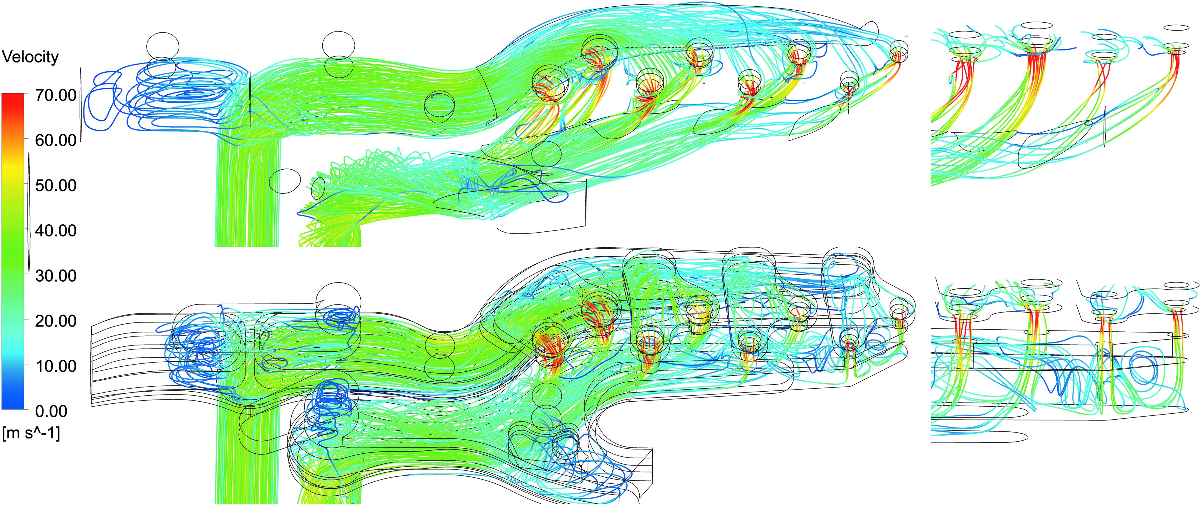
Simulated streamlines of fluid flow in the P–A metering edge of the selective laser melted (top) and laminated (bottom) manifolds. The right side shows a detailed view of the fluid jets at the orifices of the four smallest valves.
The simulated streamlines of the laminated manifold show several areas of flow separation, backflow and swirling flow. All of these add to the large pressure losses in the flow channels. A clear problem in the laminated manifold is that the orifices of the valves are short vertical bores that direct the fluid jet directly at the opposing channel wall, creating strong vortexes as shown in the detail view of Figure 4. The lamination manufacturing method prevents aiming these jets differently. In the selective laser melted manifold, it was possible to create a dedicated smoothly curving outlet channel for each of the orifices to direct the fluid flow along the main flow channel. This enabled a significant reduction in the pressure losses.
Physical Prototypes and Tests
Before manufacturing the final part, a plastic version of the new design was manufactured using a Form2 stereolithography printer and the operation of the valve assembly was successfully tested with 0.7 MPa of pressurized air. The tool steel manifold, shown in Figure 5, was procured from an AM service provider at the cost of 901.50 €.
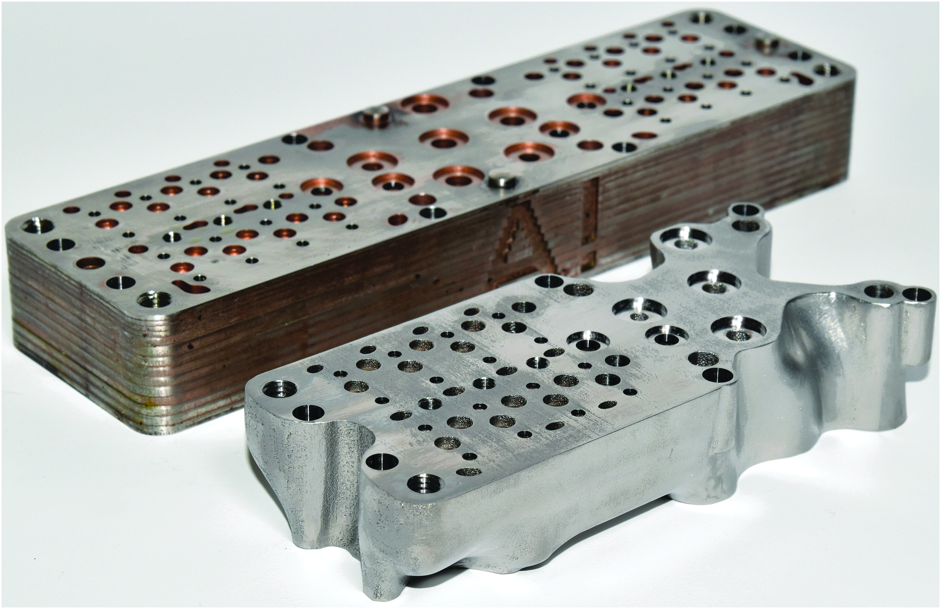
In the front, the selective laser melted manifold. In the back, the laminated manifold.
The flatness of the top face of the tool steel manifold and the distance between the pilot valve metering edges and the top face were measured with a coordinate-measuring machine. The flatness of the critical area surrounding the on/off valves was sufficient. However, outside of the critical area there were peaks, resulting in an overall flatness of 130 μm, which would impede the assembly of the valve. The peaks were removed by lapping to achieve better overall flatness. The final distance between the pilot valve metering edges and the top surface was 3.00–3.06 mm, which was inside the tolerances discussed in chapter 3.
All functional holes in the surface of the valve were machined to achieve a sufficient surface roughness and accurate geometrical tolerances for the orifices, and any sliding and sealing surfaces.
The operation of the valve system was tested up to the designed maximum operating pressure of 25 MPa. Flow capacities were tested for each of the valves individually as well as for completely open metering edges. The valve test setup was the same as used previously in testing the valve system prototype with the laminated manifold. 7 The flow rate through the metering edges P–A and A–T was measured with Kracht VC5 gear-type flow meter while monitoring the pressures in P, A, and T channels.
The measured pressure difference over metering edge P–A in the selective laser melted manifold at a flow rate of 87 L/min was 1.9 MPa, while the simulated pressure difference was 2.2 MPa. Corresponding values for the laminated manifold were 3.7 and 3.4 MPa. The differences between the measured pressure losses and the simulated ones are ∼10%. The pressure loss in metering edge P–A of the selective laser melted manifold is approximately 49% smaller than the corresponding loss in the laminated manifold. With the current test setup, A–T metering edge of the laminated manifold could not be tested at this flow rate so a direct comparison cannot be made.
Table 1 shows the measured flow capacities of individual valves in metering edge P–A. Aside from the smallest valves, the flow capacity of the valves in the selective laser melted manifold is on average 30% larger than the corresponding one in the laminated manifold. Smallest valves do not show an increase since small flow rates do not cause significant pressure loss even in inefficient flow channels, and therefore, the orifice of the valve is the main source of pressure loss. Results for metering edge A–T are similar.
SLM, selective laser melting.
Discussion
The main benefit of SLM in the production of the digital hydraulic valve manifold was the significant performance improvement it enabled by making it possible to shape the flow channels according to the CFD simulations without the limitations of the previous manufacturing method. In addition, the selective laser melted valve was lighter than its laminated counterpart and its material is harder, improving the durability of the sealing surfaces. The laminated manifold in turn has the advantage of better surface quality in the flow channels, especially at overhanging structures. However, the benefits of this better surface quality are clearly outweighed by the design limitations. Furthermore, the internal surface quality of SLM components can be improved by using hybrid-manufacturing machines, in which each layer is machined after it is selective laser melted. However, the price of hybrid manufacturing machines is currently high and it is challenging to find service providers for this technology.
Because SLM can adapt itself to new designs easily, slight changes can be made in the valve system without the need to re-evaluate the supports or change the nesting. Such changes can include, for example, changing the size of the valve orifices to customize their flow rates for different applications. Such options of mass customization would have no effect on the cost structure of selective laser melted valves and would cater to the needs of the customer more precisely.
If performance of the valve systems is the only metric by which the manufacturing technology is decided, SLM is the clear choice because it can produce manifolds that are more efficient and durable. However, there are several economic considerations to take into account when deciding whether to produce a digital hydraulics manifold with SLM or with lamination.
The production chain of lamination involves four stages (cutting, copper coating, brazing, and machining), while the chain of SLM involves only three (SLM, postprocessing, and machining). Of the three steps in SLM production, the SLM process itself and the postprocessing are usually done at the same facility. Conversely, very few places are equipped with all the necessary machinery for lamination, therefore complicating its production chain. The initial cost of the lamination method is quite high because of the amount of logistics and manual labor necessary, but drops to a fraction of the original cost when producing larger series. For SLM, the outsourcing price is composed mainly of machine hour price, high material price, and work involved with preprocessing the part. According to the service provider that manufactured the manifold for this study, the initial cost of ordering selective laser melted manifolds is reduced to approximately a third when subcontracting series production. Ultimately, the economic benefit of SLM is the simplicity of the production chain, while the benefit of lamination is the reduction of per-unit costs in high-volume production. An important aspect to consider is the cost of the final assembled valve unit. Because the cost of the valve assembly is high compared with the cost of the manifold, the increased cost of SLM is acceptable since the manifold increases the performance of the entire unit.
The design of the manifold in this study was restricted by the design of the previously existing laminated manifold. If the whole valve assembly were to be designed for SLM from the beginning, some of the features of the manifold could be moved to the other layers of the valve assembly while retaining the performance benefits of SLM. This would reduce the volume of the selective laser melted components, thus making SLM an even more competitive manufacturing method.
Conclusions
A pre-existing laminated manifold for a digital hydraulic valve system was redesigned for SLM, manufactured, and tested for this study. The results were favorable and show promise for the future of SLM in digital hydraulics. The selective laser melted part showed significantly improved performance over the laminated prototype. This shows that SLM can improve the performance of hydraulic components, especially in cases with small and complex flow channels such as digital hydraulic valve systems.
The process of manufacturing digital hydraulic valves with SLM is shorter and simpler than with lamination. SLM also imposes much fewer limitations to the design process compared with laminating method. The cost of producing a single prototype is similar between both manufacturing methods but lamination is significantly more cost effective in series production. Even though SLM of valve manifolds in larger quantities has a higher cost than the laminating method, the cost is still considered feasible for commercial production of high-end hydraulic valves.
Digital hydraulics is an emergent field that is still looking for ways to design and manufacture its products. We hope that with the results of this research, the contributors of the field consider SLM as the preferential technology to produce digital hydraulic valves.
Footnotes
Acknowledgment
The funding for the laser melted part came from the Digital spare parts (DIVA) project funded by a consortium of companies and Tekes, the Finnish funding agency for innovation. The research was also funded by the Academy of Finland project Digital Hydraulic Hybrid Actuators, decision no. 278470.
Author Disclosure Statement
No competing financial interests exist.