




Abstract
Abstract
In this article we present a biomimicking skeletal muscle actuator for prosthetics to overcome the issues of high operating temperatures, low contractile strain, complexity, high weight and cost, and linear output as seen with current and academic prosthetic actuators. The actuator proposed is a fuse filament fabrication (FFF) printed shape memory polymer (SMP) actuator that has nonlinear contractile and passive forces, contractile forces and strains comparable with mammalian skeletal muscle, reaction time under 1 s, low operating temperature of 70°C, and has a low mass (74.0 mg), volume (46.74 mm3), and material costs of $0.0098 per actuator. The FFF actuator is a SMP melt blend composite of polylactic acid and thermoplastic polyurethane with a mixture ratio of 7:3. The FFF actuator here has nonlinear contractile properties that have peak contractile stresses ranging from 0.58 to 0.17 MPa for 100–60% applied strains, respectively, where mammalian contraction values range from 0.1 MPa (typical/average) to 0.45 MPa (maximum). In addition, the optimal strain of 60% has a strain recovery of 29.2%, which is comparable with the 20% for typical mammalian skeletal muscle strains. The actuator material was first characterized with Fourier transform infrared spectroscopy, scanning electron microscope (SEM), and tensile testing to determine the quality of extruded filament followed by force generation and strain recovery. Lastly, the FFF actuator was tested for thermal degradation and layer adhesion with SEM and differential scanning calorimetry (DSC) testing. SEM imaging revealed that there are layer separations throughout the actuator and DSC showed thermal degradation caused by oxidation and random chain scission due to thermal cycling.

Introduction
I
This article focuses on the development of a biomimicking skeletal muscle actuator for upper limb prosthetics. Actuators are used to provide movement and force to joints within a prosthetic device. For upper limb prosthetics, this would include digit/wrist manipulation, grip force, and rotation at the elbow. To achieve these types of outputs, an actuator that provides linear output or translates rotational energy to a linear force/direction is needed.
For upper limb amputations, current prosthetics use either a body-powered system or an electric/intelligent system. Body-powered prosthetics use a system of cables and pulleys that allow the user to actuate the prosthetic with the use of an intact anatomical system. Body-powered systems are lightweight, inexpensive, and lack complexity, but have no feedback system or high force output. Whereas electric systems use high powered DC/servo motors with a feedback/control system that collects input from electrodes monitoring muscular (electromyography [EMG]) or neural (electroencephalography [EEG]) activity. The downside to electric systems is that they are expensive, heavy, and generate noise pollution. For example, EMG control hands can weigh between 31.75% and 86.5% more than the average human hand,10,11 making it difficult/uncomfortable to wear since the weight is being applied to soft tissue instead of the skeletal system.
Both body- and electric-powered systems cannot provide an actuated motion that mimics bulk skeletal muscle. This is due to the motors providing a linear output and the body-powered system using rigid cables to transfer force and motion, which generates a linear output, where bulk skeletal muscle generates a nonlinear output under contraction/active and passive movements.
To overcome the issues with current actuators, academic research has developed many different types of actuators that include pneumatic or soft robotic actuators, shape memory alloys (SMAs), large thermal expansion materials, combination mechanical and tissue-engineered systems, thin films, nanofibers, and shape deposition manufactured actuators.12–21
Pneumatic or soft robotic actuators12,13 use compressed air or fluid to transfer into specific chambers within an actuation system, where the chambers are independent of one another. This allows the system to fill specific chambers with fluid and creates a structure that deforms to grasp/move objects. The down side is that these systems are complex, require a source of compressed fluid, and can be heavy compared with their size.
SMAs and thermal expansion materials14,15 can generate high force per weight characteristics with heat by changing microstructure orientation/phase or by reversible, directional thermal expansion, where SMAs have the benefit of being able to memorize a shape and then recover back to its memorized shape when deformed.
Both materials require high temperatures, up to 120°C, for actuation/displacement, which can decrease actuation response time, and have low strain recovery, where SMAs can only achieve a maximum of 8%. In addition, thermal expansion materials require a load to hold it in a deformed position so it can recover the shape when heated.
Lastly, mechanical/tissue-engineered, thin films, nanofibers, or shape deposition manufactured16–21 actuators have been used to create actuators but either require living skeletal muscle cells, complex nanowire/fiber manufacturing, and structure or require embedded electronic components. Actuators with living cells or nanofibers can generate high or physiological comparable strain rates, but have living cells that need nutrients and require complex manufacturing. In addition, current shape deposition manufactured actuators still require the use of embedded electronics during the printing process to create an actuator, but these actuators still provide a linear output.
To overcome the issues of high operating temperatures, low contractile strain, complexity, high weight and cost, and linear output, we propose a fuse filament fabrication (FFF) three-dimensional (3D) printed shape memory polymer (SMP) actuator that has nonlinear contractile and passive forces, contractile forces comparable with mammalian skeletal muscle,22–27 reaction time under 1 s, low operating temperature, high contractile strain, and low cost, mass, and volume.
SMPs are able to recover a predetermined/memorized shape (shape memory effect) by shaping the polymer at room temperature or in its glass transition (Tg) temperature range. Using the Tg allows the polymer to be easily shaped/deformed since the polymer has transitioned from a hard/glassy state to a soft/rubbery state, where the polymer chains can be rearranged. The polymer is then cooled (shape fixity) in its deformed shape until it returns to a glassy state. Once the polymer is heated to its Tg, it recovers its original shape/polymer chain configuration.
The biomimicking actuator here is achieved by melt blend mixing polylactic acid (PLA) and thermoplastic polyurethane (TPU) in a 7:3 ratio, respectively,28,29 where PLA and TPU both demonstrate shape memory effects, but blending them together introduces additional elasticity from the TPU and shape fixity at room temperature from the PLA. The composite is then manufactured in a two-dimensional spring shape design and uses radiating heat to generate actuation. Using a SMP allows the actuator to memorize a predetermined shape and recovery that shape with the application of heat when the polymer is deformed/displaced.
Materials and Methods
The SMP composite (SMPC) was created by using purchased PLA and TPU filament, from SainSmart, which was then cut to pellet rods. The pellets were then aerated in a funnel with compressed air, and a film of 99.9% isopropyl alcohol and grounding wire to minimize static charge build up (Fig. 1A). Aeration was performed by applying 100.0 psi compressed air with 3 s bursts for 60 s with 28.5 g of composite mixture until a homogeneous mixer was obtained. The mixture was then extruded into a filament with the use of a single screw extruded with a 1.5 mm nozzle diameter. The extruder had a nozzle temperature of 180.0°C with a screw rotational speed of 0.037 revolutions/s. Aerating with a lower or higher air pressure would not allow for thorough pellet mixing. The lower pressure resulted in an increase in mixing time, which allowed the isopropyl alcohol film to wear off and then static charge would begin to build, resulting in clustering and separation of pellets from the mixture. The higher pressure also resulted in a loss of film due to the increase in pellet friction during aeration.
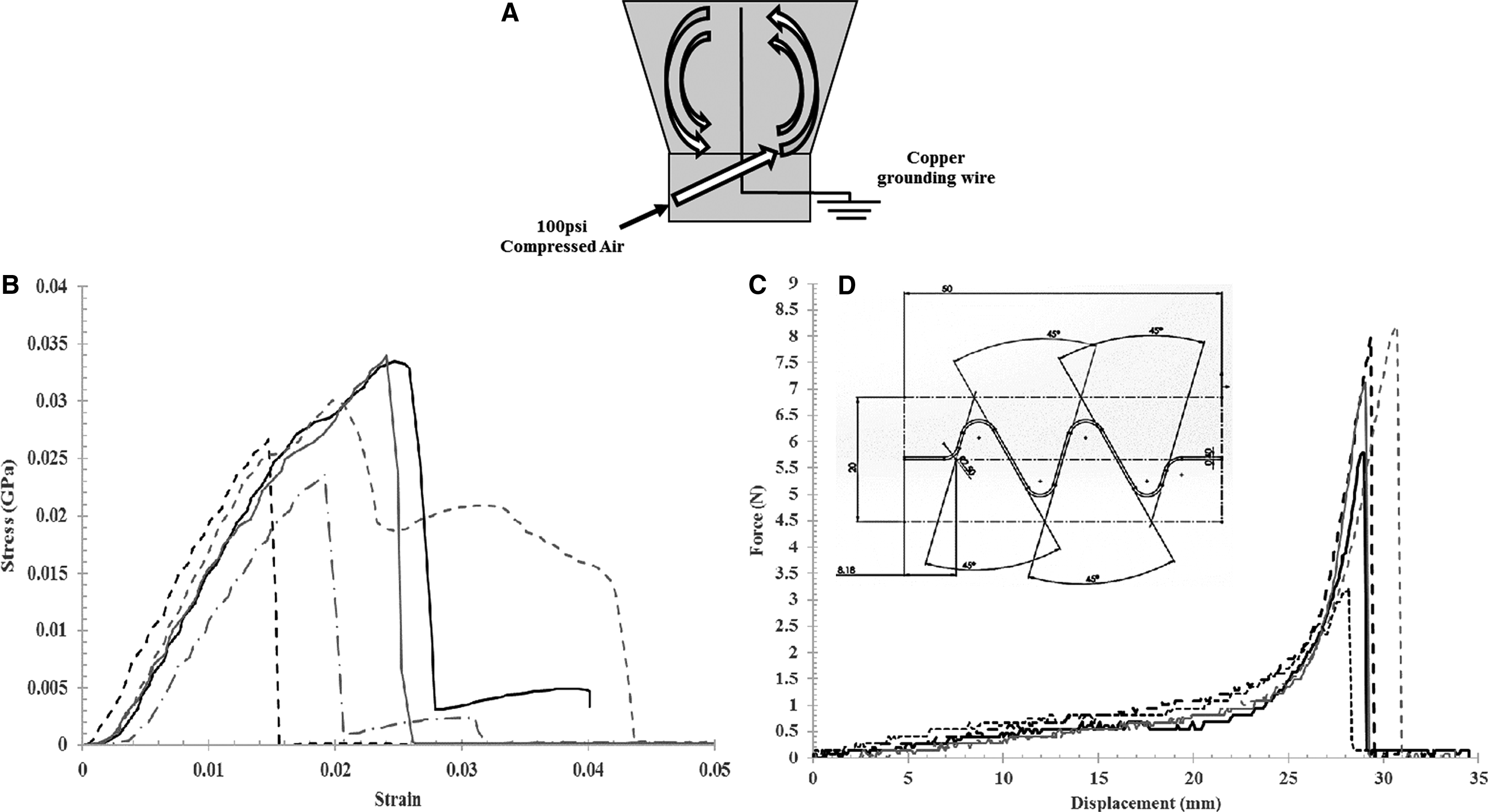
All actuators were designed on SOLIDWORKS 3D-CAD and FFF on a MakerGear M2 with Simplify3D software. Actuators had a cross section of 1.5 × 0.4 mm, overall length and width of 50.0 and 12.38 mm, respectively, and were printed with a 0.35 mm diameter nozzle at 240.0°C with the bed at 70.0°C (Fig. 1D). Software was coded to print with an extrusion multiple of 0.97, extrusion width of 0.39 mm, layer height of 0.3 mm, and a printing speed of 600.0 mm/min.
Physical and chemical properties of material were acquired with the use of Fourier transform infrared spectroscopy (FTIR), differential scanning calorimetry (DSC), scanning electron microscope (SEM), and tensile testing. SEM images were taken in sections at the ends and middle cross sections of the actuator. Sections were made by freezing the samples at −10°C and cutting with a razor blade at 90° and 45°. An MTS Model Sintech 1/S tensile machine was used for tensile testing (maximum load cell capability of 900 lbs/408 kg), wherein actuator force data were collected with an iWorx data logger, 250 g force transducer, and a 100°C k-type thermocouple transducer to monitor force and temperature simultaneously.
To deform the actuators/samples, a water bath of 70.0°C was used to strain each sample to the varying predetermined strain values; strain values include 100%, 80%, 60%, 40%, and 20%. The water bath provided a constant temperature reservoir along with fast shape fixing and recovery setting times.
The predetermined strain values were to demonstrate the range of recovery force with varying strain inputs, whereas 70°C was used since the Tg of PLA is 60–65°C. In addition, the samples were cyclically fatigued by stretching and recovering its shape at 70.0°C for each strain value for five cycles. This process was also used to measure the strain recovery of each fatigue cycle at each strain percentage. A common initial fatigue range for SMPs is 5–10 since SMPs in research show a constant shape recovery (SR) after 5–10 cycles.
To ensure that each sample was at room temperature before being stretched, the samples would be submerged in the water bath, stretched, and then allowed to cool at 21.0°C for 5 min before testing. For fatigue cycles greater than one, the process is repeated until the number of fatigue cycles is reached.
Force data were collected by placing the samples in an incubator with a temperature ramp rate of 1.12°C/min to accurately show the onset and end of the contraction cycle; incubator was heated from 30°C to 70°C ± 5°C. In addition, a faster heating source was created with ceramic heating elements to demonstrate the actuator force characteristics under a temperature ramp rate of 8.68°C/min, approximately eight times faster. The ceramic heating system was placed inside of the incubator, where the incubator was heated up to 40°C to get the entire chamber at 40°C and then the ceramic heating elements were activated to reach a temperature of 75°C. Two 40.0 mm diameter circular ceramic heating elements, with an internal resistance of 4.8 Ω, were used with an applied 9.0 V and 1.015 A to generate radiant heat.
Results
Material characterization
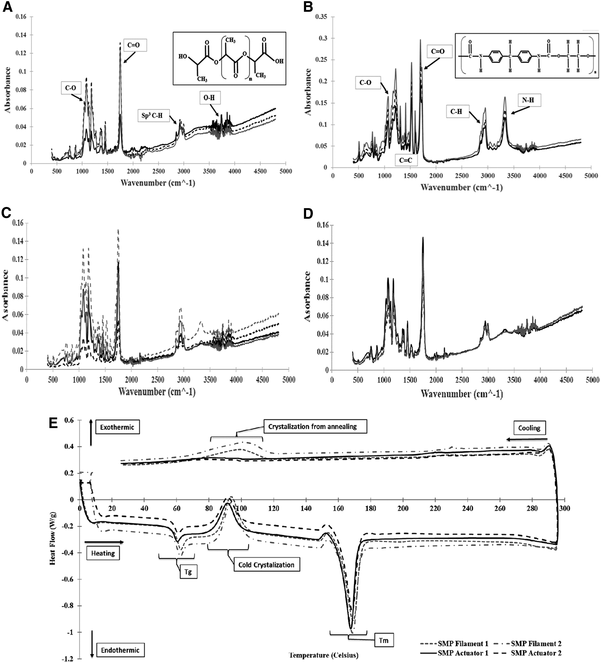
Once the SMP filament was extruded, it was tested with an FTIR machine to identify that both PLA and TPU were present in the melt mixed blend. FTIR of PLA, TPU, and SMP filament was tested with three samples with sweeps from 4800 to 400 cm−1. In addition, the FFF printed actuator was tested with three samples to show that the extruded device still had a blended polymer matrix (Fig. 2A–D). FTIR results show that all key bonds are present in all samples and types.
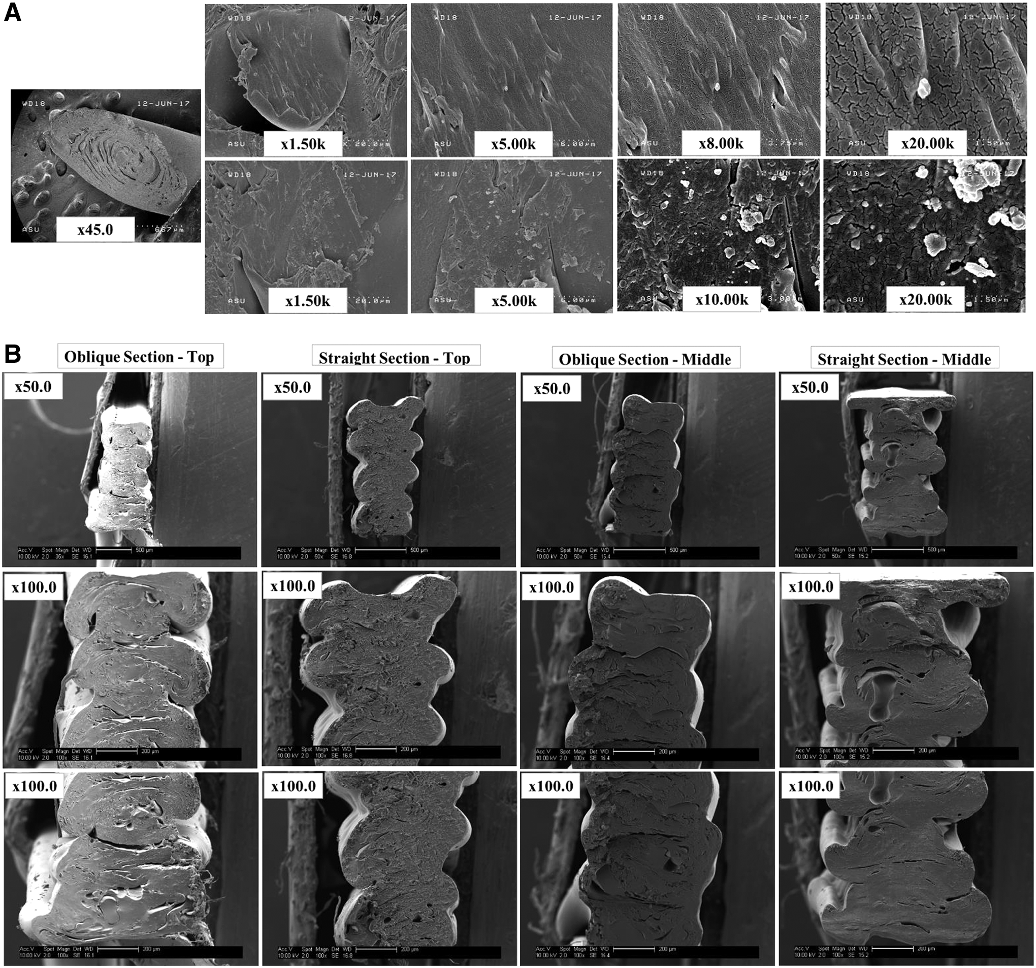
After FTIR testing, the extruded SMP filament was evaluated with an SEM to view the distribution of TPU within the PLA matrix (Fig. 3A). Imaging was taken with an oblique cut, ∼45°, through the filament and imaged from 1500 × to 20,000 × magnification. Images showed that the distribution of TPU within the matrix is evenly apart from one area where the TPU appears to be in clusters instead of blended.
SMP filament was tensile tested to find its mechanical property at a loading rate of 50 mm/min, following ASTM D638 standard. Five samples were tested under tension and showed that the SMP filament is brittle, due to the 70% PLA matrix content. Testing showed a consistent linear elastic region with fluctuations in peak stress ranging from 0.0337 to 0.0236 GPa (Fig. 1B). Fluctuations in peak force appear to be due to TPU clusters seen in SEM imaging.
FFF actuator characterization
To determine the SR percentage at each strain and fatigue cycle, the samples were stretched at 70°C. Results after five cycles show that 100% strain has the lowest SR of only 24.6%, 80–60% strain has similar SRs of 31–29.2%, and 40–20% strain has the highest SR of 43.2–42.6% (Fig. 4A–F). It is observed that using strain values of 100–80% results in actuator material fracture/peeling due to the increased induced stress with fatiguing. The ideal strain is 60% due to the high SR similar to that of 20% for typical mammalian skeletal muscle strain,22–27 and positive material fatigue results, whereas 40% and 20% strain generate no stress recovery.
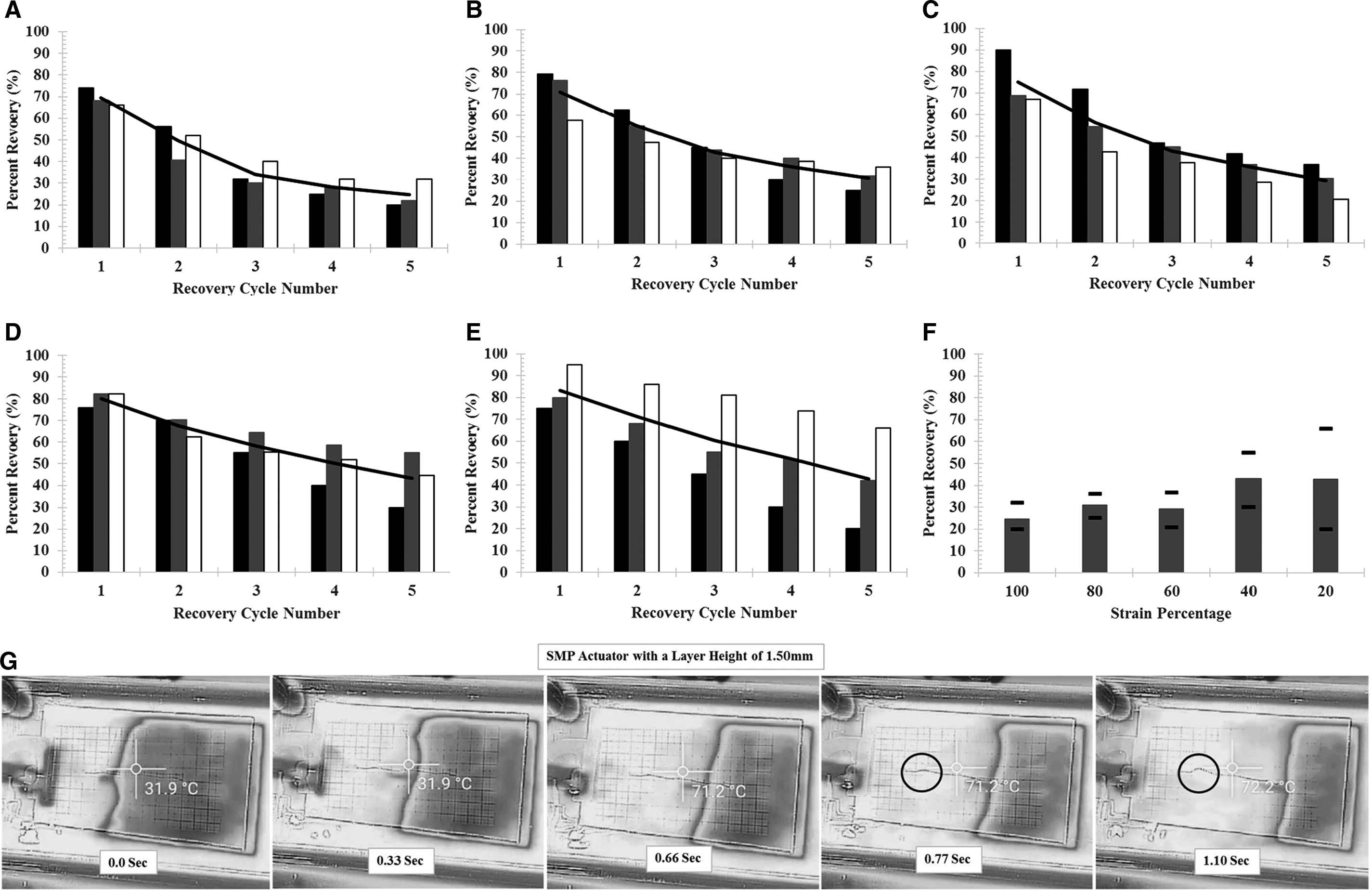
The response time was also determined since the true actuator response time cannot be established due to the force testing system. Response time was determined with an FTIR one thermal imaging camera (frame rate of 0.11 s) and 70°C water bath (Fig. 4G). The actuators were attached at one end on the platform, allowing the other end to be free to move/actuate, and were submerged in the water bath at a low inclined angle, 10–15°. This allows for the actuator response to be measured without a rush of water that would generate high turbulence if the platform was submerged parallel to the water.
The imaging showed that the actuator with a thickness of 1.5 mm had an initial response time of 0.77 s. In addition, actuators with thicknesses of 1.2 and 0.9 mm had response times of 0.77 and 0.66 s, respectively. The thinner samples were not tested for contractile forces since they would not generate enough force for the force transducer and were difficult to remove from the bed without damage, but show that a thinner sample would have an increase in response time.
For actuator force testing, the actuators were tested similar to an isometric muscle contraction, wherein the FFF actuator is stretched to a given strain percentage, fixed at the bottom and to the force transducer, and then heated to 70°C. Isometric test setup was used since it allowed the maximum stress generated at each strain to be evaluated and allowed for a force transducer to be employed. If the actuator was allowed to displace during contractile testing, the actuator would have to lift various masses and the generation of stress could not have been recorded.
Strain values used show the range of capable displacement values for the actuator since straining >100% causes fracture in the actuator during stretching. The strain values of 100%, 80%, 60%, 40%, and 20% represent displacement values of 50, 40, 30, 20, and 10 mm, respectfully.
From the results (Fig. 5A–I), the samples with 100% strain cycled one to five times showed the largest peak force along with the greatest rate/slope of force generation, wherein the force and rate decreased linearly as the strain percentage decreased until 40% and 20% when the actuator could not generate enough internal stress to cause a recovery stress/force. The peak contraction values for each strain are comparable to mammalian skeletal muscle contraction values and follow a nonlinear force generation due to the spring shape design and force generation throughout the entire Tg zone.
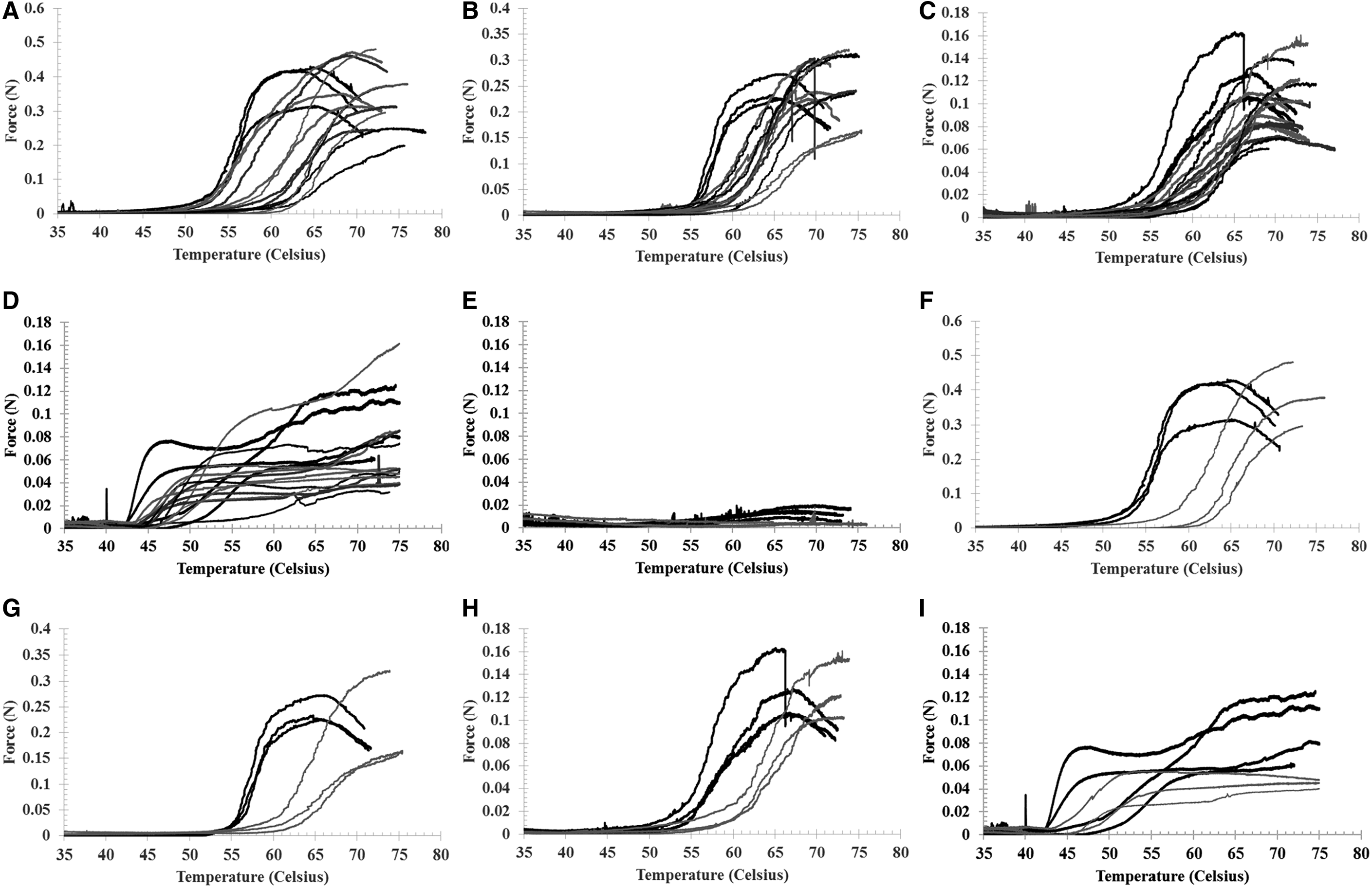
Mammalian contractile force values range from 0.1 MPa (typical/average) to 0.45 MPa (maximum), and the actuator here ranges from 0.58 to 0.17 MPa for 100–60% strain, respectively. It is observed that after cycling the actuator once, there is an initial drop in peak force and rate averages, followed by a relative leveling or constant peak force and rate. In addition, we see that the 60% strain samples tested in the ceramic heating system show results comparable with those of its counterparts tested in the incubator chamber. This demonstrates that increasing the heating rate will not affect the performance of the actuator. Sixty percent strain was chosen since it showed the highest strain recovery with minimal material failure.
To determine the nonlinear passive tension characteristics of the actuator, five samples were tested under tension at 50 mm/min. The results show that as the actuator is displaced, there is a shallow force uptake followed by a steep absorption of force and then failure at 30 mm of displacement, which follows the nonlinear passive tension that skeletal muscles demonstrate22–27 (Fig. 1C).
Analysis for FFF variances
To determine the quality of the actuator and whether there is any thermal degradation of the SMP after FFF, SEM imaging and DSC testing were performed. DSC results (Fig. 2E) show that there is a decrease in the amount of thermal energy required to progress through each material phase when the filament is fused filament fabricated. The Tg and melting temperatures (Tm) are similar, but the decrease in heat flow/specific thermal energy demonstrates that there is less energy needed to go from one state to the next due to thermal degradation. Furthermore, there is spike in exothermic energy during annealing of the filament that is not seen in the FFF actuator.
SEM images (Fig. 3B) show that there is inconsistency in the density/layer adhesion throughout the FFF actuator. Imaging shows parting lines where the printed layer has not fully or partially fused with the layer beneath it, and that the cross section is not uniform with valleys and peaks present. This surface effect is also shown in Supplementary Figure S1 (Supplementary Data are available online at www.liebertpub.com/3dp), where a macroscopic view of the actuator's surface is displayed.
Discussion
Material characterization
Initial FTIR and tensile material analysis showed that the extruded SMP filament and FFF actuator had the appropriate carbon (C), hydrogen (H), oxygen (O), nitrogen (N), Sp 3 carbon to hydrogen, and carbon to carbon or oxygen double bonds for PLA and TPU (Fig. 2A–D). The FTIR results show the amount of infrared radiation (IR) absorbed versus wavenumber. This is obtained since absorbed IR causes a molecule to be excited into a higher vibrational state, where the change in energy from the at-rest to excited molecule state is a function of the amount of absorption at a wavenumber by a particular molecule/bond. 30
FTIR testing was followed with SEM imaging to evaluate the distribution of TPU within the PLA matrix since PLA makes up 70% of the blend. In Figure 3A, the samples were coated with a gold/palladium film to remove charge from the surface during imaging. The dark regions/area make up PLA where the lighter or white highlights/regions are TPU. There is even distribution of the TPU within the matrix, with possible regions of TPU clustering. Imaging shows possible clustering within the matrix since the TPU particles are spherical/isolated instead of elongated and distributed. The clustering effect could have been caused by using a single-screw extruder with a premixed pellet blend, where a twin-screw extruder with simultaneous blending could resolve the particle isolation issue. This clustering effect appears to have influenced the tensile peak results of the SMP filament.
The tensile results show linear elastic regions with fluctuations in peak stress. These fluctuations may have been caused by clustering, where a large cluster may cause a high stress or weakening point in the sample and cause it to fail early. In addition, two samples showed a slight increase in ductility with one sample having a secondary peak. The increase in ductility and the secondary peak are due to a particle or cluster of TPU material within the cross section. Even though SEM imaging showed an evenly distributed composite, if the point of failure in the filament has a cluster of TPU, the sample can demonstrate a secondary tensile peak. The increase in ductility is minimal in these samples and does not affect the elastic tension regions. The actuator only works within the elastic region of the polymer since going above the elastic region would cause plastic deformation in the actuator.
FFF actuator characterization
The functionality of the actuator was demonstrated with contractile, SR, and passive actuator tensile testing at a loading rate of 50 mm/min. SR, along with initial response time, shows that the actuator with 60% strain is optimal for SR with a response time of 0.77 s (Fig. 4). Since cyclic fatiguing appears to level off after five cycles for all strains, 60% strain is ideal since it achieves 29.2% recovery with minimal plastic deformation.
Strains of 80% and 100% exhibit higher peak force and higher response rates, but due to the increased applied stress, they have lower SR due to plastic deformation/breakage. Since the actuator has an overall length of 50 with 78 mm in material length, when the material is strained well past 78 mm, it begins to fail. The 60% strain is only displaced to 80 mm, which results in minimal applied strain (2.0 mm) after full stretch while still generating internal stress. This allows the actuator to stay within the elastic region of the composite, shown in Figure 1B.
The spring shape design allows the actuator to have a high deformation before change in cross section (CS) and high SR response initially due to the decrease in CS (high stress on polymer chain structure) followed by a lower response once the CS is recovered (low stress on polymer chain structure). A straight line/wire would only allow for deformation of the polymer with a decrease in CS, which would cause plastic deformation at low strain levels due to the brittle nature of the polymer and decrease in SR. This affect is seen where the 100–80% strain samples have a low SR due to plastic deformation and the 60–20% samples have a high SR due to no plastic deformation (Supplementary Fig. S2).
Results (Fig. 5J–M) from the force/contractile testing showed that as the strain percentage decreases, the peak force and rate (stress/°C) decrease as a linear function. This linear decrease is due to the function of input/applied stress generated during stretching and the amount of stretching/displacement. As the strain decreases, the applied stress decreases since there is less elongation along its cross section. Therefore, when using strains of 40% and 20%, there is no elongation/decrease in the cross section after stretching. This is observed since the strain values higher than 40% show consistent force generation, whereas 40% and 20% show little to zero force generation.
Fatigue cycling the samples showed an initial decrease in peak force and rate (Fig. 5J–M) after one cycle followed by a relatively constant peak force and rate. The onset of force generation is shifted with each cycle, with the largest offset happening after the first cycle. In addition, the force generation follows a nonlinear pattern of contractile force due to the gradient response to thermal input and SR, and actuator spring shape. The SMP responds nonlinearly since force generation is initiated before the Tg, near 50°C, and continues through the Tg range, near 75°C, along with the spring shape, allowing a duel SR effect already described.
Lastly, the FFF actuator was tested under tension to demonstrate the passive tension properties of the design (Fig. 1C). As the actuator is displaced, it provides minimal resistance initially, and then has an exponential increase in resistance to displacement when nearing the complete straightening of the actuator. This spring design allows for the actuator to have nonlinear properties and behave comparably with skeletal muscle in passive movement, strain/SR, and peak force generation.22–27
Limitations to the SMPC actuator
The main limitation for this actuator acting as a biomimicking skeletal muscle prosthetic actuator is that the response time needs to be reduced by approximately 0.5–0.6 s, resulting in a response time of 0.17–0.27 s. The response time for peak force generation from an action potential for skeletal muscles ranges from 100 to 200 ms for type I (slow twitch) and 20–60 ms for type IIA/B (fast twitch) skeletal muscles.
As previously stated, the actuator with a thickness of 0.9 mm had a response time of 0.66 s compared with the 0.77 s with a 1.5 or 1.2 mm thick actuator. Therefore, to overcome the response time limitation, the actuator thickness will need to be scaled down for future testing to achieve the faster response time. In addition, higher sensitivity and lower force detection strain gauge sensors will need to be employed to detect the lower SMPC actuator force.
When using the current response times, 0.77–0.66 s, they more closely represent a large bundle of muscle fibers contracting to achieve peak force generation. The current response times still allow for a fast-acting actuator, but in their current state would be better suited for long, constant, and controlled contractions instead of fast acting movements in a prosthetic. For example, lifting heavier objects where controlled movements are necessary would be better suited for the SMPC actuator in its current state.
Analysis for FFF variances
To determine the reasoning for variances in contractile data, DSC was used to determine polymer degradation and SEM to evaluate layer adhesion, and print quality of the actuator. The DSC test was heated from 0°C to 300°C and then cooled to 22°C at a rate of 10°/min. The results (Fig. 2E) first show a Tg endothermic event, followed by a cold crystallization exothermic event, then the Tm endothermic event. Upon cooling from 300°C, an exothermic event is seen due to crystallization from annealing. An endothermic event represents an absorption of heat into the sample and an exothermic event represents the release of heat from the sample.31–36
The cold crystallization event is present since the SMP's content is 70% PLA, which is an amorphous semicrystalline polymer. The TPU has a pseudo crystal structure wherein the hard segments within the polymer are ordered and the soft segments are amorphous. Once the SMP reaches its Tg, the polymer chains reorder themselves and increase their crystallization, inducing an exothermic event. If the polymer had high crystallinity originally, then the exothermic event would be minimal or not present.
When comparing the DSC cycles from the SMP filament with FFF actuator, it is visible that thermal degradation is present due to the decrease in specific thermal energy (area under the curve) in each endothermic phase along with the absence of an exothermic event during the transition into the Tg when annealing from 300°C. Thermal degradation is caused by oxidation and random chain scission due to thermal cycling, which decreases the molecular weight.
Lastly, SEM imaging revealed that the FFF actuator has an inconsistent cross-sectional area (CSA) and layer separation (Fig. 3B). Images were taken at the ends and center of the actuator and revealed that the layer adhesion is inconsistent throughout the actuator and causes layer separation. Separation is caused by the cooling of the layer beneath it before the next layer is extruded on it and these are displayed as parting lines or gaps in the image. In addition, the CS of the actuator is composed of peaks and valleys instead of constant/straight lines, which causes a variation of the CSA throughout the sample.
Conclusion
We present here a biomimicking FFF skeletal muscle actuator that demonstrates nonlinear properties, peak force, and strain comparable with those of mammalian skeletal muscle, and has response time of 0.77 s, low operating temperature at 70°C, and has a low mass (74.0 mg), volume (46.74 mm3), and material costs of $0.0098 per actuator.
The FFF actuator here has nonlinear contractile properties that have peak contractions similar to mammalian muscles ranging from 0.58 to 0.17 MPa for 100–60% strain, respectively. In addition, the ideal strain of 60% has a strain recovery of 29.2%, which is comparable with the 20% for typical mammalian skeletal muscle strain.
Future directions are to improve the actuator's durability and loading protection within a prosthetic. Durability will be improved by reducing the variation in data by eliminating the use of PLA and TPU pellets that have already been extruded before melt blending and FFF printing them to reduce thermal degradation, and to increase layer adhesion by elevating the existing FFF layer temperature before the next extruded layer.
The actuator's durability will be evaluated after modifications are made, using fatigue life-cycle testing. This will allow for the durability and failure mechanics of the polymer actuator to be assessed. By making the modifications before fatigue life-cycle testing, the failure mechanics from solely cyclic fatigue can be studied.
Lastly, the SMPC actuator will be protected from overloading with the use of pressure/shear sensors, mechanical stops, and/or mechanical failure releases. Since the actuator relies on SR and stress generation within its Tg, if it were to lift an object over its maximum contractile stress, it could cause a change in its fixed/memorized shape and, therefore, changing its contractile properties.
The pressure/shear sensor feedback system would allow the user to detect whether an object is too heavy for the actuator(s) to lift. The mechanical stops would prevent any excess rotation in the opposite direction of the intended contractile direction due to overloading. The mechanical failure release would be composed of an arm and inclined angle. This would allow the actuator to contract until it reaches its maximum stress, and if a greater stress is seen, the arm would release and deactivate the actuator. The arm is attached to the actuator and is only able to slide or pivot along the inclined angle with enough input stress.
Footnotes
Author Disclosure Statement
No competing financial interests exist.
References
Supplementary Material
Please find the following supplemental material available below.
For Open Access articles published under a Creative Commons License, all supplemental material carries the same license as the article it is associated with.
For non-Open Access articles published, all supplemental material carries a non-exclusive license, and permission requests for re-use of supplemental material or any part of supplemental material shall be sent directly to the copyright owner as specified in the copyright notice associated with the article.
