




Abstract
Abstract
Three-dimensionally (3D) printed scaffolds and cell culture lattices with microscale features are increasingly being used in tissue engineering and regenerative medicine. One additive manufacturing technology used to design and fabricate such structures is melt electrowriting (MEW), a process which needs to be scaled in production to effectively translate to industrial applications. In this study, a scale-up printer, designed with eight simultaneously extruding heads, is constructed and validated. Importantly, identical structures could be fabricated using parameters developed from a single-head system, therefore establishing a MEW printer ecosystem that allows for direct upscaling from laboratory research. The successful transfer to vertically mounted collectors produced homogeneous reproducible scaffolds with identical morphologies and fiber diameters. These proof-of-concept experiments also show that MEW is capable of large-scale fabrication, successfully demonstrated by manufacturing 780 × 780-mm sheets of scaffolds/lattices. This study demonstrates that upscaling MEW can be realized by multiplying the number of print heads, while vertical mounting of the collector significantly reduces the MEW footprint. Additionally, economic aspects were considered during the development and costly components, such as the x, y, and z linear axes, were minimized. Herein, a systems engineering approach for the development of a high-throughput MEW technology platform is presented for the first time.
Introduction
The recent adoption of additive manufacturing (AM) technologies within the fields of tissue engineering and regenerative medicine (TE&RM) has greatly expanded the design potential and fabrication perspective of various medical products.1–3 These include patient-specific implants and medical devices, 4 lab-on-chip technologies,5,6 physical models, 7 and three-dimensional (3D) scaffolds for cell culture, 8 here termed lattices. 9 Such a diverse range of applications belies a thriving sector of additive biomanufacturing (ABM) technologies for the 21st century's medical industry.1,10,11 In the classical TE&RM approach, cell seeding and reimplantation defined the design and fabrication of 3D structures known as scaffolds. 12 Ideally, such ABM platforms should be capable of creating 3D architectures with a highly porous interconnected network that guides tissue growth and remodeling. 8 Since traditional fabrication techniques for scaffolds, such as solvent casting, freeze-drying, porogen leaching, fiber bonding, dual-phase separation, and gas foaming, 13 only allow limited control over the final geometry and porosity, various research efforts have been applied to AM techniques. These are, for example, stereolithography, selective laser sintering, and fused deposition modeling (FDM), approaches that enable direct material deposition to further increase design freedom and control over scaffold architecture.1,14 Dissolvable structures, termed fugitive inks, have expanded the volume of the construct made through improved nutrition to cells.15–17
Separate from ABM, the TE&RM community also embraced electrospinning technologies 18 to generate structures from polymer fibers in the micron to submicron scale to significantly increase the surface area available to cells. The generation of an electrical field around an extruded viscous fluid leads to ejection of a charged jet that is collected on a grounded or oppositely charged collector. 19 Most commonly, sufficient viscosity for generating a continuously charged jet can be achieved by dissolving the polymer in a solution. 20 During its flight phase, the charge density along the jet increases, 21 which significantly distorts the straight flight path of the traveling fiber, causing buckling of the jet 22 and resulting in scaffolds with highly randomized architectures. 23 On the one hand, electrospinning, compared with other polymer fabrication technologies, enables high mass flow and hence greater material throughput; on the other hand, it is challenging to accurately place the fibers. It is worth noting that a considerable amount of solvent is lost in this process, typically 80–90%, but sometimes it is greater. 13 From an engineering perspective, the low manufacturing rates facilitated the design of scale-up electrospinning machines with multiple nozzles. 24 These can be aligned in close proximity as interference of electrical field lines does not significantly affect placement accuracy. Hence, this lack of ability to accurately deposit fibers significantly decreases the complexity of the machine design and permits the technology transfer to industrial applications for high throughput. From an industrial perspective, the simplicity and comparatively large production rates of solution electrospun scaffolds with nonwoven structures paved the way toward commercialization. 25
The principles of electrostatically generating fibers from fluids can be similarly realized with molten polymers, referred to as melt electrospinning. Compared with solution electrospinning (SES), which is characterized by random deposition of fibers, the abundance of solvents in the melt electrospinning process increases the viscosity of the polymer and reduces the charge component of the electrified jet, in turn stabilizing the flight path of the fiber for more precise deposition on a collector. 26 The integration of a computer-controlled translational collector for melt electrospinning, similar to conventional FDM technologies, results in a hybrid approach, termed melt electrowriting (MEW), which can 3D print micron-sized fibers in a highly controlled mode. Using direct-writing principles, MEW produced scaffolds with porosities greater than 95% and fiber diameters in the lower micron 27 to submicron scale. 28 As an ABM technology, MEW has potential to manufacture highly porous and well-organized scaffolds using biocompatible degradable polymers.9,29,30 Such ABM products can also be used temporarily for in vitro expansion, demonstrated by the application of MEW lattices as an alternative to beads for regulatory T (Treg) cell expansion, with potential for clinical translation. 9 However, while there has been work on scaling MEW,26,31 there is no concept described in the current literature that outlines how MEW scaffolds and cell culture lattices can be scaled to a higher production rate. To successfully translate such promising applications for MEW within the TE&RM community, achieving the economies of scale is an essential next step for translation of technology.
Similar to other AM technologies, such as FDM, physical properties of a molten polymer typically limit the extrusion speed of the material through the needle during MEW; however, accurate deposition results. Conversely, material throughput (mtp) per time for SES is comparably low due to the specifically small extruded volumes; yet, these scaffolds provide significantly increased surface areas. As a manufacturing technology, MEW retains more material through processing than SES; however, it requires significantly lower extrusion speed rates compared with FDM. 32 Therefore, existing MEW printers are associated with lengthy fabrication times and fail to achieve 3D printed structures with high surface-to-volume ratio (svr) per amount of extruded material (svr/mtp) in manufacturing time frames. This adversely affects the economies of scale in comparison with other conventional production technologies. 33
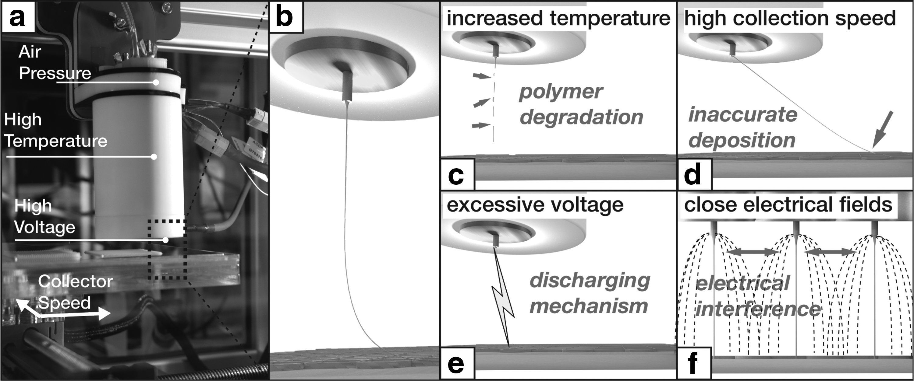
To reduce the manufacturing time of MEW scaffolds, there are some general aspects to consider (Fig. 1). Elevated printing temperatures accelerate degradation of the polymer and in turn generate more electrically charged degradation products. 34 Moreover, shear-thinning polymers with rapid solidification are essential for extrusion-based printing. 35 Low-viscosity polymers are difficult to fabricate with good shape fidelity and high resolution. A different strategy to reduce MEW printing times is to increase the collection speed, although this leads to inaccurate fiber placement. There are limits in higher voltage application due to corona discharge, that is, sparking at amplified voltages under respectively small distances. 36 Finally, different multi-nozzle systems have been proposed for MEW37–40 ; however, these concepts (Fig. 1d) do not allow the manufacture of reproducibly accurate scaffold architectures, yet produce randomized morphologies. Existing alternatives comprise print heads extruding multiple fibers, either distributed in a two-dimensional plane assembly 38 or circularly aligned on one print head. 31 Nozzle-free melt electrospinning has demonstrated that 60 individual linear jets can be generated with a single head, yet without positional control. 31 Manufacturing throughput is significantly improved with this approach; however, applying this as a direct-writing technology will affect resolution and/or well-ordered microscale architectures (Fig. 2). In summary, and in an approach pursued here, a multihead strategy is likely to be an essential component for MEW scale-up and this approach is pursued in this study.
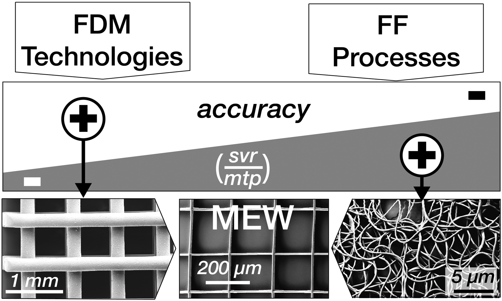
(Top) Schematic comparison of MEW's technological predecessors (fused deposition modeling, MEW, and fiber forming). (Middle and Bottom) Illustration of the conceptual combination of accuracy and the desired high svr of the scaffold per mtp. svr, surface per volume ratio; mtp, material throughput.
Recently described high-throughput concepts for AM in general can be categorized into two classes: (1) multiple nozzles integrated into one print head and (2) multiple individually moving print heads. Hansen et al. 41 demonstrated the capacity of multi-nozzle arrays—described as a hierarchical branching network—within one print head to fabricate multilayered architectures, resulting in a highly flexible and scalable concept for extrusion-based deposition. In contrast, Project Escher, introduced by Autodesk, Inc. (Mill Valley, CA), and commercialized by Titan Robotics, Ltd. (Colorado Springs, CO), validated a 3D printer with multiple independently controllable heads designed to manufacture larger and more complex objects. Another approach to scale up assembly was based on combining parallel 3D printer heads with automatization of the part removal, demonstrated by the Form Cell printer (Formlabs, Inc.) or shown in a concept, called “Figure 4” (3D Systems).
In this study, the successful design and development of a high-throughput HT-MEW printer (Fig. 2) are achieved and validated using medical-grade poly(ɛ-caprolactone) (PCL). The HT-MEW printer simultaneously deposits polymer fibers from eight individual print heads, which allows manufacturing either over thousands of small dimensioned or one large multilayered scaffold/lattice with homogeneous morphologies with fibers in the lower micron scale.
Materials and Methods
HT MEW printer design
The printer consists of an enclosure, extrusion heads, a collecting platform, and external parameter-controlling units, including a PC (high-voltage controller, driver unit for the translational collector, and temperature controller box). A systematic design overview is shown in Figure 3 and rationalized in more detail in the following sections.

Parameter-controlling units
The in-house-designed temperature controller box regulates the temperature of the eight print heads, each individually equipped with two heating elements; a detailed design that can also be found here. 27 All print heads are regulated by temperature controllers (N1030-PR-24V PID Temperature Controller; NOVUS, Australia) and switched by relays (SSR-120; Conch), while power is provided by an 8-kW power supply (RSP-750-12; Mean Well, Taiwan). Pressure is regulated by two commercially available regulators (electro-pneumatic regulator; SMC Pneumatics Pty. Ltd., Australia) that receive, as input, air pressure from a standard laboratory pressure line to distribute air equally to the individual heads.
The electrostatic field between the head and the collector is established through a high-voltage power supply unit (D-ES40PN-5E/DC; Gamma, High Voltage Research). In-house-designed splitters consist of Perspex boxes filled with highly insulating resin (EL171C/566 Polyurethane; Robnor, England), which distribute the voltage through appropriately insulating cables (HS 30 PTFE; GES GmbH, Germany). A computer is used to transfer motion signals to the in-house-designed motion control box, which consists of a power supply unit (SP-320-48; Mean Well, Taiwan) and three drivers (ND556; Leadshine) individually controlling each of the three axes by communication through a parallel port interface (KTA-205; Ocean Controls, Australia). The previously mentioned hardware drives the instrument parameters (Fig. 3), excluding the collector distance, which is adjusted manually.
Printing enclosure
The printing enclosure consists of two vertically aligned stages mounted to a frame, a horizontally fixed stage, and the print heads, pointing toward a vertically mounted collector (Fig. 3). On each side of the collector, the four print heads are equidistantly mounted on a custom-made laser cut Perspex construction. Both head assemblies are connected to vertically aligned linear stages (XN10-0030-E01-71; VELMEX) and powered with a stepper motor (FL57STH51-2804A; Ocean Controls). The horizontal axis, a linear stage (MN10-0300-E02-21; VELMEX), is driven by the same standard stepper motor as mentioned above and moves the in-house-designed collecting platform. 9 The latter consists of two aluminum plates of 3 mm mounted on each side of the Perspex frame, which provides stability. Both plates are electrically grounded through a wire and additionally insulated with two layers of insulating tape (KPT-4 KAPTON; DuPont), which is between the aluminum and the Perspex. This design solution aims at preventing electrical interference between two oppositely located charged heads and was verified by a simulation conducted with COMSOL Multiphysics® Simulation software (Version 5.2; COMSOL, Inc.). The results reveal no electrical interference between individual heads at maximum voltage and closest applied distance (additional information is provided in the Supplementary Fig. S1). The upper end of the collecting platform is attached to two linear stages (TW-01-20, drylin® T Linear Guides), facilitating stable and frictionless movement.
Both vertically aligned slides are fixed to a supporting frame, which is made from precut, extruded aluminum profiles (ITEM; Modular Component and Automation, Australia). To avoid potential vibration, the structure is bolted to two custom-made metal plates (aluminum, Kilner's Engineering, Australia) that are connected to a heavy-duty workbench (OZ Storage Solutions, Australia).
The custom-made enclosure had three doors (ITEM; Modular Component and Automation) to provide access to the collector and printing heads. Operational safety is guaranteed by separately configured magnetic interlocks (XCSDMP5902; Telemecanique Sensors, France), which interrupt the high-voltage supply to the heads when opening during operation. The HT-MEW printer is grounded through the common earth of the laboratory power socket.
Instrument parameter control
The movement of all three stages is controlled by the MACH3 software (MACH 3, ARTSOFT; Newfangled Solutions LLC), which accepts individually written G-codes to fabricate lattices. The distance between the heads was designed in accordance with dimensions of the collector, which allows overlapping structures of the printable areas of each individual head. The syringes (EFD Barrel O.3 mL clear 50; Nordson Australia Pty. Ltd.) were filled with 3 mL of medical-grade PCL (Purasorb PC 12; Purac Biomaterials, The Netherlands) and inserted into the print head.
One innovative feature of this HT-MEW printer is its vertical collector configuration. Due to the small amount of extruded melt, the electrostatic force predominates gravity, which allows accurate MEW from the side. In turn, this vertical mounting allows both sides of the collector to be directly written upon. To commence MEW, the heads are driven to the starting position, shown on the left side of Figure 3b. After completion of the printing process, the scaffolds can be collected by detaching the collecting platform from the horizontal slide and removing it through the front door (Supplementary Fig. S2).
Assessment and characterization of high-throughput print quality
If the diameter and fiber spacing of scaffolds printed with a research-level, single-head MEW device in a horizontal mode 27 can be replicated by a vertically mounted multi-nozzle system, then an MEW printer technology platform can be developed. Second, the reproducibility of MEW lattice manufacturing was characterized by analyzing 32 of the 1152 scaffolds printed with eight different heads on both sides of the collector. Finally, the capability of printing large-scale scaffolds was demonstrated by manufacturing lattices with dimensions of 780 × 780 mm.
Feasible parameter settings, which lead to stable printing conditions and have been identified in previous studies,27,42 were applied to the HT-MEW device. The quality of the electrostatically generated fiber and its deposition on the collector relies on a well-balanced interplay of the most prevailing instrument parameters. This means that the total of all forces acting on the fiber arising from mechanical drag forces (collector speed) or electrostatic forces (applied voltage) in the respective combination with viscosity (applied temperature) and mass flow (applied pressure) must be adjusted accordingly to generate a stable fiber. Therefore, the following instrument parameters were used for print quality assessment and characterization of the high-throughput electrowriting capabilities of the HT-MEW printer (P_1, P_2, and P_3, Table 1).
Instrument Parameter Settings and Their Units for Three Different Printing Experiments P_1, P_2, and P_3, Which Individually Have Different Numbers of Layers and Pore Sizes
Once the MEW scaffolds were printed, images were taken with a digital single-lens camera (D90; Nikon), an inverted benchtop light microscope (Eclipse Ts2R; Nikon), and a scanning electron microscope (TM3000; Hitachi, Japan). Micrographs obtained with the inverted benchtop light microscope were used for the characterization of fiber diameter and fiber spacing using ImageJ (Version 1.51q; National Institutes of Health). Evaluation of results (*p < 0.05) was conducted using statistical software (PRISM 7; GraphPad Prism 7 Software).
Results
Operational functionality of the HT-MEW printer concept
A basic systems engineering approach led to development of a prototype HT-MEW printer (Fig. 4), successfully showing a combination of the fundamental operation principles from conventional AM technologies in regard to deposition accuracy and traditional fiber-forming processes in terms of generating high throughput (Supplementary Video S1). Functionality of the concept was verified by building a prototype, which comprises eight simultaneously operating print heads to direct-write on both sides of a vertically aligned, moving, and grounded collecting platform (Supplementary Video S2). The application of suitable parameter settings (Table 1) enabled MEW from the side as the influence of gravity on the micron-scaled fiber was observed to be negligible in a previously published study. 43 The in-house-developed parameter-controlling boxes facilitated stable polymer extrusion behavior and precise control over fiber placement. The application of instrument parameters was found to be stable for all studied cases.

Images showing CAD models from
Print quality assessment
The performance of the HT-MEW prototype was compared with that of standard, research-level, single-head MEW printers with a horizontally placed collector. 27 The quality of printing was determined by comparing the diameter and fiber spacing of scaffolds using the two configurations. Both fabrication processes were operated under application of the same parameters, as shown in Table 1. Results, as shown in Figure 5, revealed a homogeneous fiber distribution with no significant differences in diameter and fiber spacing between the two printing configurations.

Differences between a standard MEW printer and the HT-MEW counterpart were assessed by analyzing three scaffolds
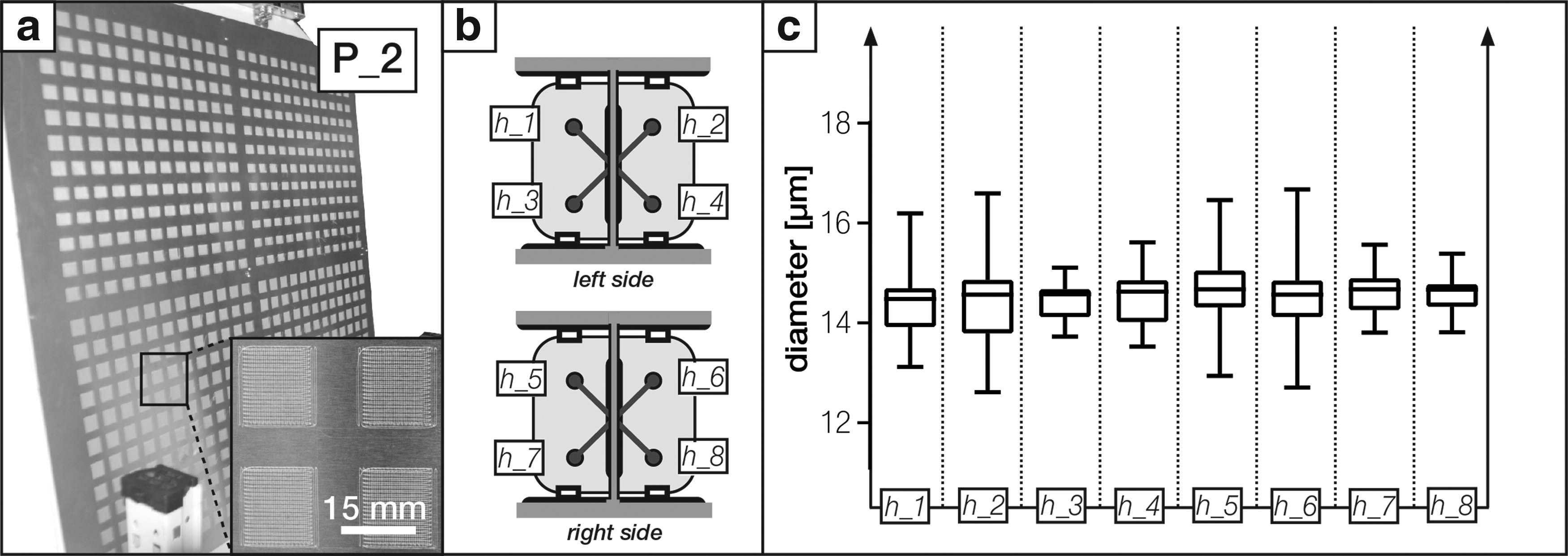
Next, reproducibility of the HT-MEW printer across all print areas of the eight heads was investigated by programming the device to produce multiple equally sized, melt electrospun lattices across different heights at both sides of the collector. Then, the variability of fiber diameter and spacing across different lattices was analyzed. The parameter settings corresponding to P_2 (Table 1) were used that coded the relative movement of the heads to repeatable print squares of 2.25 cm2. The resulting 1152 scaffolds were produced in 87 h, applying a transitional collector speed of 100 mm/min. The results of the analysis of five randomly chosen scaffolds from each print head, shown in Figure 6, revealed overall homogeneity of diameters printed by the eight heads. Interestingly, standard deviations appear to be slightly higher for the heads located at the top rows (h_1, h_2, h_5, and h_6). The inaccuracy within the upper heads could be attributed to the machining of the prototype HT-MEW printer and could be traced back to slight deviations (from true dimensions and angles) of the aluminum frame.
High-throughput printability of large-scale lattices
Once reproducibility of the HT-MEW printer was demonstrated, the capacity of this technology platform to print large-scale scaffolds was investigated by manufacturing lattices with dimensions of 780 × 780 mm and overlapping printing areas between neighboring heads on both collector sides. The large scaffold and its specific areas of overlap are shown in Figure 7. The scanning electron microscope image demonstrates fusion of the overlaying areas, which can be minimized in future work by increasing the distances of the head travel. Lattices with dimensions of 780 × 780 mm were successfully manufactured using the parameter settings from P_2 (Table 1).
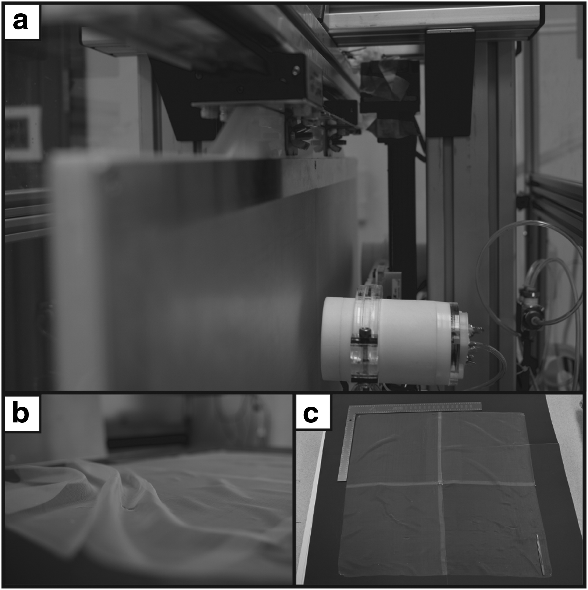
Images of the large-scale scaffold with a size of 780 × 780 mm
Discussion, Limitations, and Future Work
In this study, an original systems engineering concept for scaling-up the process of direct writing molten electrospun polymers to fabricate large-scale scaffolds/lattices is proposed, built, and validated. The multihead prototype demonstrated accurate and repeatable direct writing, with multiple extrusion heads, onto a vertically mounted collector.
Since economics is a fundamental driver for the transfer of new technologies into industrial applications, 44 reduction of expensive components such as the linear stage is essential to be integrated in the machine concept. Vertical mounting of the collector was designed to double the output of MEW scaffolds per printer. Additionally, so-called high-precision x, y, and z stages are significant cost factors in AM machines; yet, a vertically aligned collecting platform requires only one stage, while the platform is guided with a comparably inexpensive slide on top mechanism. Furthermore, from an economic perspective, a vertical machine design minimizes space requirement and hence would decrease costs from a manufacturing area point of view.
Comparable microscale morphologies of all scaffolds were shown with excellent resolution, displaying a machine concept that allows upscaling by using a multihead system and a vertically mounted collector. The fiber always traveled straight toward the collector, driven by high electrostatic forces, and did not visibly get deformed due to gravitational forces, in agreement with the results recently reported elsewhere. 43
Based on the limitations of the processing ability of viscous polymers, the presented design concept successfully shows one path to increase the manufacturing throughput of MEW. For future developments, it can be recommended to alter the number of heads while aiming at a further optimized design, including minimizing the size of print heads. The relative movement of an extruding unit in two directions opens up the possibility to fabricate porous objects with different shapes and volumes. Overlapping designs allow for the manufacturing of large-scaled scaffolds, which can be customized to shapes through laser-cutting techniques. 45 As with all AM technologies, the morphology can be readily altered by controlling the direct-writing path. The HT-MEW printer can also simultaneously manufacture a range of different lattice morphologies that can be studied to improve cell expansion rates or cater for morphological requirements of different cell types. 9
Fiber spacing and diameters were not statistically different between individual print heads. At the top position, errors were found to be larger (Fig. 6c), suggesting that they were caused by the prototyping nature of the device. Nonetheless, the high degree of accuracy and reproducibility of the of scaffolds/lattices of different sizes and architecture are remarkable and present an excellent concept for future translation of the presented prototype MEW technology platform to a truly industrial level.
Future machine design optimizations, aiming at improving throughput while maintaining high print quality, might include the stacking of multiple machine units in line (Supplementary Fig. S3). Additionally, it is possible to further multiply the number of heads to further increase throughput, that is, a combination of scale-out and scale-up.
Conclusion
The presented work describes the first design/scale-up concept of an HT-MEW printer that lays the groundwork to fulfill requirements for industrial applications. The HT-MEW printer design is rooted in using system parameters developed and validated on a single-head MEW research printer with a horizontal design configuration. The systems engineering approach demonstrates how to unlock translational research capacity in an academic environment and how an existing research-level MEW printer concept can be developed into a high-throughput manufacturing platform. The HT-MEW printer technology platform presented has the potential for a myriad of applications in ABM and TE&RM.
Footnotes
Acknowledgments
This research was conducted by the Australian Research Council Industrial Transformation Training Centre in Additive Biomanufacturing (IC160100026) and supported by the Cooperative Research Centre for Cell Therapy Manufacturing (CTMCRC) as well as the Institute for Advanced Study of the Technical University of Munich. The authors acknowledge Pawel Mieszczanek and Ross Kent for their assistance with building the prototype.
Author Disclosure Statement
No competing financial interests exist.

References
Supplementary Material
Please find the following supplemental material available below.
For Open Access articles published under a Creative Commons License, all supplemental material carries the same license as the article it is associated with.
For non-Open Access articles published, all supplemental material carries a non-exclusive license, and permission requests for re-use of supplemental material or any part of supplemental material shall be sent directly to the copyright owner as specified in the copyright notice associated with the article.
