
Abstract
Abstract
By combining various materials that serve mechanical, electrical, chemical, and thermal functions with controlled local distributions, smart devices and machines with multiple functionalities can be fabricated. This article reports a new particle patterning approach during additive manufacturing to fabricate multifunctional smart composite objects. An acoustic field is integrated into the projection-based stereolithography (SL) system to pattern different microparticles into dense parallel curves or networks in the liquid resin. Effects of acoustic field settings and manufacturing process parameters on patterning are modeled and experimentally characterized. Various particle patterning results are presented. An acoustic field-assisted projection SL test bed has been developed. The feasibility of the proposed approach for multifunctional particle–polymer composite fabrication has been verified.
Introduction
M
Compared with traditional manufacturing processes such as machining and molding, multimaterial additive manufacturing technology can enable the full functionality of heterogeneous particle–polymer composites and allow a higher degree of design, by controlling orientations/alignments and local compositions of particles in the polymer matrix. According to the particle manipulation method, multimaterial additive manufacturing processes for fabrication of heterogeneous particle–polymer composites can be classified into two groups: shear flow-induced process and external field-induced process, such as electric field and magnetic field. Compton and Lewis. 5 demonstrated that fillers could be oriented along the printing direction by the shear flow and a lightweight cellular composite was obtained by the direct writing technique. However, such shear-induced process limits the material selection to fibers. Furthermore, due to nozzle clogging issues, only composites with a very limited loading fraction of fibers can be fabricated.
Yang et al. 2 integrated a rotating electric field with projection-based stereolithography (SL) to fabricate bioinspired composites. This process allows a wider choice of materials and works for not only fibers but also for spherical and nonspherical particles. Yet the particle distribution cannot be controlled locally, since the entire printing area was covered by a uniform electric field. Magnetic field-induced processes utilize the magnetic field to control the particle orientation in fabrication of magnetic field-responsive composites 4 and bioinspired composites. 6 Local particle composition control by using a moving magnetic field was also demonstrated.7,8 A major limitation of these external field-assisted processes is that the particles have to be naturally responsive to the applied external field. Otherwise, the particles have to be surface coated with magnetic responsive nanoparticles and maybe still cannot be processed by the manufacturing technique. Pan et al. proposed a method of integrating electrostatic deposition with SL to fabricate particle–polymer composites with locally controlled particle composition. 9 In those work, most methods can either only align or orient particles in the polymer matrix, or only control the local composition. Very few of them are able to simultaneously control the orientation and local composition of particles, thus significantly limiting the domain of the particle–polymer composite that can be explored.
To overcome the material selection limitation and achieve simultaneous control of orientation and composition, this work investigated the use of acoustophoresis in SL process, which is one of the most popular vat photopolymerization-based additive manufacturing processes. Acoustophoresis has the advantages of full particle placement control, no imposed manufacturing constraints, and no material shape or specific physical property requirements.10–15 Utilization of the acoustic field for particle patterning during manufacturing process has been reported in a few studies.
Three-dimensional (3D) printing composite filaments consisting of fillers through an acoustically excited microfluidic print nozzle were demonstrated by Collino et al. while clogging issue remained to be solved. 16 Scholz et al. manufactured a thin layer of fiber-reinforced polymer composites through the process of ultrasonic assembly followed by polymerization. 17 Nonetheless, postprocessing of laser cutting was required to obtain samples with desired geometries. By employing a near-UV laser for polymerization, Llewellyn-Jones et al. successfully printed composites that contained ultrasonically arranged glass fibers with desired geometries, but had difficulties in multiple layer fabrication. 18 Yunus et al. printed parts with acoustically assembled lines of electrically conductive particles for electronic applications, yet had restrictions on monotonous particle pattern. 19
In sum, current acoustophoresis techniques have limitations in forming various patterns of particles. The formed patterns of particles are limited to unidirectional parallel lines. Hence, pattern diversity needs to be expanded. In addition, in acoustophoresis-related literature, only particle with certain size range has been successfully manipulated to form patterns.18–22 Broadening particle size range provides opportunities to fabricate composites with varied properties and functions.
In this article, we developed an acoustic field-assisted projection stereolithography (A-PSL) process, characterized by a layer-by-layer in situ particle pattern formation, capable of fabricating smart polymer composite products with heterogeneous properties. With the assistance of an external acoustic field, it is possible to control dispersion pattern of particles in liquid photopolymer, and hence to fabricate material intelligence by patterning particles and localizing particle concentrations in the polymer matrix. The machine design was studied to improve the distribution pattern controllability. A test bed that integrated acoustophoresis and SL was built. Test cases were fabricated and analyzed to verify the feasibility of the proposed process on fabricating particle–polymer composites with heterogeneous properties.
Materials and Methods
A-PSL setup
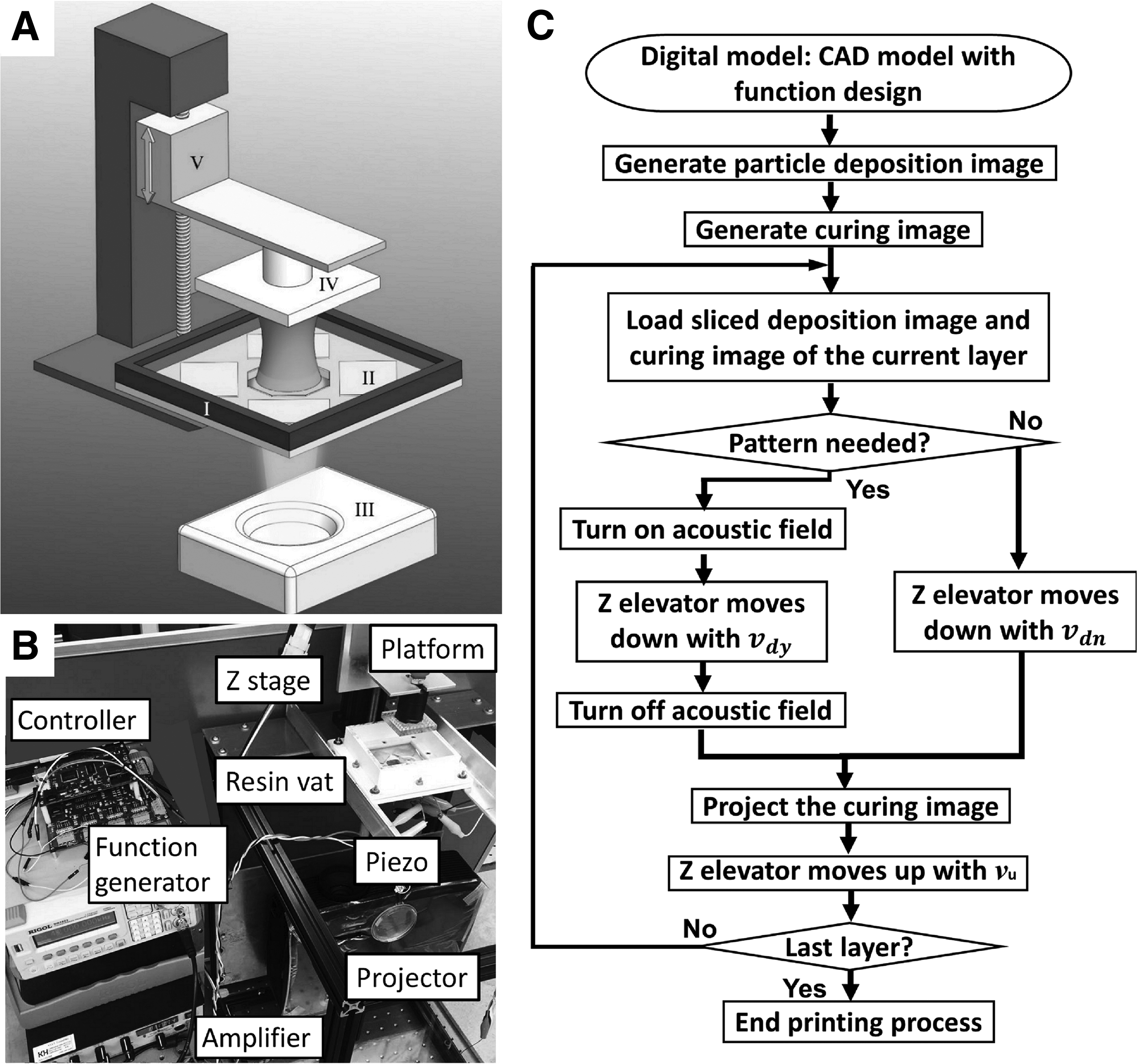
Figure 1A shows the proposed A-PSL system. The main components include a resin vat, several piezoelectric elements, an imaging unit, and a platform that is driven by a Z stage. The resin vat holds the premixed suspension of particle and photocurable polymer. Piezoelectric elements provide an acoustic field for patterning particles in the liquid resin. The imaging unit exposes patterned light according to the digital mask converted from the sliced cross section of the 3D model. Cured layer is built on the platform after the mask image projection. Z stage drives the platform along the Z direction.
The A-PSL system:
A prototype machine was built to implement the proposed A-PSL process. As shown in Figure 1B, it consists of an off-the-shelf projector as imaging unit, a linear stage that elevates the built platform along the Z direction, a motion controller that controls the linear stage, and a resin vat with embedded piezoelectric elements. The base of the resin vat has a window for light to pass through. The printing envelop size is determined by the dimension of this window. The top of the base is covered by a transparent polyethylene terephthalate (PET) film. Four piezoelectric elements are placed horizontally underneath the film at each corner of the vat. A function generator provides the sinusoidal signal at 43 kHz with 5 V peak-to-peak voltage. This signal is amplified by an amplifier and then applied to piezoelectric elements.
Manufacturing process
The proposed acoustic field-assisted SL process is shown in Figure 1C. A digital model with both geometric information and particle pattern information is used to generate particle deposition images and curing images. Particle deposition images provide required information, including filling patterns and areas for filling particles in the polymer matrix properly. The curing image is a digital mask converted from cross section geometry. For each layer, particle deposition image and curing image will be loaded into the main process control program. If the particle deposition image indicates that no particle distribution pattern is needed for the current layer, Z elevator moves down with a relatively fast velocity
After turning off the acoustic field, the curing image will be projected to cure the mixture. Curing time for the particle–polymer mixture was found to be dependent on particle loading fraction in our previous study. 8 Higher particle loading fraction requires a longer curing time to achieve the desired curing depth and layer thickness. Furthermore, the relationship between the loading fraction and curing time is not simply linear. In this study, curing depth experiments as described in our previous study 8 were performed to identify the appropriate curing time for each particle–polymer suspension recipe and layer thickness. Z stage drives the platform up with a speed Vu for the fresh resin to refill after one layer is solidified. A 3D heterogeneous particle–polymer composite product with desired geometries and particle distribution patterns is then built in a layer-by-layer manner by repeating this procedure. During this process, the local composition and particle distribution pattern are precisely controlled through programming the externally applied acoustic field. Hence local particle distribution control and heterogeneous properties are possible to be achieved.
Material
SPOT-E elastic (Spot-A Materials, Sonnaya Ulitka S.L., Barcelona, Spain), a photocurable resin, was selected as the base resin in this study. Observing the particle distribution inside the polymer calls for a translucent color base resin. In addition, the flexibility of this base resin after solidification allows the cured part to be bent or deformed. In this study, four types of particles including tungsten (US Research Nanomaterials, Inc., TX), aluminum (Alpha Chemicals, MO), titanium (Sigma
Multiphysics Simulation
Force analysis
The acoustic radiation force Fr on a spherical particle with radius much smaller than wavelength λ in a nonviscous fluid can be expressed as Equation (1)
23
:
where Vp is the volume of the particle and
where pa is the acoustic pressure and
where
Radiation force drives particles toward a pressure node from a pressure antinode. During travel in the fluid, particles in the liquid resin experience Stokes drag force Fd
14
:
where
Numerical model
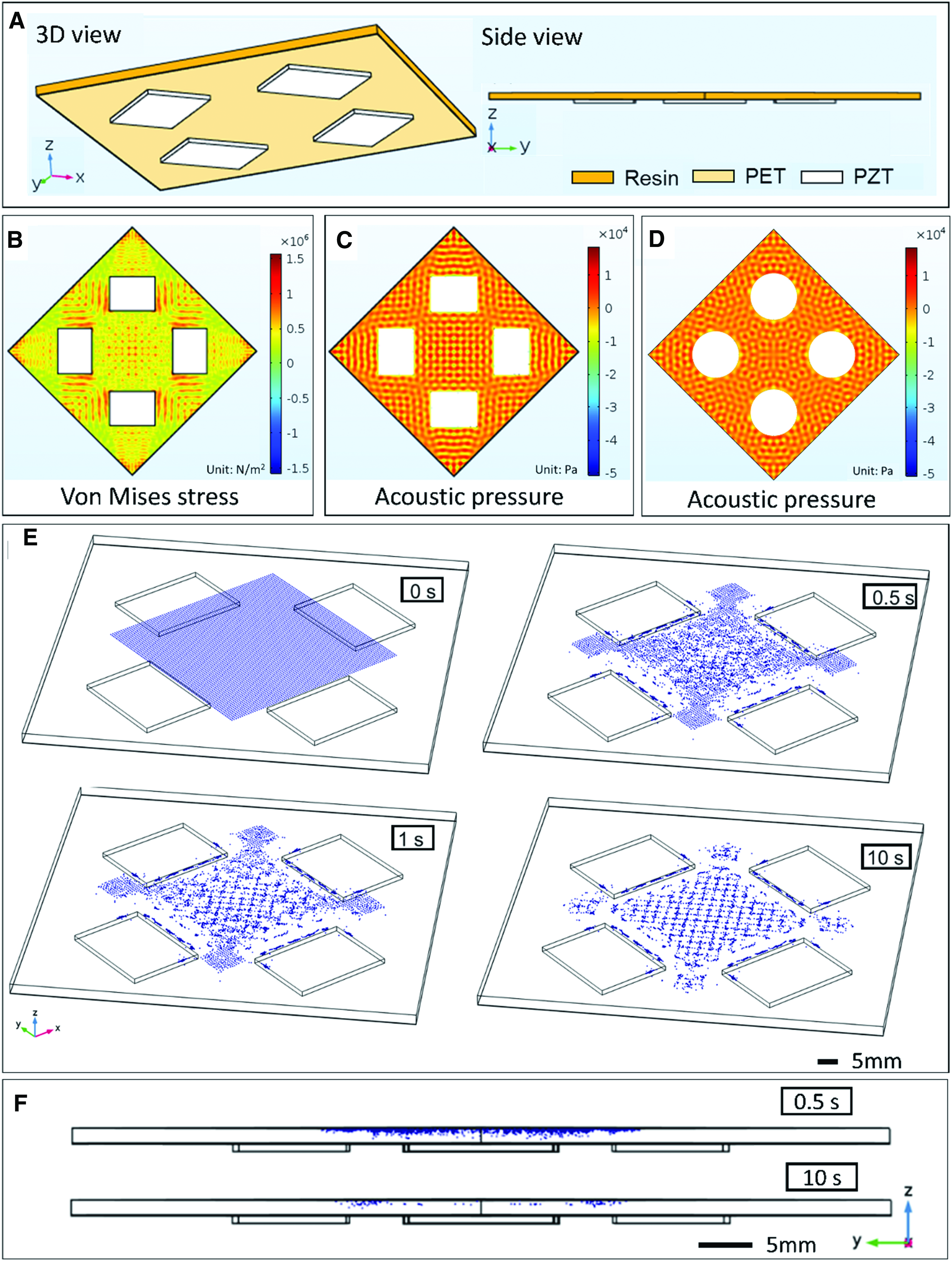
The numerical model of the A-PSL setup was implemented and solved by using finite element software COMSOL Multiphysics 5.2a. Figure 2A shows the geometry and material choices for the finite element model (FEM) to reflect the experimental setup of A-PSL. In the FEM model, a PET film (l: 77.4 mm, w: 77.4 mm, h: 0.13 mm) is inserted between a layer of resin (h: 2 mm) and four piezoelectric plates (l: 20 mm, w: 15 mm, h: 1 mm). “Solid Mechanics–Linear Elastic Materials” physics was applied to the PET domain, “Solid Mechanics–Piezoelectric Materials” and “Electrostatics” physics were applied to the piezoelectric transducer (PZT) domain, and the “Pressure Acoustics” and “Particle Tracing for Fluid Flow” physics were assigned to the resin domain. Boundary condition setups are discussed as follows: the bottom surface of the PZT was set to “roller” condition, the interface between PZT and PET was coupled, the interface between PET and resin was set to “Acoustic-Structure Boundary,” the rest boundaries of PET and PZT were set to “free” condition, and the rest boundaries of resin was set to “Sound Hard Boundary.”
Multiphysics simulation:
To simulate the case when all four PZTs are “on,” a sinusoidal voltage with 100 V amplitude and 43 kHz frequency was applied to the bottom surface of the PZTs, whereas their top surface was set to “ground.” A frequency domain study computed the stress of the PET and the acoustic pressure distribution inside the resin domain, both of which are caused by the PZT actuation. Figure 2B shows the von Mises stress of the PET and Figure 2C shows the acoustic pressure of the resin produced by piezoelectric plates when viewed from the x-y plane along the positive direction of the z-axis. The stress pattern matches very well with the acoustic pressure pattern, indicating that the PZT actuation results in structural deformation of the PET film, which subsequently induces an acoustic field in the resin.
To investigate the effect of piezo element shape on acoustic pressure patterns, the numerical simulation of the A-PSL setup using four piezo disks (d: 20 mm, h: 1 mm) was also performed with COMSOL simulation. The piezoelectric plate and piezoelectric disk were defined with the same piezoelectric materials but they differed in shapes and dimensions. The analytical equations [Eqs. (1–4)] apply to both piezo plate and piezo disk. Numeral simulation of acoustic pressure field patterns produced by piezo disk is shown in Figure 2D. Based on the comparison between Figure 2C and D, it is clear that difference in piezo element shapes will result in different acoustic pressure patterns and consequently produce different spatial distribution of suspended particles as shown in Supplementary Figure S1 (Supplementary Data are available online at www.liebertpub.com/3dp).
After the acoustic pressure has been computed from the frequency domain study, a time domain study (starting at 0 s and stops at 10 s) was conducted to compute the trajectory of the particles dispersed inside the resin domain. The aluminum particles and the Spot-E resin were used as model materials for the simulation. The particle and resin properties are listed in Table 2. The forces applied to the particle include the acoustic radiation force [calculated from the acoustic pressure using Eqs. (1–3)], the drag force [calculated from Eq. (4)], and the gravity force. The particle suspension is modeled as monodispersed with no particle-to-particle interaction. Figure 2E shows the snapshot of particle distribution at 0, 0.5, 1, and 10 s of the time domain simulation. All snapshots are taken from the isotropic x-y-z view. The Supplementary Video S1 showing the evolution of particle distribution with time is included in the Supplementary Data. It can be clearly seen that the particles form a grid-type pattern following the grid-type acoustic pressure pattern. Figure 2F shows the snapshots of particle distribution taken from the y-z plane at 0.5 and 10 s: the initially suspended particles dropped to the bottom of the resin due to gravity as demonstrated by the sparser suspended particles at 10 s compared with 0.5 s.
In sum, the proposed method can locally pattern the particles in 3D space. The piezo elements will generate standing acoustic wave (SAW) patterns on the x-y plane. The acoustic radiation force [given by Eqs. (1 and 2)] will move the par icles to the acoustic nodes at the lowest amplitude indicated by the yellow regions in acoustic pressure field patterns (Fig. 2C, D) or the acoustic antinodes at the highest amplitude represented by the red regions in Figure 2C and D, depending on the density and compressibility of the particles. As shown in the simulation results of Figure 2E, at equilibrium, the originally uniformly dispersed particles will be redistributed following the SAW patterns and thus achieving localized particle pattern on the x-y plane. The localized control of particle pattern along the z-axis is achieved by the layer-by-layer manufacturing process. Note that each layer is parallel to the x-y plane. Hence, by varying the SAW patterns on each layer, the proposed method can also locally control the distribution of particles along the z-axis and hence produce complicated 3D particle distribution patterns.
Results and Discussion
Particle patterning
As indicated by the analytical model and numerical model, the particle dispersion pattern is dependent on piezo element-related parameters, including shape, number, and layout, and process-related parameters, including frequency (i.e., wavelength) and magnitude of power, and/or using piezo element of different shapes (Fig. 2D, showing that circular piezo elements generate different SAW patterns that rectangular elements do) or different combination of shapes, and/or by arranging the locations of the piezo element differently, many more SAW patterns (and thus particle distribution patterns) can be generated. Existing literature on acoustophoresis also showed that arbitrarily particle patterns are possible to be achieved by adjusting the acoustophoresis setup and process settings.24–28
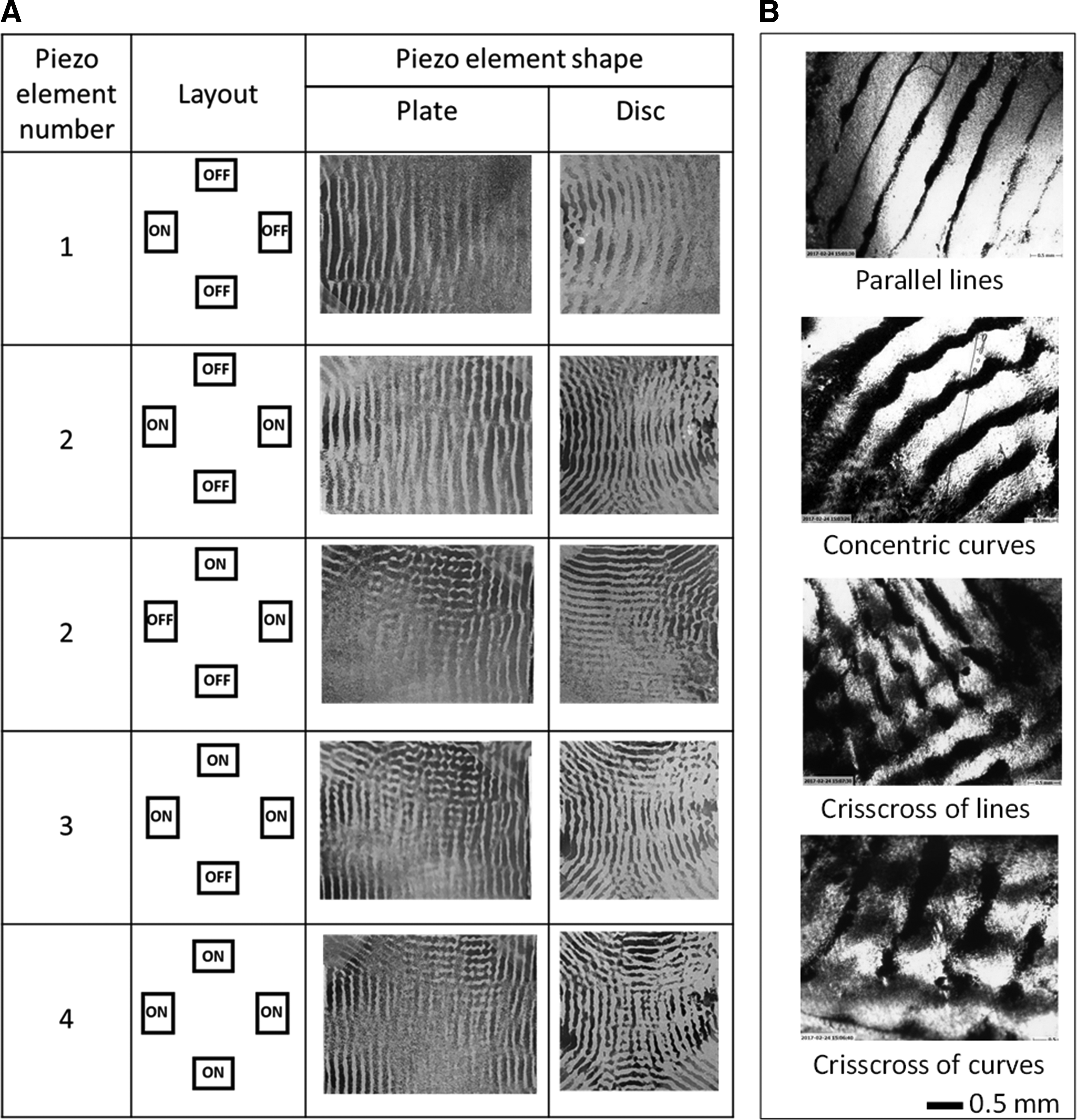
To test the capability of redistributing particles into different patterns using acoustic field in SL systems, experiments have also been designed and performed. Five example patterns are given in Figure 3. In this set of experiments, two sets of piezo elements including four piezo plates and four piezo disks were arranged in a diagonally symmetric way with the applied signal at 43 kHz frequency and 5 V. Five configurations for each piezo elements set were tested and the resulting particle patterns are summarized in Figure 3A.
Various particle patterns:
A rectangular shape piezo plate patterns particles to form parallel lines while a round shape piezo disk forms concentric curves. The basic pairings of piezo elements are the opposite pair and the adjacent pair. With an opposite pair, parallel lines or concentric curves formed by each piezo element are overlapped in the center region. By adjusting the distance between two opposite piezo elements, overlapping can be eliminated or enhanced. By widening the distance, this configuration can be used to create patterns covering a larger area. By narrowing the distance, a denser pattern can be formed. With an adjacent pair, particles are patterned to crisscross of lines or curves. In addition, an opposite pair and an adjacent pair can be actuated simultaneously to obtain combined patterns.
Microscopic images in Figure 3B present various microdispersion particle patterns embedded in the polymer matrix. Parallel lines and concentric curves were assembled by the piezo plate and disk, respectively. Crisscross patterns consisting of lines and curves were generated by the adjacent pair of piezo plates and disks, respectively.
Moreover, four types of particles, tungsten, aluminum, titanium, and copper, were tested and successfully assembled into desired patterns by actuating the corresponding configuration of piezo elements on the A-PSL setup. It demonstrates the capability of patterning various particles with a wide particle size ranging from 70 nm to 75 μm.
Microstructure of particle assembly
To further observe the microstructure of particle assembly embedded in the polymer matrix, microscopic images and scanning electron microscope (SEM) images of an acoustically assembled particle line have been taken. The inset in Figure 4 shows a microscopic image of a line pattern. The line pattern sample was cut along the red dashed line using a blade. The cut plane, which is the cross-sectional plane that is perpendicular to the alignment axis of the particles, was coated with platinum/palladium (Pt/Pd) using E5100 sputter coaters (Polaron Equipment Ltd, Hertfordshire, England), and then observed under the S-3000N SEM (Hitachi High-Tech Instruments Co., Kumagaya, Japan). As can be seen in the SEM image in Figure 4, the particles were assembled intensively into a line with a high particle density and an oval cross section shape. The line cluster of acoustically assembled aluminum particles is measured to be ∼150 μm in height and 400 μm in width. It is reported that the dimension of formed acoustic strap depends on particle loading fraction. 16 Hence the size of the formed line can be adjusted by changing particle loading fractions.
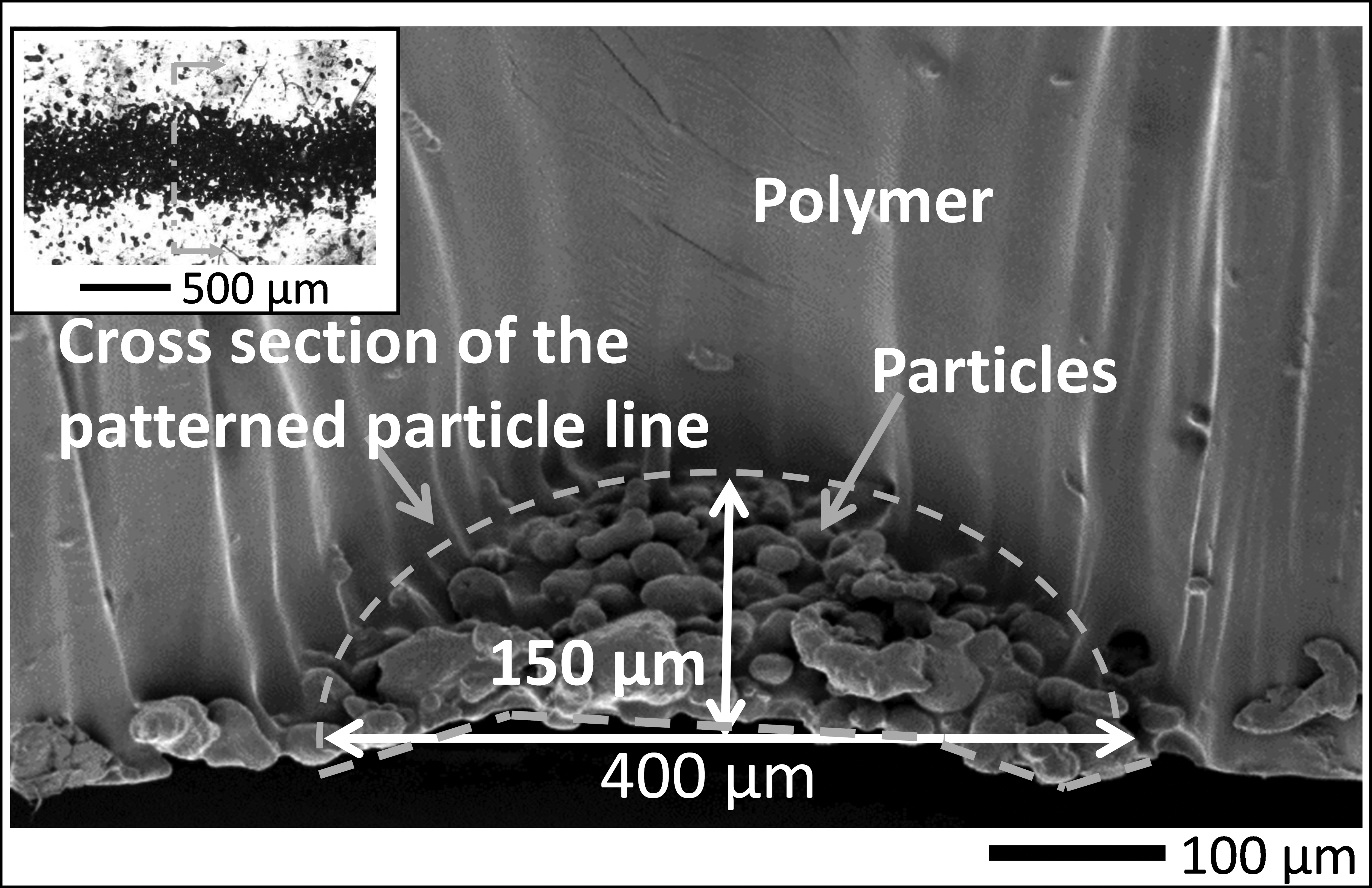
SEM image of the cross section plane of a particle–polymer composite structure. Inset: An image of the acoustically assembled particle line in polymer matrix, black: aluminum particles (30 μm), white: cured SPOT-E elastic resin. SEM, scanning electron microscope.
Printed results
To test the feasibility of integrating acoustic field-assisted particle patterning with the layer-by-layer SL-based 3D printing process, four particle–polymer composite objects with simple geometries but different particle distribution designs were fabricated in the A-PSL setup with four rectangular shape piezo plates. The CAD models are shown in Figure 5. The first object is a single layer part consisted of unidirectional parallel lines of particles. The second part contains a crisscross pattern. The third part is composed of orthogonally aligned particle lines within one layer. The fourth is a multiple layered part with unidirectional aligned particle lines on each layer. The orientation of lines on two neighboring layers is perpendicular. As shown in Figure 5, the employed acoustic field layouts for pattern formation are illustrated in schematics. Printed results for each test case are shown in Figure 5.
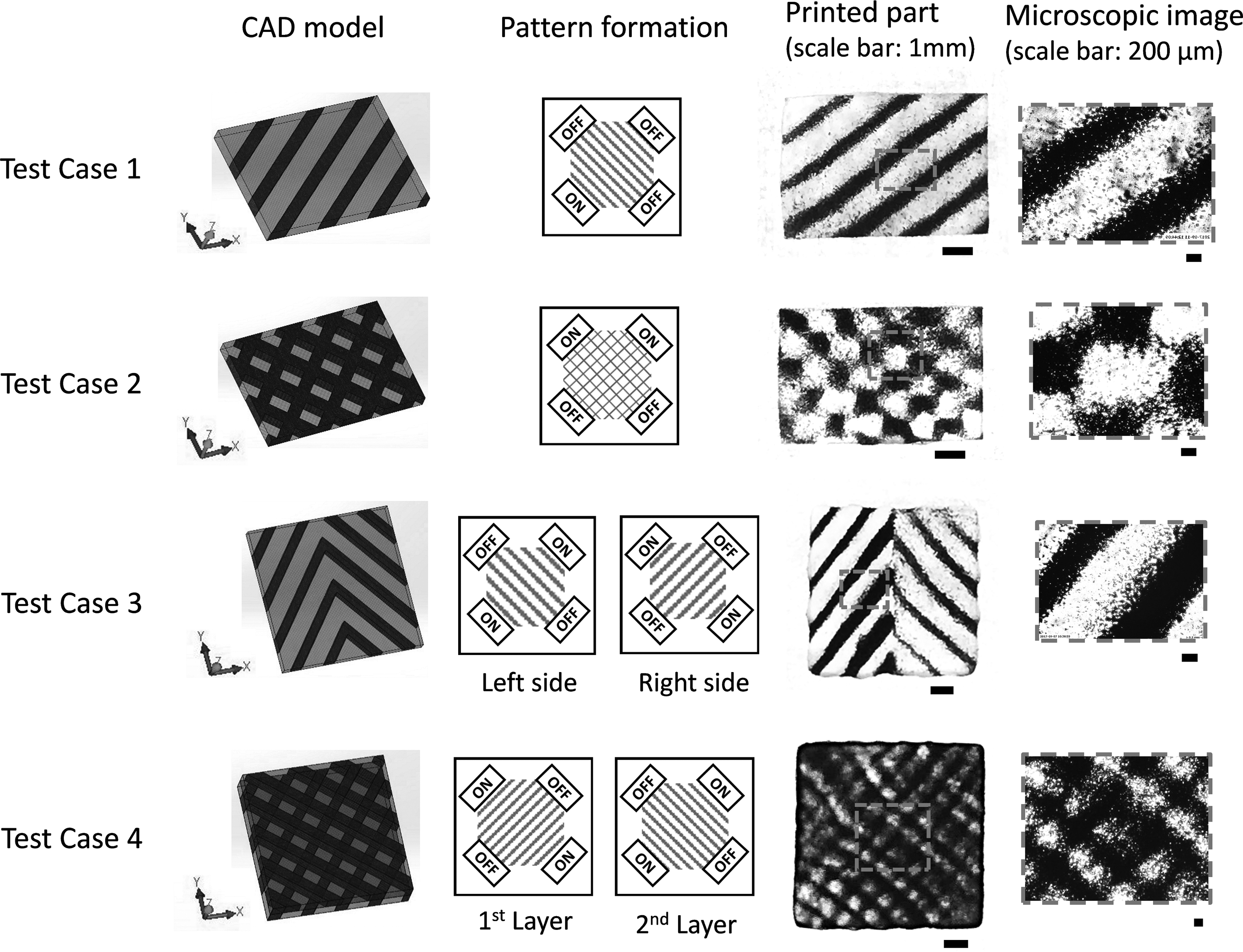
Test cases detailing with CAD models, patterns formation, photographs, and microscopic images of printed parts. Black: aluminum particles (30 μm), clear: cured SPOT-E elastic resin.
Test case 1: A single layer part with uniform line pattern
A block shape part with unidirectional parallel lines covering the entire layer was fabricated. One piezo element was utilized to create the desired particle distribution pattern. From the photograph and the microscopic image of the fabricated part shown in Figure 5, continuous particle distribution patterns can be observed. It shows the capability of the proposed acoustic field-assisted process on fabricating particle–polymer composites with lined particle distribution patterns.
Test case 2: A single layer part with crisscross pattern
A cuboid part shown in Figure 5 was designed to embed particles with a crisscross pattern. As aforementioned, crisscross pattern can be obtained by utilizing multiple piezo elements involving adjacent pair. In this test case, the crisscross pattern was formed by activating an adjacent pair. Crisscross pattern can be observed from the fabricated part shown in Figure 5.
Test case 3: Part with different patterns at different regions of one layer
A cuboid with square cross section was tested as the third case. The particle dispersion pattern was designed to be different on the two halves of one part as shown in Figure 5. To realize the designed particle patterning, two pairs of opposite piezo elements were actuated one by one. The first pair of opposite piezo elements was turned on to form unidirectional lines. Then the left half of the layer was cured. Next, the second pair of opposite piezo elements was actuated to form lines in different orientation on the right side. Last, the remaining area was solidified by projecting the related mask image. From the printed result shown in Figure 5, it can be seen that particles are well distributed with an orthogonally lined pattern within the same printed layer.
Test case 4: Part with orthogonally aligned reinforcement
To test the capability of fabricating multilayered particle–polymer composites in a layer-by-layer way, a multiple layered cuboid part with square cross section was printed. Cross particle distribution pattern was designed as shown in Figure 5. For each layer, one pair of opposite piezo elements was actuated to form uniform oriented lines. By actuating two different pairs of piezo elements, the orientation of lines on each layer is formed with an angle of 90°. Crisscross pattern can be observed from microscopic images shown in Figure 5. It is verified that the proposed manufacturing process can be used to print multiple layers with different particle patterns in each layer
Conclusions
An A-PSL process was successfully developed for fabrication of heterogeneous particle–polymer composite. Assisted by an external acoustic field, dispersion pattern of particles in the liquid photopolymer can be planned and controlled. Various particle distribution patterns were formed and embedded in the polymer matrix. Four test cases with different particle distribution patterns were fabricated to demonstrate the feasibility of the proposed acoustic field-assisted projection stereolithography technology on the production of particle–polymer composites with locally controlled particle distributions.
Future work will (1) further investigate the effect of process settings and acoustic field parameters on particle distribution parameters, to achieve more accurate particle distribution control and more complicated particle distribution patterns and (2) investigate anisotropic property of the printed composites including mechanical property and thermal property.
Footnotes
Acknowledgment
This study is based upon work supported by the National Science Foundation under Grant No. 1663399.
Author Disclosure Statement
No competing financial interests exist.
References
Supplementary Material
Please find the following supplemental material available below.
For Open Access articles published under a Creative Commons License, all supplemental material carries the same license as the article it is associated with.
For non-Open Access articles published, all supplemental material carries a non-exclusive license, and permission requests for re-use of supplemental material or any part of supplemental material shall be sent directly to the copyright owner as specified in the copyright notice associated with the article.