
Abstract
Abstract
Fused deposition modeling (FDM) printers are some of the most common additive manufacturing (AM) systems in use today. One of their most significant drawbacks compared with alternative AM techniques is that they are unable to easily integrate multiple materials into a single process to produce gradient parts, which have different mechanical properties within a single printed object. Much of this limitation comes from the need to have single filaments as inputs to a printed part, and weak bonding between thermoplastics if they are not chemically miscible. In this work, a simple method to actively enhance the bonding strength between chemically immiscible thermoplastics using a static intermixer inserted into the nozzle of a multi-input FDM system has been demonstrated. This system was successfully used to enhance adhesion between rigid and soft, stretchable polymers, which have nearly three orders of magnitude of difference in elastic moduli. The replaceable intermixer within the print head permits direct comparison of side-by-side or intermixed coextrusion processes. The bond strength between adjacent deposited fibers in intermixed printing was found to be at least 12 times higher than that of the fibers in side-by-side printing. As a proof-of-concept, tendon-driven soft robotic fingers with functionally gradient materials produced from mechanically interlocked dissimilar polymers have been printed and characterized. The fingers printed with intermixed coextrusion of hard and soft polymers do not show any noticeable interface failure after 10,000 cycles of operation, whereas other samples printed with side-by-side coextrusion experienced layer delamination before 10,000 cycles. By using a two-tendon system, these fingers have an agonist–antagonist balanced structure to control its stiffness during operation. The soft robotic gripper fabricated from these printed fingers shows its capability to grasp irregular objects with sizes larger than the gripper holder by actuating in both inward and outward directions.

Introduction
In nature, most animals are composed of soft, stretchable, and flexible components enabling them to interact with uncertain environments. In contrast, typical engineered systems or robots are primarily composed of rigid hard materials allowing precise control of position in three-dimensional (3D) space. 1 However, this rigidity limits the applicability of traditional robots to only particular environments. For instance, hyper-redundant robotic systems are composed of serially connected rigid links with a high degree of freedom resembling biological systems. 2 These systems have a high degree of articulation making them superior in highly constrained environments. 3 However, due to their dexterity and compliance, finger systems with a continuous soft body have also gained popularity. 4 A tendon system can also be used to actuate both hyper-redundant and continuum bodied robotic systems. 5
Inspired by soft-bodied biological systems, much of the recent work in soft robotics has been implemented by developing tendon-driven artificial fingers, such as prosthetic fingers, 4 or shape memory alloy-driven caterpillars. 6 A fully soft-bodied system experiences actuation lag due to its deformation at the tendon/soft matter interface. Integrating soft and rigid materials in a single actuation system would facilitate actuation response. However, this integration is not simple for the commonly used molding–casting fabrication processes, which require user expertise.7,8 These techniques also place a limit on the structural complexity achievable in the soft robots because of the processing requirements of molding and demolding steps.
The limited structural complexity is one of the reasons the natural biological systems outperform engineered systems. Emerging 3D printing technologies have a role to play to enable printing of geometrically complex soft-robotic structures, such as a combustion-powered robot, 9 a hydraulic hexapod robot, 10 a legged soft robot, 11 a prestressed soft gripper, 12 and a tentacle-like artificial muscle. 13
For untethered applications, soft robots can benefit from the inclusion of some rigid components with their soft body. 14 The rigid and soft materials may not be readily bonded, and this can result in recurring adhesion failures at the interface between different parts. Therefore, a novel 3D printing technique engineered to print both rigid and soft materials resisting separation of chemically immiscible polymers once printed is of high value to the field of soft robotics manufacturing as it can help bypass many of the challenges of assembling and bonding parts in the final manufacturing process.
In additive manufacturing (AM) processes, a part is produced by adding material into successive two-dimensional (2D) cross sections. 15 In a multi-material fused deposition modeling (FDM) technique, multiple polymers are used in the same system to print objects with specialized materials at strategic locations within the volume to increase functionality and performance. 16 In 2000, fused deposition of multiple ceramic was developed, which is an extended version of the FDM technique to print objects with up to four ceramic materials. 17 Pilleux et al. used a multi-material FDM system to print structures consisting of an alumina base material and a support material made of wax. 18 In a recently published work, functionally gradient material (FGM) devices were successfully printed using an off-the-shelf FDM-style 3D printer. 19 The composition was controlled by regulating the feed rates of two filaments. However, there was no intermixing function in this system, and blending of nylon and polylactic acid (PLA) was said to be uneven and could often result in globs rather than smooth extrusion.
The limitation of multi-material FDM systems using separate nozzles for each material is that they are unable to print FGM devices with a gradual transition from one material to another. This gradient may be crucial for functional devices for reducing internal stress gradients and delamination. Kumar et al. successfully printed graded conical end effectors having enough anchoring stability compared with other purely soft or rigid objects 20 but had to make use of a different AM technology to achieve this result (Connex500 printer based on PolyJet Matrix™ Technology). Bruyas et al. also printed statically balanced compliant joints using a multi-material polyjet technique. 21 This type of printing is useful but can only produce parts from specialized resins, which may not have the same attractive properties as true engineering polymers. For instance, Lee et al. reported that the 3D printed connectors printed from resins were easily torn. 22
Multi-material FDM systems with a single nozzle for all materials can, in theory, be used to print true FGM objects by continuously varying the composition of the extrudate in 3D space. There are very few FDM systems, which can print two or three thermoplastic materials using the same nozzle system,23–25 and most of these multi-material FDM systems have been used with multiple filaments of the same material but with different colors so that materials bond well and also have no mechanically different performance.
When polymers are printed with simple side-by-side coextrusion, the adhesion between the materials at their interface is crucial to prevent potential delamination and other bonding issues. If the Hildebrand solubility parameters, δ (cal1/2cm3/2) of two polymers are comparable, the materials are miscible. 26 In this case, due to mutual diffusion, the polymer pair has a symmetric concentration profile of both polymers without a sharp transition, 27 which makes the polymer pair less prone to bonding failure. If the difference between the solubility parameters of the polymers increases, they become immiscible. 26 In the case of an immiscible polymer pair, they are likely to have bonding failures at their interface. There are some reported compatibilization methods to enhance bonding at the interface of two immiscible polymers.28–31 However, these techniques are designed for flat sheets of polymers and are not suitable for FDM systems without additional processing steps.
As an alternate solution to this issue, mechanical approaches to resist separation of the polymers at their interface can be applied. 32 Mechanical interlocking or keying is one of the conceptually most straightforward approaches to overcome the bonding failures of polymers with the FDM technology. Mechanical keying refers to the process of joining two highly rough solid surfaces by physically engaging them to introduce adhesion between them. Compared with other blending structures of immiscible polymer melts, a co-continuous structure facilitates a synergistic effect on the mechanical modulus from each constituent polymer. 33 However, to ensure the co-continuous structure of a pair of polymer melts, the volume fraction of any material should be in the range of 0.3–0.7 if the viscosity ratio is near unity. 33
Therefore, when switching from one material to another during 3D printing, at a 3D volume where the composition does not satisfy the requirements of the co-continuous structure, it will have one material continuous with a dispersed phase of the other material. However, in the majority of the print volume, the co-continuous structure should be realized and thus have enhanced adhesion between layers compared with the case of side-by-side coextrusion. Hence, an extruder head with the capacity to partially intermix immiscible polymers to introduce mechanical keying and ensuring the co-continuous structure of constituent polymers is highly useful for multi-material FDM. This capability can be used to directly print FGM soft robotic fingers with hard and soft components.
In this article, a multi-material extruder system with the capacity to insert a static intermixer enabling extrusion of a mechanically interlocked extrudate of two chemically immiscible polymers is reported. It was developed first to demonstrate that two rigid thermoplastics that bond poorly, acrylonitrile butadiene styrene (ABS) and high-impact polystyrene (HIPS), could have strongly enhanced bonding. The degree of intermixing or mechanical interlocking is a key to analyze the performance of the static intermixer. Samples printed with intermixed coextrusion were compared with samples printed with side-by-side coextrusion without the intermixer. It was the first step to confirm the capability of printing FGM devices using this custom extruder system. A custom system for printing styrene–ethylene–butylene–styrene (SEBS) elastomers was used to examine bonding between SEBS and HIPS with approximately three orders of magnitude difference in moduli. Once the bonding between layers was found to improve due to the intermixing, a variety of tendon-driven fingers with both rigid and soft components were directly printed. Afterward, the actuation force and bending angles of the fingers with different geometries were measured to identify optimized design. Finally, a fully compliant, tendon-driven soft robotic gripper was fabricated, and its performance was measured.
Materials and Methods
Materials
Filaments of rigid plastics, ABS and HIPS, sourced from Filaments.ca were used as received. Pellets of SEBS with the commercial name Kraton G1657 was used as a soft elastomer for rubbery printed parts.
Printing using intermixed coextrusion
Using a custom bracket cut by a CO2 laser from 6-mm-thick acrylic sheet, a tri-extruder head was assembled and attached to an inexpensive 3D printer purchased from Geeetech, China. An early version of this extruder, the bi-extruder was reported in our previous work. 34 This tri-extruder has three input channels, two of them were intended for feeding thermoplastic materials, whereas the third input was kept unused by sealing with an M6 screw. The complete printer setup is shown in Figure 1a, and a close view of the assembled tri-extruder is presented in Figure 1b. An exploded 3D model of the dissembled tri-extruder can be found in Supplementary Figure S1a. The detailed drawings of the extruder head are given in Supplementary Figures S2 and S3.

A helical intermixer as shown in Figure 1c was designed and fabricated using Direct Metal Laser Sintering (DMLS) of 316-stainless steel powder by Proto Labs, Minnesota, with 20 μm resolution. The intermixer has an overall diameter of 3.5 mm, which can be inserted into a nozzle having an internal diameter of 4 mm. The 3D model of the intermixer is given in Supplementary Figure S1b. The intermixer is kept static, and polymer melt flows around the intermixer with mixing achieved by chaotic advection of the melt flows. 35 Mixing comes at the expense of extra resistance to flow, with longer static intermixers providing better blending but more losses from friction.
Inserting the intermixer into the nozzle enables intermixed coextrusion, whereas, without the intermixer, simple side-by-side co-extrudates are achieved. To ensure that intermixing has no adverse impact on the quality of the extruded filaments, intermixed extrudate samples and side-by-side extrudate samples of ABS and HIPS were produced and compared for their fracture strength. Figure 1d and e shows microscopic images of side-by-side and intermixed co-extrudates of red HIPS and blue ABS with the same (1:1) volume fraction, respectively. The co-continuous structure of HIPS and ABS was observed from their cross-sectional microscopic images. It was also found that the ultimate strengths of intermixed co-extrudates with different composition were comparable with those of side-by-side co-extrudates with the same polymer compositions, which indicate that the intermixing does not result in any voids or axial discontinuities in the material composition that could result in early failure of the extrudates.
Preparation of 2D planar samples
Planar samples with a single layer thickness are used to test the average adhesion strength of adjacent deposited fibers. First, rectangular sheets with different compositions of ABS and HIPS having only a single layer were printed with linear infill lines aligned along either the X or Y axes of the print bed. The test specimens were then cut from the rectangles by a CO2 laser cutter. The dumbbell-shaped samples, as per ASTM D1708 guidelines, 36 were cut to align the deposited fibers perpendicular to the loading direction. The ultimate strength of these samples represents the interfiber adhesion strength. Microscope images of the cross sections where the samples failed were carefully examined to determine the mode of failure. Sections cut by a scalpel were used for image analyses of the original cross section of the samples.
In the case of side-by-side coextrusion (without intermixer), there are two types of samples, X-samples and Y-samples, with a distinctly different appearance. The X-samples are cut from the rectangle sheet, which was printed by depositing infill fibers aligned with the X-axis, whereas the Y-samples are from the sheets printed with infill fibers aligned with Y-axis. Figure 2a shows the orientation of the print head and the directions of the print axes while printing X-samples. It also shows microscopic images of the sections across the deposited fibers. Figure 2b shows the details of Y-samples and confirms that the cross sections of Y-samples have more of a true alternating arrangement, which further reduces the degree of same-species diffusion of polymers. Figure 2c presents the dimensions of these 2D planar samples. The samples printed with intermixed coextrusion do not have such an effect of print orientation; instead, the nature of intermixing is random without any pattern, as shown in the microscopic image in Figure 2d.
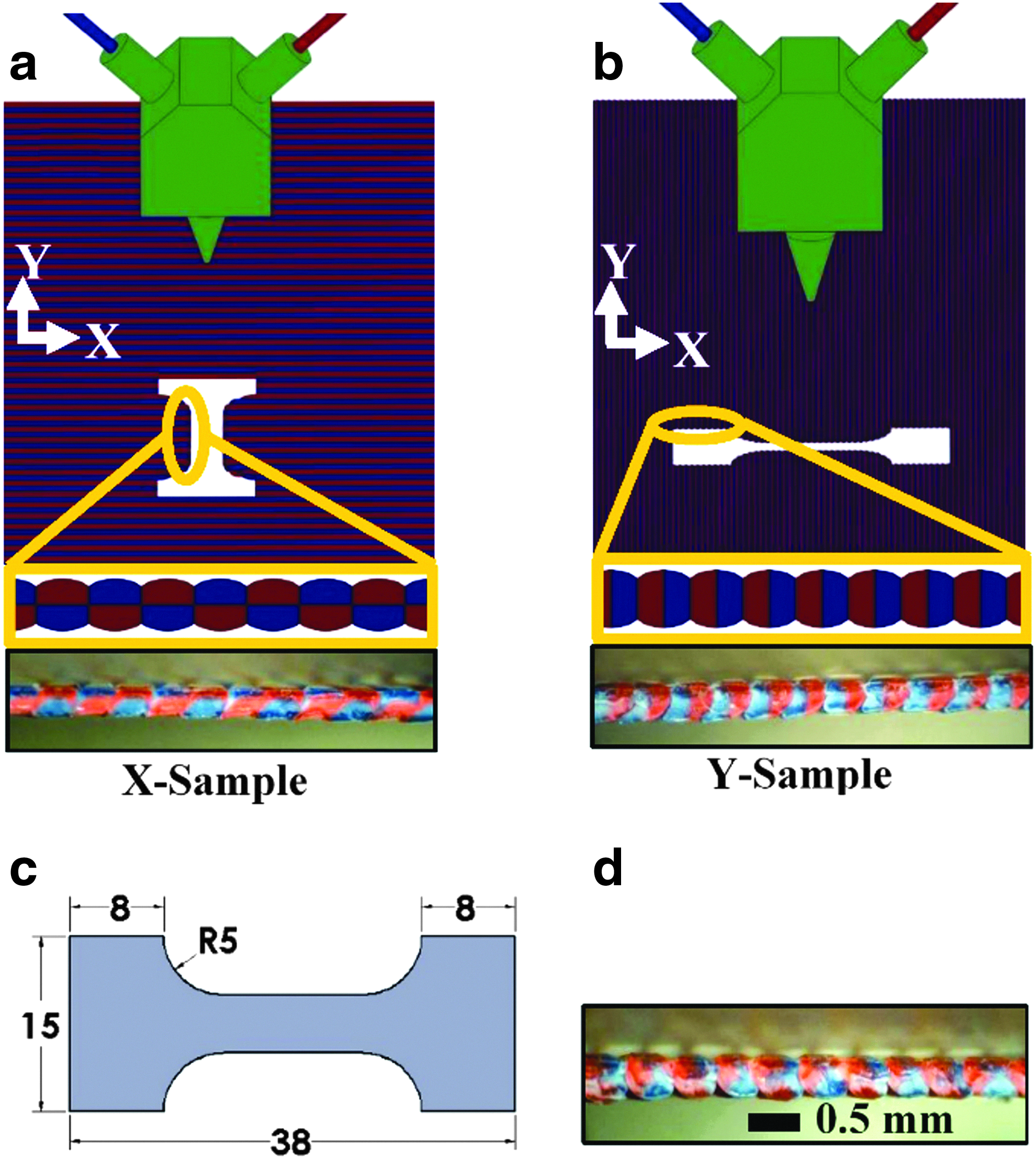
The print orientation and microscopic images of flat sheets printed for
Preparation of 3D samples
3D dog-bone-style test coupons were printed for ultimate strength testing based on a version of ASTM D638-10 standard. The ASTM guideline has five different test coupons, type I to type V. A modified test coupon of type V was used for this study following the similar method reported in the liturature 37 to balance print size and load cell limits for our material testing system. Photos of 3D samples of different composition of red HIPS and blue ABS printed with both types of coextrusions are depicted in Supplementary Figure S4. These samples were printed using 0°/90° raster angles with each alternating layer having a 0.5 mm layer width and a 0.4 mm layer height. The print-bed temperature was set at 90°C during printing.
Design of tendon-driven finger
The finger designed in this work has four main components: a flexible main structural body, two rigid channels for the tendon systems, two soft rubbery layers on both gripping surfaces, and two inextensible tendon systems. Figure 3a shows these components where the capability of the bidirectional actuation system of a finger can be seen. The flexible main body serves as the backbone of the finger. The overall stiffness of the finger is determined mainly by the composition and thickness of this flexible backbone. In this work, eight different finger samples (A to H) were designed and characterized to compare their actuation forces and bending angles with respect to the tendon displacement. These fingers differ in thickness or composition of their backbone unit, as illustrated in Figure 3b. Except for sample F, all other samples were printed with an intermixer inserted.

Samples A and B have identical dimensions with a 2-mm-thick backbone unit. The only difference is that sample B is printed entirely from SEBS. Unless explicitly mentioned, when switching between red HIPS and transparent SEBS during printing, the composition was changed gradually within four layers. This gradual transition of HIPS and SEBS can be seen in Figure 3c. When these fingers are actuated, one side of the finger will be under compression, whereas another side will be under tensile loading. As they are symmetric, the neutral axis lies on the geometric center line of the finger. Both samples C and D have a 4-mm-thick backbone unit; however, sample D has one 100% HIPS layer at the neutral axis of the finger to enhance overall axial stiffness. This stiffness-enhancing HIPS layer with abrupt transition can be seen in Figure 3d.
Samples E, F, and G have an 8-mm-thick backbone unit with different composition and extrusion type. The backbone units of samples E and F are entirely composed of SEBS but printed with intermixed and side-by-side extrusion, respectively. However, the backbone unit of sample G is composed of 33% HIPS and 67% SEBS. Finally, sample H has a thicker SEBS backbone unit with 12 mm thickness. All these samples have a 1-mm-thick SEBS layer on the upper surfaces of the rigid channels on both sides to increase the coefficient of friction of the gripping surface. The dimensional comparison of these samples can be found in Supplementary Figure S5.
Nylon string was used as an inextensible tendon for the fingers. A rectangular channel within the rigid pillars was used for the tendon system. The purpose of having extended upper surfaces of these pillars is to increase the grasping contact area. It is necessary to have a rigid channel for the tendon to avoid deformation of these individual sections when actuated. Each of the fingers has two tendon systems on both sides to enable bidirectional actuation. Another advantage of this bidirectional actuation is its agonist–antagonist balanced structure, which ensures that the finger can hold an actuated position even when being loaded. The free end of the finger has a slope to avoid edge contact with the object when actuated.
Results and Discussion
Tensile tests of 2D planar samples
Once the 2D planar samples are prepared, they were tested with an ElectroForce® 3200 Series III Test Instrument to compare the interfiber adhesion of samples printed from side-by-side and intermixed coextrusions. The side-by-side Y-samples have the closest to true alternating materials across the infill lines, which provide the most favorable condition for delamination. In contrast, the X-samples demonstrate some degree of same-species polymer diffusion near the center of the interface of two adjacent deposited fibers as shown in Figure 2a. Intermixed samples show much more mechanical keying in the individual deposited fibers by possessing the co-continuous structure of both HIPS and ABS. After tensile testing, the cross sections of all the samples at their failure locations were photographed under a microscope to determine the mode of failure. It was determined that all the side-by-side samples failed by separation of two fibers having weakest adhesion at their interface, suggesting adhesive failure mode. The following sections describe the effect of significant printing parameters on the adhesion strength of these samples. Table 1 lists ranges of all the parameters tested while printing the 2D samples examined in this section. When printing the samples to test the effect of a particular factor, other factors were kept fixed at the mid-level in Table 1.
Factors with Their High, Low, and Mid-Levels
Effect of nozzle temperature
Nozzle temperature is a very important factor to be considered in FDM printing. In FDM, the nozzle temperature governs the temperature of the deposited fibers being adhered to the previous fiber. 38 This initial temperature of just deposited fiber controls the degree of thermal motion such as reptation and diffusion of polymer chains across the interfaces of deposited fibers. Therefore, a higher nozzle temperature results in higher adhesion strength of adjacent layers. However, excessively high nozzle temperature may also induce degradation of the polymer materials, so it cannot be increased indefinitely without cost. From Figure 4a, higher extrusion temperatures increase adhesion strength for all types of printing, but in all cases, the intermixed adhesion strengths were the highest. Y-samples showed very weak bonding compared with X-samples, which is true for all the tests performed in this section. This phenomenon indicates a major weakness of side-by-side coextrusion in manufacturing robust gradient parts as these interfaces will result in substantial bond weaknesses within larger components.

The effect of
Effect of layer width
The layer width is defined by the user while slicing the object. A higher layer width increases the polymer extrusion rate. Therefore, if the air gap between each deposited fiber is kept the same that results in a larger overlap between adjacent deposited fibers, it reduces voids within the fill volume and favors the thermal movement of polymer chains because of more contact area, overall resulting in higher adhesion strength. A larger layer width also slows down the cooling due to more thermal mass 39 ; thus, it increases the degree of diffusion of polymeric chains through the fiber interface. Increasing layer width increases the apparent adhesion strength between fibers, as shown in Figure 4b, but it primarily improves bonding between filaments due to increased bonded area.
In this analysis, the adhesion strength was estimated based on the thickness of the sample, assuming the cross-sectional area to be the same for all samples with different layer width. An increase in layer width from 0.35 to 0.65 mm resulted in over 70% increase in adhesion strengths in intermixed samples. For side-by-side X-samples, this increase in average adhesion strength was only ∼25%. In Supplementary Figure S6, the adhesion strength corrected for the measured thickness is presented where the layer width effect disappears, confirming that the increased contact area due to higher overlapping caused the apparent increase in adhesion strength.
Effect of print speed
The effect of print speed is not as significant as layer width, but it also plays a role in governing the adhesion between adjacent fibers. Faster print speed enhances adhesion strength, as shown in Figure 4c. In the case of higher print speed, each fiber has less time to cool before the next fiber is deposited, resulting in more diffusion with newly deposited fiber. Hence, samples printed with 90 mm/s have on average 40% higher adhesion strength compared with samples printed with 30 mm/s. In the literature, 40 a similar effect was also observed by Pan et al. However, as the print object size increases this effect seems to diminish because the deposited fibers take only on the order of a few seconds to cool down, hence imposing a time limit for improved adhesion.
Figure 4d explains the mode of failure in the case of side-by-side (X-samples) and intermixed samples with a 1:1 ratio of red HIPS:blue ABS. In the inset images, the microscopic images of the failed cross sections of 2D samples are shown. The side-by-side (X-samples) have an obvious bimorph structure of the polymers resulting in delamination dominated adhesive failure. However, the intermixed samples show a combination of adhesive and cohesive failures as depicted in the inset image, which contributes to the higher layer adhesion of deposited adjacent fibers.
Tensile tests of 3D: object samples
3D samples were also tested on the same ElectroForce® 3200 Series III Test Instrument to measure the ultimate tensile strength (UTS) of side-by-side and intermixed samples. Each data point of this analysis represents the average strength of three repetitions, and the overall consistency of measured strength demonstrates that intermixing enhances the mechanical strength of 3D objects of ABS and HIPS. From Figure 4e, pure HIPS and ABS samples showed an average tensile strength of 20.44 and 30.06 MPa, respectively. As the composition of ABS increases, the UTS of the sample also increases for both intermixed and side-by-side extruded parts, roughly suggesting the rule of mixture holds for these parts despite potential bonding challenges.
In all cases, the intermixed 3D samples showed more than 10% higher UTS than their side-by-side extruded counterparts, which is not as significant as the 2D samples. This can be attributed to the fact that in 3D structures the materials are already partially interlocked in all three directions due to different fill angles and the subset of filaments already aligned in the direction of the loading. After the tensile tests, the fractured samples were imaged and examined to understand the mode of failure better. As expected, the side-by-side samples (Fig. 4f) showed significant interlayer delamination, which was not seen in the case of intermixed samples (Fig. 4g).
Characterization of tendon-driven fingers
To compare the performance of different finger samples, the actuation force and deflection angle generated by the fingers were measured for different tendon displacements. These properties are mainly determined by the overall stiffness of the finger. The ideal finger should have a higher actuation force and a higher deflection angle for a specific tendon displacement. Once the tests are performed, the best sample finger was used to develop a compliant gripper.
Actuation force measurement
An acrylic support was designed to hold the fingers horizontally to ensure that the tip of the finger barely touches another flat acrylic sheet, which is fixed to a load cell (Transducer Techniques, MLP-10) held by acrylic support. A National Instrument motion controller (Model No. ESP301) along with a data acquisition (DAQ) hub (NI USB-6289) and a Windows Presentation Foundation (WPF) application written in C# were used to apply tendon displacements and measure the corresponding actuation forces. The test setup is presented in Figure 5a, and the variation of measured actuation forces for different tendon displacements of all samples is shown in Figure 6. Samples A and B showed relatively higher bending angles and lower actuation forces compared with the other samples.
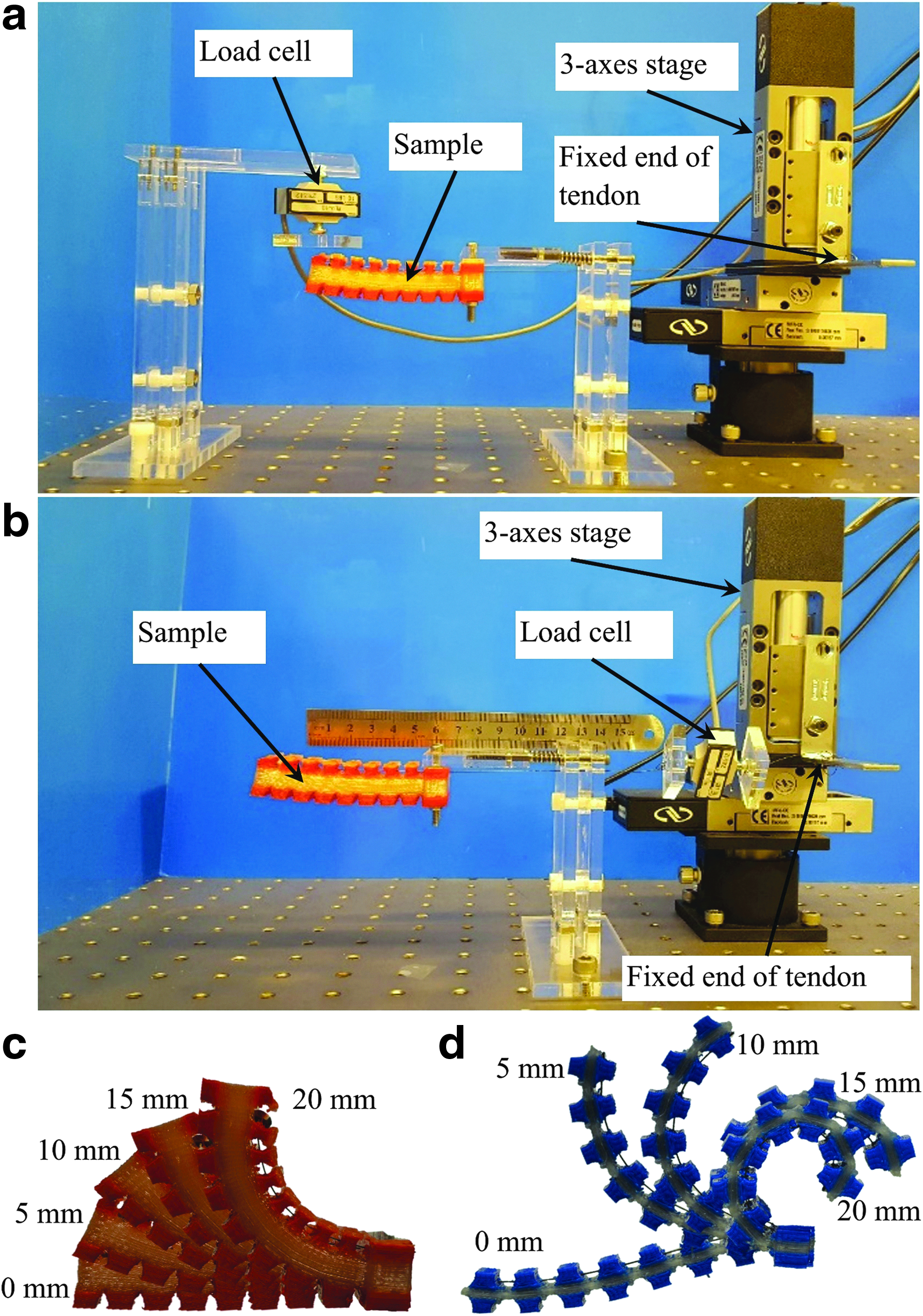
Test setup to measure
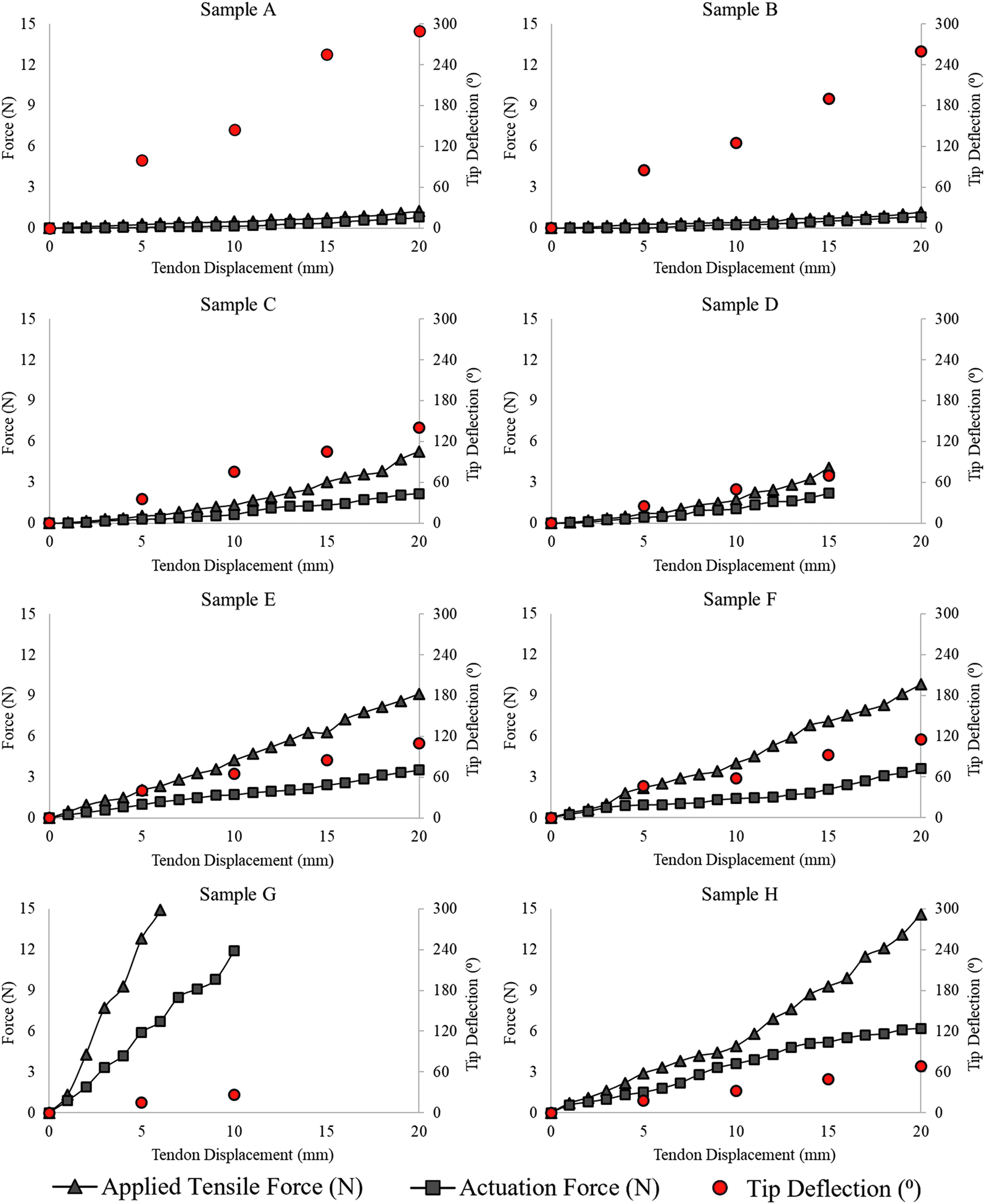
The measured tip deflection, actuation force, and applied tensile force for different tendon displacements applied on sample A to sample H. Color images are available online.
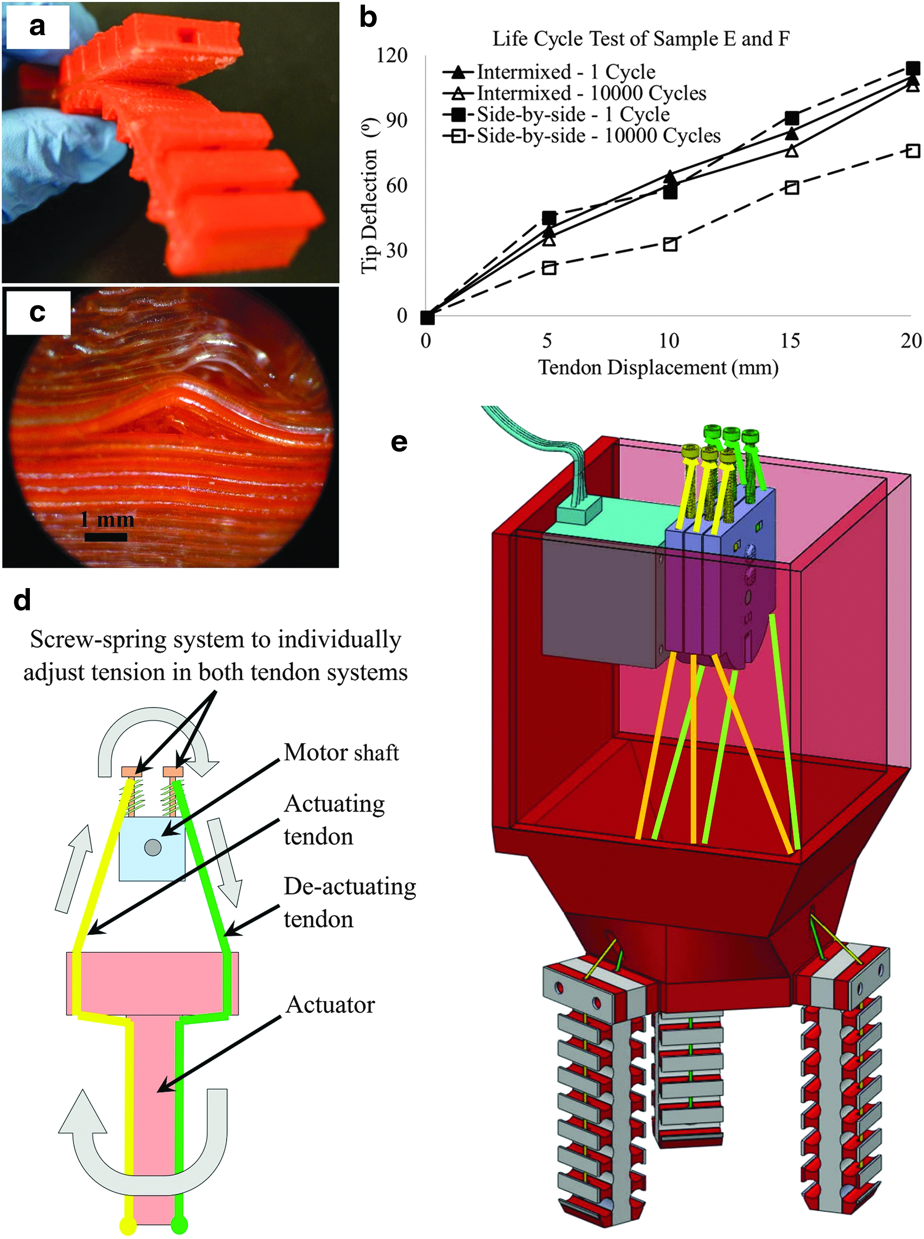
Sample G was found to generate the largest actuation force up to 10 mm of tendon displacement. The actuation force of this sample was even larger than that of sample H with the thickest (12 mm) flexible backbone unit because it was stiffest in bending. Sample D experienced major interface failure when actuated by a 15 mm tendon displacement. A close observation, as shown in Figure 7a, indicates that this failure was mainly because of the sharp transition between HIPS and SEBS—further evidence of the importance of gradient and intermixed parts. Hence, from the perspective of actuation force, samples E, F, and H showed the best potential to be used in compliant grippers.
Displacement angle and tensile force measurement
Another acrylic support was designed to hold the fingers horizontally and keep one end of the finger fixed as a cantilever beam. Then, the tendon cable was attached to one side of a load cell and another tendon was attached from the other side of the load cell to a three-axis stage. The same DAQ system was used to measure the linear displacement of the tendon cable and corresponding tensile force applied through the tendon cable. A high-speed camera was positioned horizontally to capture the images of the deflected finger. A ruler placed beside the finger was useful when measuring the deflection angles via image processing. Figure 5b shows the experimental setup to measure the angles of deflection and applied tensile force of the fingers. Figure 5c and d shows successive actuation of two samples with different stiffnesses. The sample with only a 2-mm-thick backbone unit has low stiffness, which is confirmed from its higher tip deflection, whereas another sample with an 8-mm-thick backbone unit results in much less actuation for the same amount of tendon displacement.
From Figure 6, sample A shows the highest bending with a lower tensile force requirement, indicating that its stiffness is the lowest. Sample B also shows a similar trend; however, its deflection angle is slightly less than that of sample A. This is believed to be caused by the fact that under tendon displacement the soft tendon channel is also deformed nullifying some degree of actuation by the tendon. By increasing the thickness of the backbone unit to 4 mm, samples C and D require higher tensile force to actuate to a certain angle. This force requirement was highest in the case of sample G, which had an 8-mm-thick flexible backbone unit with a 4-mm-thick semirigid backbone unit. It was necessary to apply more than 15 N tensile loads to continue actuation after a 5 mm tendon displacement with very limited deflection angle. Sample H showed reasonable deflection with actuation force; however, its tensile force requirement was also noticeably higher than that of samples E and F.
Therefore, based on the actuation force, angle, and tensile force requirements, samples E and F were found to have potential to be used in developing the compliant gripper. These two samples have the same dimensions and construction with the only difference being their constituent extrudate type, intermixed versus side-by-side. To further examine the effect of extrudate type on the actuation performance of the finger, a cycle test was conducted where the fingers were actuated 10,000 times in both directions. In this study, a complete cycle includes actuating the finger in one direction, de-actuating back to neutral position with the same tendon, actuating again in the other direction with the other tendon, and finally de-actuating back to the neutral position. The deflection angles of both fingers before and after the cycle test were plotted, as shown in Figure 7b.
It was found that although the intermixed sample E does not show any major discrepancy in deflection angle after 10,000 runs, sample F printed with side-by-side coextrusion results in a noticeable decrease in deflection angle after the cycle test. To understand the reason behind this phenomenon, both the samples were carefully observed under a microscope. At no actuation condition, no changes were visible. However, when they were actuated and observed under the microscope, it was found that the side-by-side sample F showed localized, small-scale layer-wise delamination (as depicted in Fig. 7c) at selected HIPS and SEBS interfaces where hard HIPS and soft SEBS were in poor contact. Sample E did not show any such failure even after 10,000 cycles. This study confirms the necessity of intermixed coextrusion of two mechanically distinct polymers in gradient printing to eliminate anisotropy in mechanical properties resulting from printing orientation.
Stiffness measurement
The tensile force required to actuate the finger was measured over a range of tendon displacements as discussed above. This tensile force showed a nearly linear relationship with the tendon displacement. Hence, the overall stiffness of the finger can be calculated, as carried out by Mutlu et al., 4 as the linear fit slope of the tensile force versus tendon displacement plot as shown in Figure 6. The deviation of these plots from a linear fit is believed to be caused by the gap between tendon cable and its channel, possible slack in tendon cable, slight initial stretching of the cable itself, and the deformation of the finger. The measured actuation force generated by the finger was substantially smaller than the tensile force applied through the tendon cable. This mechanical loss may be due to different forms of losses such as friction between tendon and finger, the energy dissipated to deflect the finger, and loss due to deformation in soft components.
Development of a fully compliant gripper
Finger E was found to have the best performance based on all the analyses, so two more fingers were printed with the same dimensions. A fully compliant gripper with three fingers was constructed to demonstrate the conformity of the proposed fingers with both hard and soft components. Three tendon cables from each finger form a set of tendons. Hence, there are two sets of tendon systems: one set is for actuating all fingers toward the inward direction of the gripper, whereas the other set actuates them outward. The inward tendon system is actuated when a grasping action is desired, whereas the outward tendon system is actuated when a releasing action is required. Due to the ability of these fingers to actuate in both directions, the gripper can grasp objects that are larger than its size.
It was necessary to make sure that all the tendon cables actuate at the same time, which was ensured by keeping both sets of tendon systems always in tension. Figure 7d shows a schematic diagram of a finger depicting its agonist–antagonist balanced structure. With the help of a screw-spring mechanism, each tendon can be adjusted individually to control the tension. The tendons were attached to an acrylic rotor, which was coupled with the shaft of a stepper motor. As shown in Figure 7d, if the motor rotates in a clockwise direction, it induces tension in the yellow tendon and reduces tension in the green tendon. That results in an outward actuation of the fingers as shown in the figure. This agonist–antagonist balanced system ensures that the displacements in both tendons remain the same with the opposite direction.
The 3D model in Figure 7e was based on red HIPS and transparent SEBS with green inward and yellow outward tendon systems. The actual gripper was successfully used to handle different-sized objects with nongeometric irregular shapes softly. Figure 8 shows time-lapse images of the gripper where it was used to grasp a ceramic table clock. This action starts with outward actuation to open the gripper, followed by a no-actuation step when it surrounds the object being handled. Then, by actuating in the inward direction, the fingers touch the object and exert force over the contact area. Finally, grasping is complete, and the object can be lifted and handled accordingly. Apart from being able to grasp larger objects, the benefit of bidirectional actuation also includes the capability of this gripper to grasp objects from inside a hole, for example, a beaker. The Supplementary Video S1 shows the gripper in action.

A series of photographs (background removed for clarity of the illustration) of the grasping action of the developed gripper. The gripper was used to grasp a table clock, which is larger than the size of the gripper itself. Color images are available online.
Conclusions
The custom extruder system developed in this work has the intermixing capability to coextrude multiple dissimilar thermoplastic polymers with mechanical interlocking structure within the extrudate. The intermixing was found to have the same composition percentage along the length of the extrudate and has no adverse effects on the mechanical strength of the extrudates. Without the intermixer, the extruder is also able to coextrude materials in a simple side-by-side manner but doing so resulted in high bonding strength anisotropy depending on the direction of deposition. Compared with samples printed with side-by-side coextrusion, the samples from intermixed coextrusion showed significantly higher adhesion strength of 2 adjacent fibers deposited in the same layer with at least 12 times higher adhesion strength compared with side-by-side Y-samples.
Moreover, the 3D objects printed with intermixed extrudate also have higher UTS compared with their counterpart from side-by-side coextrusion. To demonstrate its performance, tendon-driven fingers with both hard and soft body parts were 3D printed in a single process using the custom extruder. To resist interface failure of hard and soft materials, the parts made of mechanically interlocked co-extrudates were printed with a gradual transition from one material to another. As a result, flexible fingers with rigid stiffer tendon systems without any bonding failure were 3D printed in a single step. Finally, these fingers were successfully integrated into a compliant, soft robotic gripper, which can handle irregularly shaped objects.
Footnotes
Acknowledgments
This work was supported by Alberta Innovates (AI), Canada, Natural Sciences and Engineering Research Council of Canada (NSERC), and MDA Corporation. The authors also thank Dr. Cagri Ayranci and his students for access to the MTS system.
Author Disclosure Statement
M.A.H.K and D.S. founded ZiprPrint Ltd. to help develop the technology.
References
Supplementary Material
Please find the following supplemental material available below.
For Open Access articles published under a Creative Commons License, all supplemental material carries the same license as the article it is associated with.
For non-Open Access articles published, all supplemental material carries a non-exclusive license, and permission requests for re-use of supplemental material or any part of supplemental material shall be sent directly to the copyright owner as specified in the copyright notice associated with the article.