
Abstract
Abstract
This article presents three classes of textile sensors exploiting resistive, piezoresistive, and capacitive properties of various textile structures enabled by machine knitting with conductive yarn. Digital machine knitting is a highly programmable manufacturing process that has been utilized to produce apparel, accessories, and footwear. By carefully designing the knit structure with conductive and dielectric yarns, we found that the resistance of knitted fabric can be programmatically controlled. We also present applications that demonstrate how knitted sensor can be used at home and in wearables. While e-textiles have been well explored in the field of interaction design, this work explores the correlation between the local knitted structure and global electrical property of a textile.
Introduction
Materials are fundamental in how we interact with the world. Recently, there have been growing interests of fabricating multimaterials in the context of digital fabrication and additive manufacturing. In particular, advancements in fabricating conductive materials allow one to design responsive and interactive objects rather than static ones. Many prior works1–3 have introduced new fabrication processes and materials that enable novel interactions. Among these works, textile and soft materials are of particular interest due to the nonlinear material behavior and wide application potential in wearables.4–6
Prior works7,8 show advancement of using direct ink-writing to 3D print conductive material on fabrics for making sensors and actuators. However, conductive traces cracking and large-scale manufacturing can be problematic with such methods. 9 Other ways of fabricating conductive parts on fabric are to create the fabric directly with multimaterial yarns through machine weaving, knitting, or embroidery. While those approaches are usually not considered 3D printing, they are additively gathering yarn or thread into fabric pieces. With the recent development of computer-aided design, the fabricating geometries are expanding and the fabrication process can be highly digitally tunable. In that sense, weaving, knitting, and embroidery can be considered additive manufacturing methods for textiles.
Twenty years ago, Margaret Orth and her collaborators at the MIT Media Lab developed Musical Jacket, an interactive garment with an embedded touch-sensitive keypad connected by conductive yarn. 10 Since then, e-textile has been continuously explored in human–computer interaction (HCI). Buechley 11 and her students demonstrated how different textile manipulations such as sewing, embroidery, and knitting can be used for connecting electronics to fabric. Project Jacquard 4 reported a woven textile manufacturing pipeline that includes creating a special conductive yarn all the way through to a finished garment embedded with capacitive sensors.
Inspired by the rich exploration in e-textile, this article reports three designs of resistive and capacitive sensors made with digital machine knitting. Machine knitting has been widely deployed in the textile industry to create things such as T-shirts and sweaters. Recent advancement in machine knitting development allows one to design a knit that has multilayer or even 2.5D structures 12 with multiple materials. Compared with machine embroidery, knitting is more scalable in terms of physical dimension. Compared with machine weaving, it allows 2.5D structures. Finally, compared with the ink-based 3D printing conductive traces on fabric, knitting is unlimited by courses, and the fabricated piece has higher wearability (flexibility, durability, etc.). Figure 2 shows a comparison among the knitting, weaving, embroidery, and ink-based 3DP fabrication techniques. Gonçalves 9 also gave a similar comparison from the machining process perspective.

Table of fabrication technique comparison.
In this article, we report our experimentation and design of textile sensors with the machine knitting process. These sensors are constructed solely with a silver-coated conductive yarn. We show that by controlling the knit structure of the conductive yarn at the stitch level, the overall resistance of the knitted fabric can be fine tuned. Designing special geometries such as pockets with conductive yarn allows us to create three types of resistive and capacitive sensors. Thanks to the versatility of the machine knitting process, these sensors can be embedded into other nonconductive textiles in one knitting process. In this study, we explain the sensing mechanism, knit design, fabrication process, and characterization of each sensor. Figure 1 shows an overview of this article.
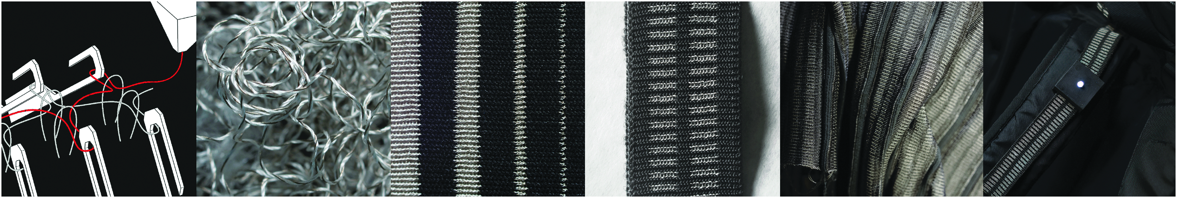
Left to right: interlocking structure with two-bed machine knitting; close view of conductive yarn; conductivity test knit sample with varying width; belt rheostat; mass produced knitted belt rheostat; belt light application.
While 3D printing conductive materials have been well explored, this work seeks to bring the machine knitting process closer to additive manufacturing design. With other responsive yarns, we envision that some of our knit designs can be adapted for not only creating sensors but also actuators and displays on a fabric for the future of human–material interaction design.
Related Works
Fabricating E-textile in HCI
The exploration of integrating electronics into textile has a long history in HCI.11,13,14 Researchers have been investigating methods of embedding sensors and actuators in fabric to create tangible user interfaces,15,16 expressive art work, 17 and encourage social interaction. 18 In general, the fabrication method can be divided into two categories: extrinsic (such as coating or laminating)7,11,19,20 and intrinsic (such as embroidery, weaving, or knitting)21,22 modification. Buechley and Eisenberg use lamination to attach conductive fabric with nonconductive ones. Atalay et al. composite dielectric silicone with fabric to create a fabric sensor. On the intrinsic modification side, Project Jacquard 4 thoroughly studied the integration of conductive yarn with fabric to create a capacitive sensor from the yarn to garment.
This work builds on prior works and explores digital knitting as a scalable fabrication process to create tunable sensors. With this method, the electrical property of the knitted fabric can be controlled at the stitch level.
Electronic craft with knitting
Knitting has been part of human culture for thousands of years. Many hobbyists, craftsmen, and artists have explored knitting with conductive materials, and use it as a sensor. Kurbak 23 has shown several works of knitting antenna and capacitors with copper wires. Hannah Perner-Wilson documented some of her knitted stretch sensors on instructables. Stitching World 24 also showcased some knitted capacitors. Our work introduces multiple knit designs and how they form resistive and capacitive sensors. We also report the performance of those sensors.
Machine Knitting
The textiles we encounter every day are mostly formed by either weaving or knitting. Compared with weaving, which uses a “yarn over/under yarn” structure, knitting forms a “loops through loops” structure. Woven textile is a collection of multiple yarns, while knitted textile can be formed with one single yarn (Fig. 3). The unique architecture of knitting allows one to create 2.5D or 3D geometries by varying stitches during knitting.

Digital machine knitting is a programmable and automated process of forming interlocked loops from single or multiple threads of yarn. Unlike hand knitting, that uses two (mostly) long sticks to form and hold the loops, machine knitting utilizes an array of hooks, called needles, to perform the task. The yarn enters the machine from a cone, passing through a tensioning device and a yarn carrier on its way into the knit object. One knitting machine can have multiple yarn carriers that can be used in one knitting program. Yarn carriers move laterally by the machine head, positioning new yarn when needed. As the yarn is positioned, the needles rise up to grab the yarn to form new loops. With machine knitting, it is possible to knit with multiple yarns in parallel or sequential order (Fig. 4). For more details of how machine knitting works, McCann et al. 12 have given a thorough explanation. Other tutorials and introductions to machine knitting principles can also be found in Spencer 25 and Sadhan. 26 Atef also created several animations 27 to demonstrate the needle movements during knitting.
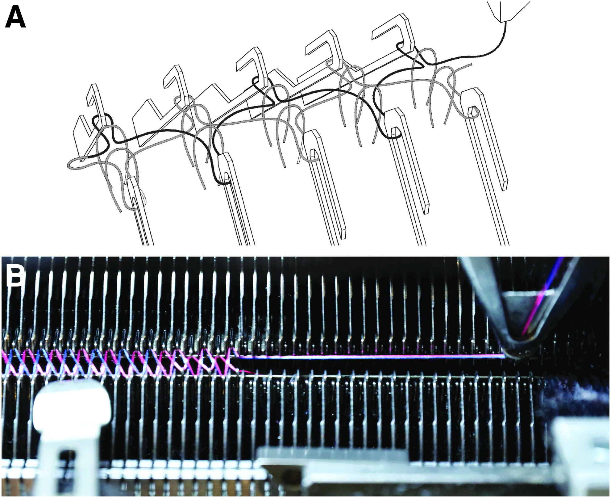
Machine knitting mechanism.
V-bed machine knitting
The machine we used in this article is from Matsuya (matsuya.com.cn). It is a two-bed or V-bed knitting machine. V-bed is one of the most standard designs in the knitting machine industry. It has two arrays of needles referred to as the back bed and front bed. Having two beds allows us to fabricate two layers of knitted fabric that can be connected at the end to form a tube shape, or at every other loop to form a single sheet. This gives us design freedom for forming different fabric shapes. In our case, we combined both tube and sheet geometry to form pockets for the sensor design (Fig. 5).
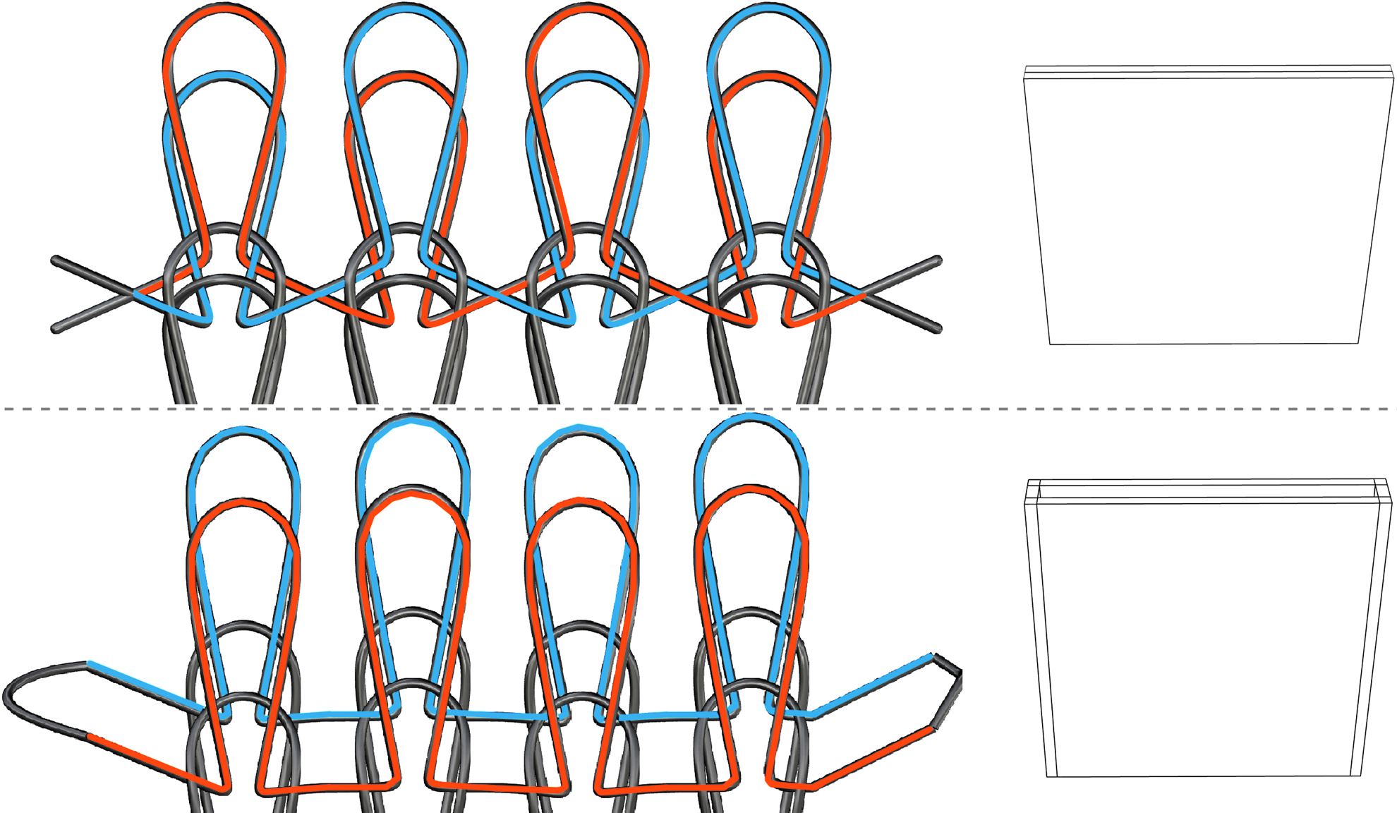
Knitting with both front and back beds. Top: interlocked knitting structure, bottom: tube-shape knitting structure.
Knitting program
To give the knitting machine instructions on when and where to form loops, we need to use a special design software that comes with the machine. This environment is not universal to every knitting machine, but the principles of the interface can be applied to other brands.
As Figure 6 shows, the design software is divided into two grid-based areas. On the left side, the user can design the overall shape of the knit piece and specify a knit operation at each x and y position by giving each grid a color. Each color represents a different knit operation. These operations include knit, tuck, transfer, skip, and so on. Since the machine has two beds, most of the operations are doubled for the front and back bed. For details on the knit operation color code, Matsuya offers instruction online.
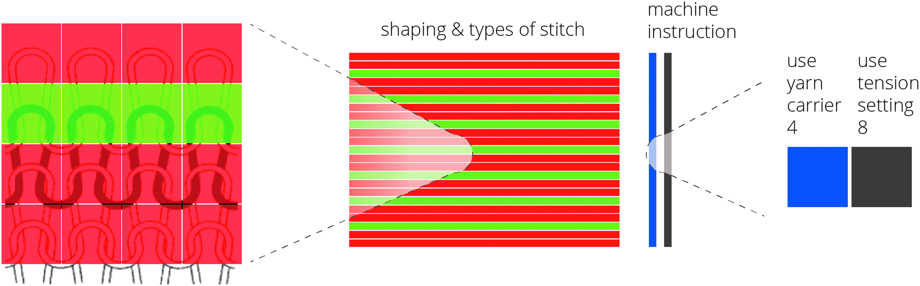
Principles of knit design program.
On the right side of Figure 6, the user can give more detailed machine instructions for each line of knit by also color coding the grid. Each color represents a numeric index in the machine parameter space, which later can be specified on the machine. Those parameters include which yarn carrier is used for each line, the knitting speed, the stitch tension, and so on.
Material Choices for Sensor Design
In electronics, it is possible to create a variety of components by simply controlling the geometry of conductive and dielectric material. In this work, we extend this method into the realm of machine knitting to achieve tunable knit capacitors and resistors that enable a subset of sensing capabilities useful for interaction design.
Conductive yarn
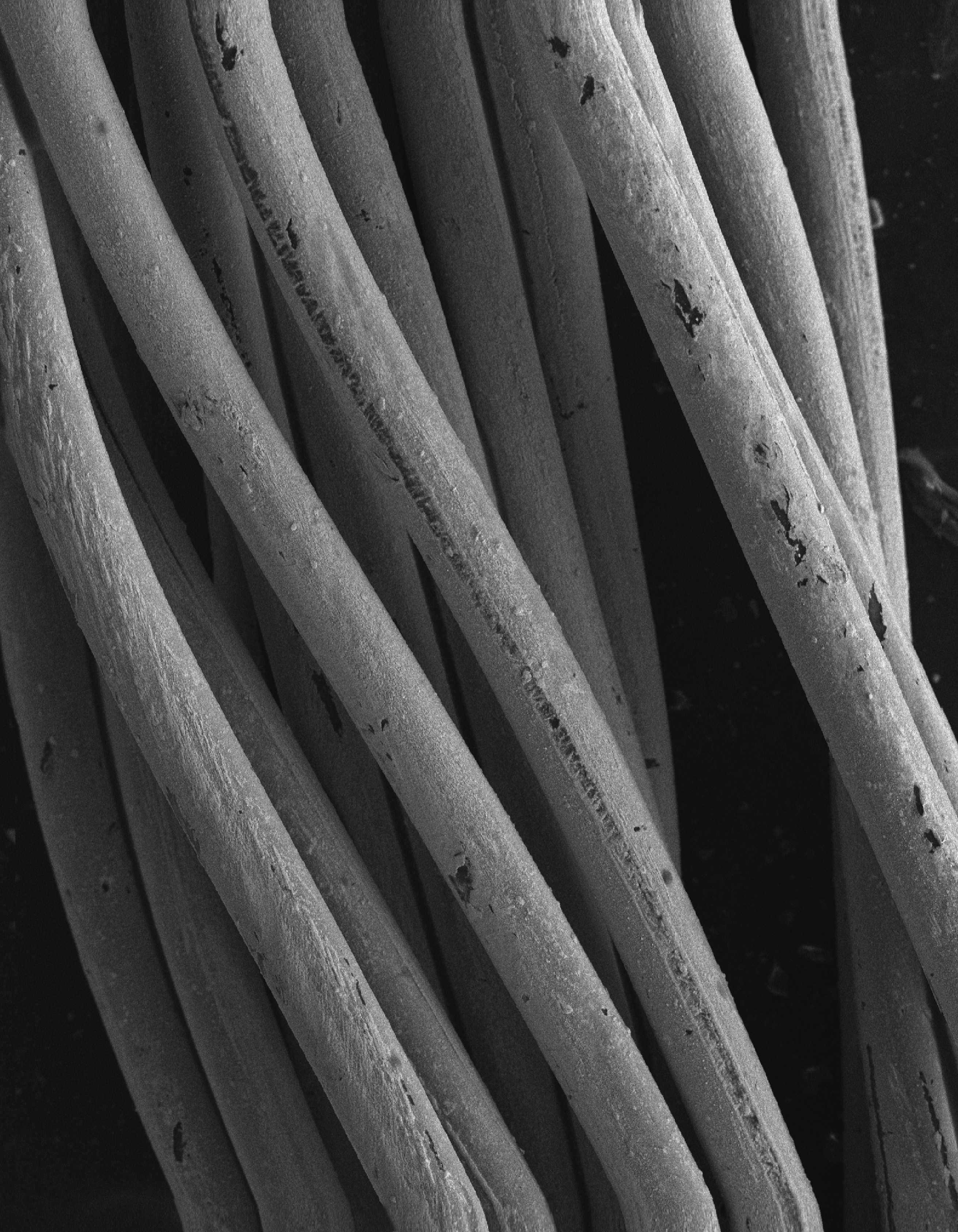
To build a house, we need bricks. To form a textile resistor, we need conductive yarn. As Project Jacquard has shown, there are multiple types of conductive yarn structures available on the market. We chose to use a yarn (sourced from Alibaba.com) that has a silverized set of fibers twisted together with nonconductive yarn. The yarn was chosen for its good balance between conductivity and resistance (1 ohms/mm) since we are forming resistors among other components. On close inspection of the conductive yarn fibers under scanning electron microscopy (Fig. 7), we found the fibers comprised a dielectric core with a thin film of silver nanoparticles on the surface ranging from 20 to 200 nm in size. Unlike the common metallic core yarn, which may compromise the knit conductivity if broken, the fibers coated with silver are ideal for our purposes as they readily make good electric contact with one another inside the knit structure while maintaining their structural and electrical integrity.
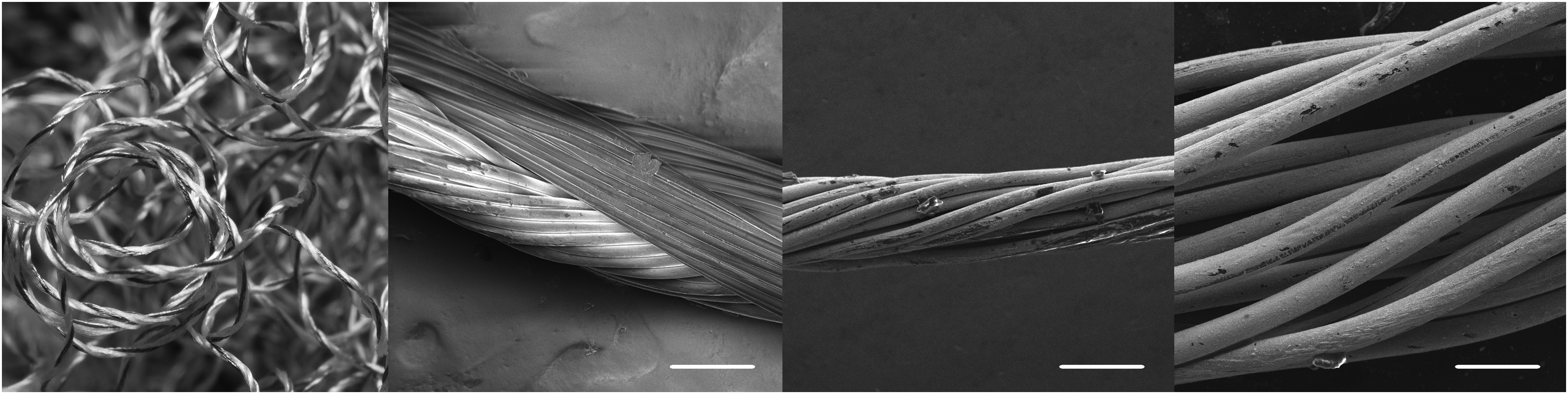
From right to left: photograph of conductive yarn, scanning electron micrographs with scale bars of 100, 100, and 20 μm, respectively.
Controlling conductivity with geometry
With a good conductive yarn at hand, we set out to characterize how the knit geometry affects bulk properties. To achieve this, we knitted an array of test samples where we varied the number of loops in each dimension to generate wires with varying length and width. We found the resistance to increase linearly with length and decrease inversely with width (Fig. 8). In addition, this loop-dependent behavior remained consistent for the three knit patterns we tested: jersey, interlocking, and ribbed.
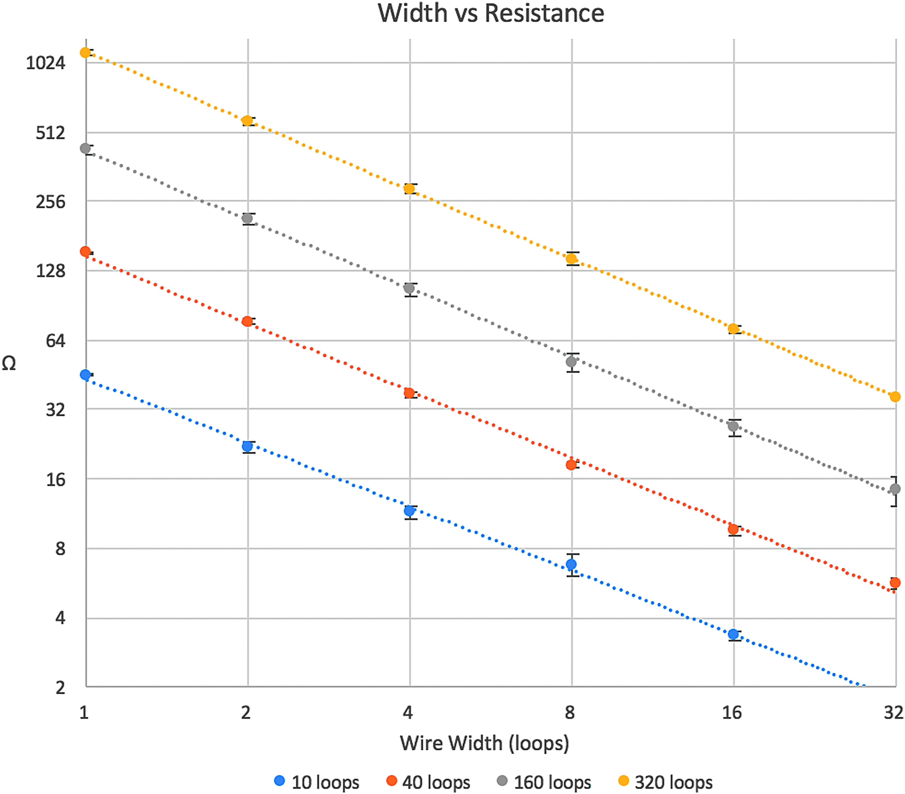
Log base 2 graph describing resistance in relation to loop length and width.
The equation above was found to describe the relationship between the loop number in length L and width W to the total resistance of the structure. The constant 2.63 was calculated based on Figure 8. Given a certain type of conductive yarn, this constant may vary based on the stitch tension, as it changes the contacting area among the loops. In our experiment, we used only one type of conductive yarn and one tension setting to keep the results consistent.
Controlling elasticity
Compared with weaving, a knitted fabric can be elastic even if the yarn is not. This is due to the “loops through loops” fabric architecture that behaves somewhat like a spring. In the case of designing resistors, this is not desirable as we want our resistor to maintain its value. This is solved by introducing bonding yarn in the knitting process.
Bonding yarn is typically a thermoplastic polyurethane (TPU) thread that melts at temperatures between 45°C and 160°C (available at www.emsgriltech.com). It has been widely used in the knitting industry to create nonelastic textiles (knitted shoes, bags, etc). We knit the bonding yarn with other fibrous yarns (including the conductive yarn) at the same time. When leaving the machine, the knit remains elastic. After ironing for a few seconds, the bonding yarn melts yielding a flexible textile without elasticity. With this method, we can knit conductive yarns to form resistors that have a stable performance.
In other cases, we would like to be able to control the elasticity of the knitted fabric. This can be done by knitting with spandex yarn. The stitch tension is tuned to knit tight when knitting with spandex so that the elasticity of the yarn is more dominant than that formed by its loops. We used spandex (available at supremecorporation.com) to create our stretch sensor in this article.
With these choices in yarn, we set out to explore different knitting architectures that can be used as sensing mechanisms for interaction design.
Machine parameters
The industrial knitting machines allow you to tune parameters such as tension, take-down speed, and cam speed. Those parameters are usually given course by course. While all of the parameters contribute to the final quality of a knit, we found that tension is the most important for knitting conductive yarn. In machine knitting, tension refers to the amount of distance that each needle pulls down after a knitting movement. This controls the tightness of the stitches. The higher the number is, the looser the stitches will be, as the needles make bigger loops by moving further down. When knitting with conductive yarn, this parameter influences not only the knit dimension but also conductivity, as it changes the contacting area of the conductive yarn.
The unit of tension might vary among brands. For Matsuya, the unit is per steps of the stepper motor that controls the moving distance of the needles. In our project, we used the same tension setting (300 on the Matsuya machine) for all knits with conductive yarn to keep the results coherent. The tension for other yarns (polyester and spandex) varies to create different tightness based on the type of sensors we are trying to make.
Rheostats
Mechanism
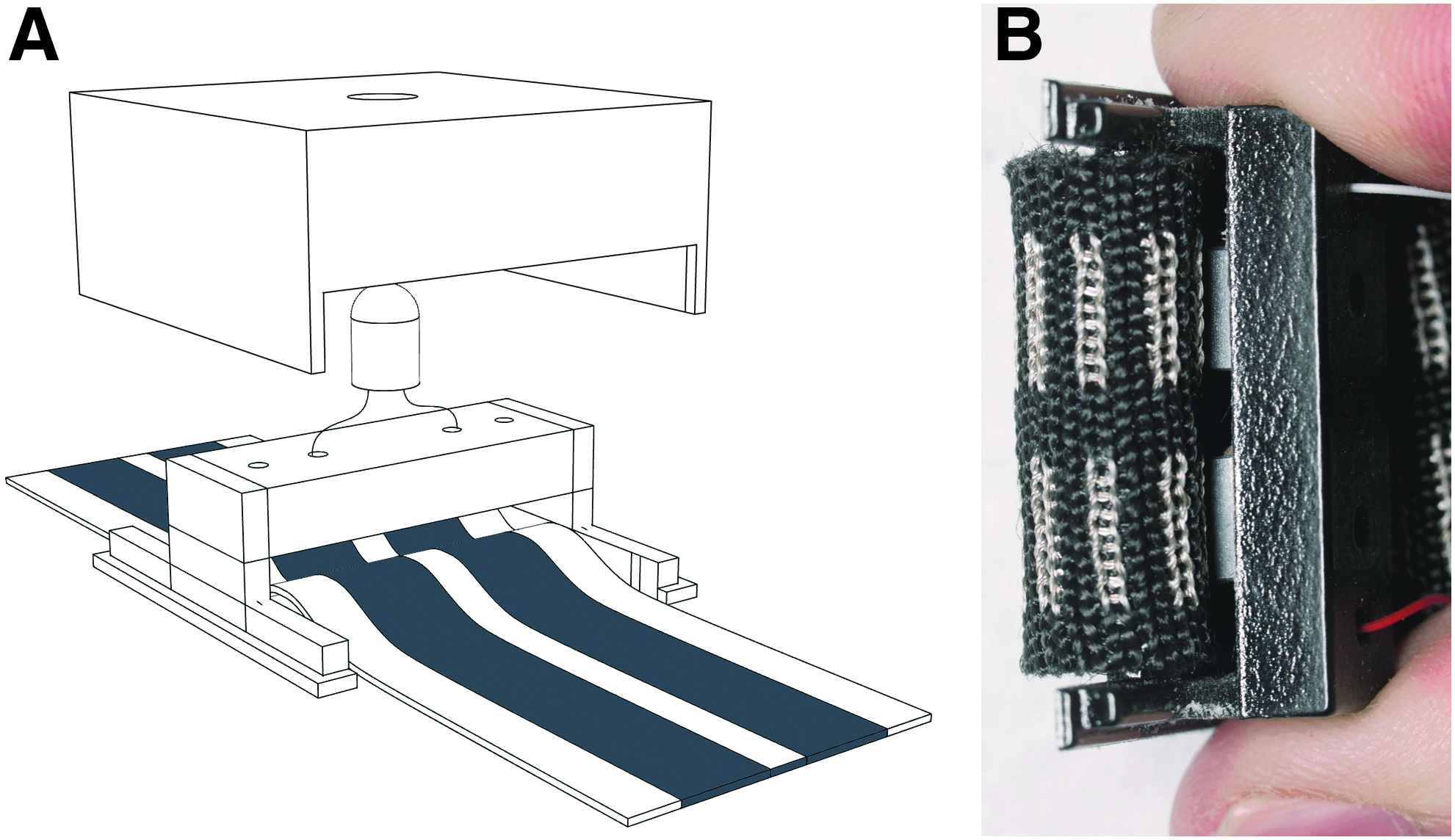
We created two types of sliding rheostats based on a change in resistance. The principle behind this is to create two conductive strips on the fabric with conductive yarn, which can be selectively shorted to change the resistance based on the path length of the circuit. The first design is a belt-like textile that is knitted with polyester (Fig. 9A). Two strips of the conductive knit are added in parallel on the belt and the resistance can be dynamically varied by shorting the two conductive strips with a metallic buckle. We can also give a predefined range of resistances by varying how many lines of loops the conductive yarn forms. The second design follows the same principle, except the shorting mechanism is provided by an embedded neodymium magnet (Fig. 9D). Instead of using two beds to form a single sheet of fabric, we knit a spandex pocket that can fit one ball magnet inside. The user can change the resistance by moving the magnet with a magnetic token. The benefit of this design is that the value of the resistance remains even if the token is removed.

Knit design
Figure 9B and E illustrates the knit program we made to create such structures. For both designs, we introduced the yarn carrier with conductive yarn during the knit. Figure 9B forms a pocket as it knits on the back and front bed sequentially. Figure 9E forms an interlocking structure like Figure 5B, as it knits on the back and front bed alternatively. Notice that we gave different colors to the tension setting between conductive yarn and the other yarn. On the knitting machine, they are set to 300 and 360, respectively. The goal is to make sure the conductive loops are tightly connected.
Fabrication
The two rheostats are fabricated with 1 thread of 400 denier ultrahigh-molecular-weight polyester (sourced from Alibaba.com), 1 thread of 450 denier silver-coated conductive yarn, and 1 thread of 150 denier TPU yarn. We then carefully ironed the final knit product to melt the TPU at ∼100°C.
Characterization
The rheostats follow the rules dictated by the equation derived from Figure 10. Using this, we were able to predictably knit structures with a desired resistance that changes linearly with length.
Stretch Sensor
Mechanism
While a knit piece can be somewhat elastic due to the interlocking loop structure, the fabric does not restore to its original shape quickly after stretching. To achieve a rapidly restoring fabric, we used spandex yarn to create an elastic fabric with low hysteresis. The knitted spandex fabric acts as a mechanical base on top of which we knit multiple pockets with conductive yarn. The pockets were carefully designed so that they overlap with each other when laid flat, resulting in conductive pleats. As the fabric is stretched, these pleats shear away from one another reducing the amount of surface area they have in contact, resulting in an increase in resistance. After releasing the piece, the sensor rapidly returns to its original form thanks to the underlying spandex (Fig. 9G).
Knit design
Figure 9H explains the knit design we made for the stretch sensor. The sensor is made with two-bed knitting, with the front bed knitting the conductive pocket and the back bed knitting the spandex substrate. As we are knitting the front bed, the loops on the back bed are held still by the needles. This way we can form a pocket after the yarn is transferred from the front to the back bed.
Fabrication
The two rheostats are fabricated with 4 threads of 150 denier polyester (available at supremecorporation.com), 1 thread of 400 denier spandex yarn, and 1 thread of silver-coated conductive yarn. After being knit from the machine, we carefully ironed the knit to flatten the conductive pockets into flaps at ∼100°C.
Characterization
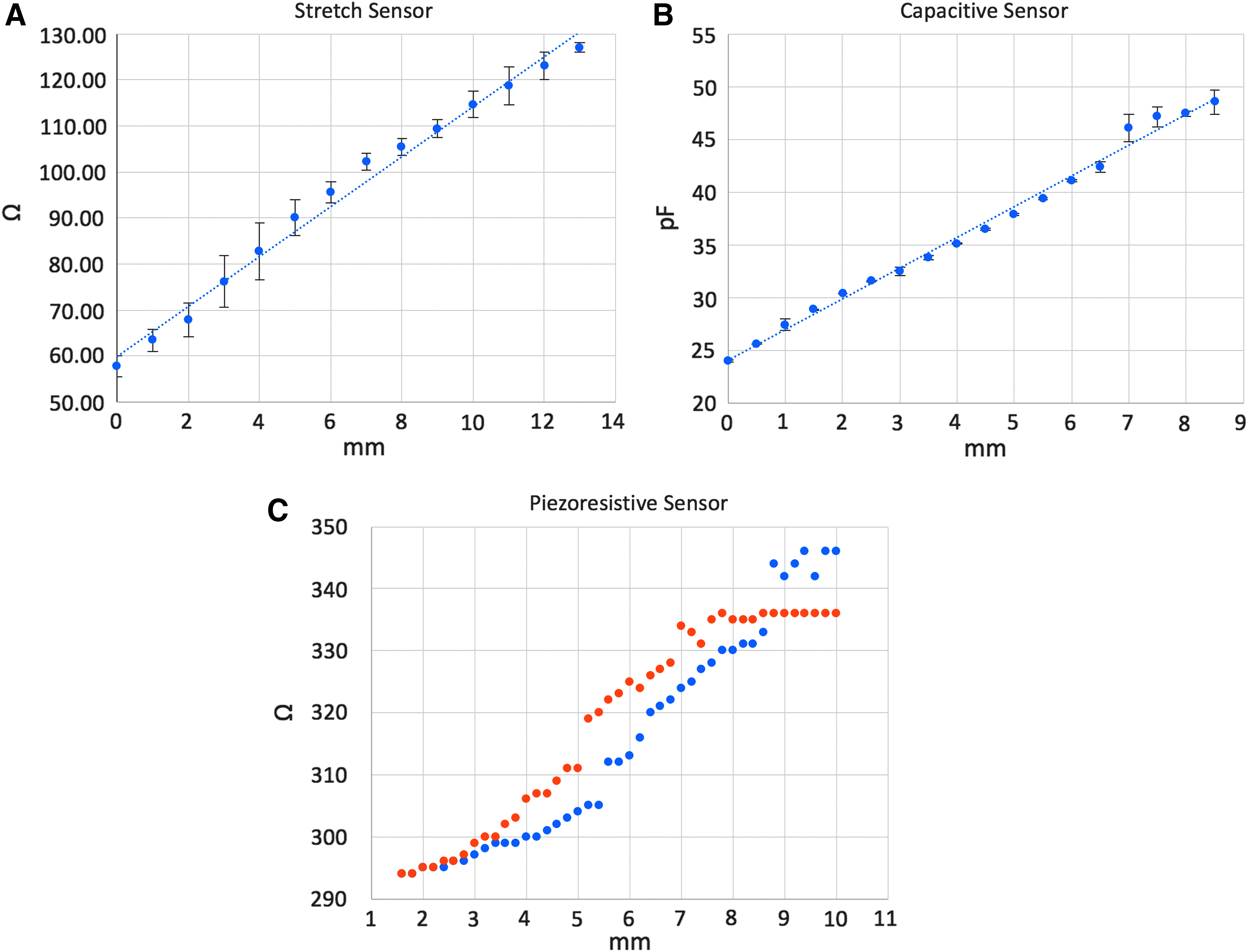
The stretch sensor was characterized by placing it in an ADMET universal testing machine configured for fabric tensile testing. The sensor was clamped on both sides and pulled until barely taut. Alligator clips connecting to a multimeter were attached to the top and bottom conductive panels of the sensor. The machine then pulled the fabric in 1 mm increments while resistance was noted. Above a distance of 13 mm, data were not collected as the conductive panels were fully separated at this point and measurements remained static. It was found that the stretch sensor behaved linearly with distance. This is expected as the total resistance is determined by the amount of overlap between the conductive panels. In addition, no hysteresis was observed in this setup.
Distance/Pressure Sensors
Mechanism
Knitting with conductive yarn provides the capability to create capacitive electrodes for sensing purposes. These plates can function both as touch inputs and more generally as distance sensors. We extend this capability to allow for the creation of a pressure sensor by injecting yarn into a knit pocket. One side of the pocket is knitted with the conductive yarn as the plate, while the other is nonconductive polyester. As we knit the top plate in a dome shape (Fig. 9J), the geometry provides a smooth change of capacitance as a finger presses down. Since the injected yarn can provide physical resistance, we stipulate that it is possible to sense pressure given a stress versus strain curve for the substrate, where stress can be deduced by the strain (or displacement) of the pocket, as measured by capacitance.
For an accurate digital measurement of the capacitance, we used the Teensy 3.2, which includes the 32-bit ARM-Cortex M4 that features nine capacitive touch inputs, all handled and conditioned inside their touch sensor interface (TSI) chip. 28
Knit design
Figure 9K explains the knit design we made for the pressure sensor. With two bed knitting, we can create a dome-shaped pocket by knitting extra lines on the front bed while keeping the back bed held. Although it looks like the front knit separates the whole piece into two parts in the knit program, those edges connect back with each other after the pocket lines are done.
Fabrication
Our pressure sensor is fabricated with 4 threads of 150 denier polyester and 1 thread of silver-coated conductive yarn. To inflate the pocket for the pressing interaction, we injected 2 continuous threads of 150 denier polyester in the pocket. The injection was done using a modified air brush with a needle tip. We filled the pocket until polyester could no longer be injected. After that, we carefully trimmed the thread leads for better visual appearances.
Characterization
To test and characterize our pressure sensor, we developed the following experiment. The top knitted electrode is connected to the Teensy 3.2 capacitive touch input via alligator clips and then placed under a linear actuator with a metal top piece that functions as a finger analog. The metal piece is moved via a linear actuator in increments of 500 μm beginning from first contact with the sensor. The capacitance measured on the Teensy's serial monitor is logged and graphed as shown in Figure 11B.
A tablecloth as a lighting lab controller.
Piezoresistive approach
As another method to achieve touch and pressure sensing, we explored a means of creating a piezoresistive substrate using yarn. It is well known that piezoresistive sensors have nanoscale features that percolate as pressure is applied to the substrate. We extrapolated this mechanism on a macroscopic scale by thinking of the conductive yarn as a network of conductive nodes that can be increased by pressure-induced percolation. With this insight, we tested a method of injecting a mixture of conductive yarn mixed with dielectric yarns into pockets. The machine knitting allowed us to create conductive electrodes on both sides of the pocket with which the resistance could be measured. We tested this prototype by stepping a linear actuator 100 μm and reading the resistance at each position. We performed a single set of measurements for both pressing and releasing (Fig. 10C). It was found that resistance changed reliably with displacement but also exhibited substantial hysteresis. As with the capacitive sensor, we stipulate that by correlating the displacement with stress it is possible to create a pressure sensor.
Applications
Textiles are widely used in our everyday life, from the things we wear to the things we use. As mentioned in the introduction, knitting can create large textile sensors without restriction on the number of courses. The fabricated pieces are also easy to connect with other textile accessories such as a buckle or zipper. It broadens the design applications of additive manufacturing. To showcase that, we designed three application prototypes of the knit textile sensors.
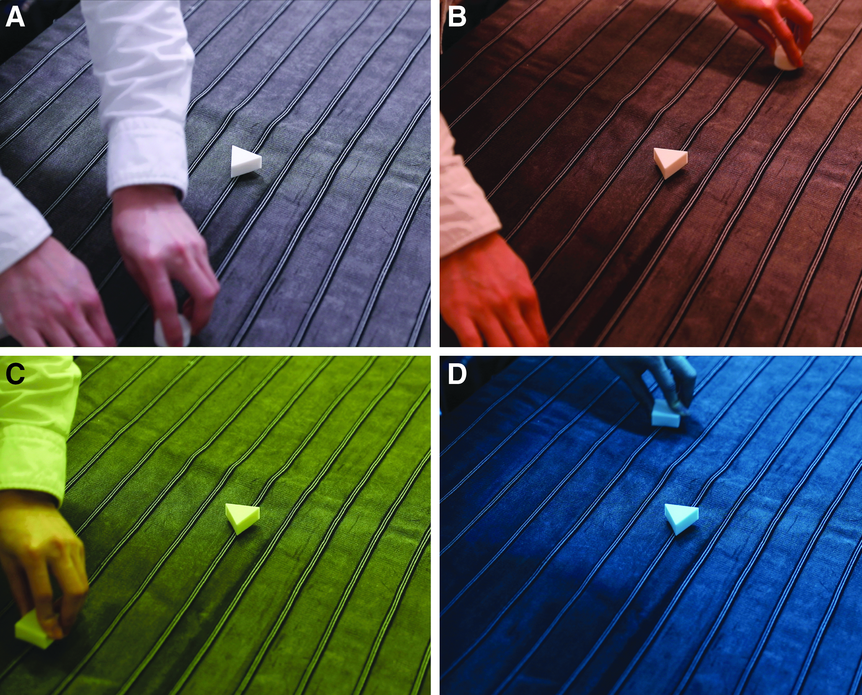
Lighting control tablecloth
Embedding new sensing modalities into household/indoor objects to control aspects of the environment has been a topic of research in HCI for decades. Most notably, Project Jacquard's vision of interactive textiles in connected spaces. To demonstrate the use of our knitted rheostats in an interactive indoor environment, we designed and manufactured a large 12-channel, 80 by 120 cm

Diagram of the tablecloth control system. The six channels are connected through voltage dividers to the analog pins of a microcontroller and then to a computer before being broadcasted to the lighting lab's server via its WebSocket API.
Safety light belt
Belts are one of the most common textiles we use daily. Together with a buckle, the length of a belt can be easily adjusted for apparel, backpacks, and so on. Inspired by this interaction, we knitted a resistive belt that was later sewn onto a backpack (Fig. 13). The belt travels through an LED light module and acts as a variable resistor to dim the light. The LED, battery, and the voltage dividing resistor are integrated inside a 3D-printed case, whose internal structure can fix the position on the belt like a normal buckle (Fig. 14). This application explores the direct use of our knitted mechanisms with simple analog circuits. Further features could be added into this model using digital electronics, for instance, to allow various light-based notifications, change of color, and flickering rate and patterns, to name a few.
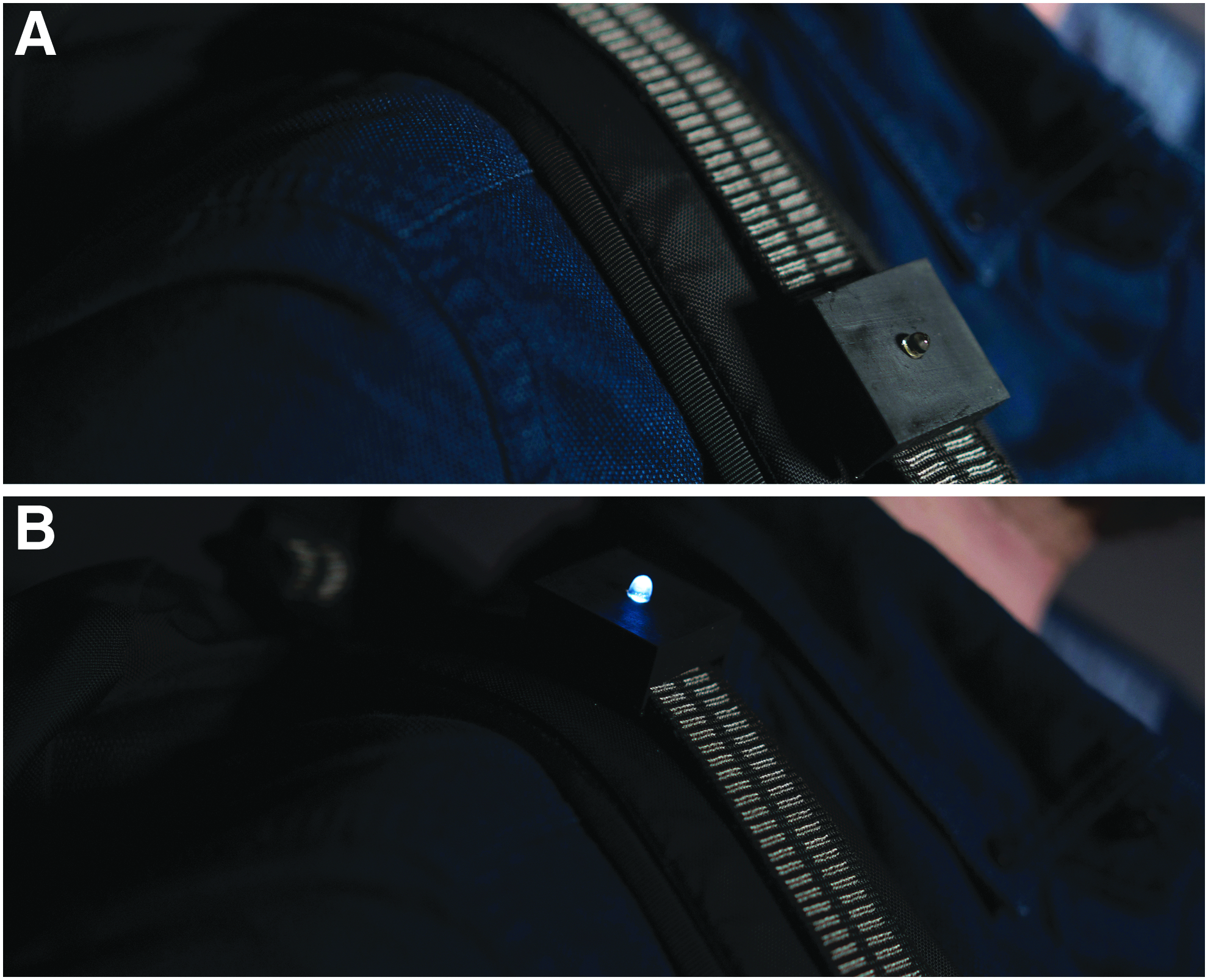
Customized belt rheostat sewn onto a backpack with a 3D-printed enclosure that covers the buckle, and a voltage divider circuit that changes the brightness of an LED; (
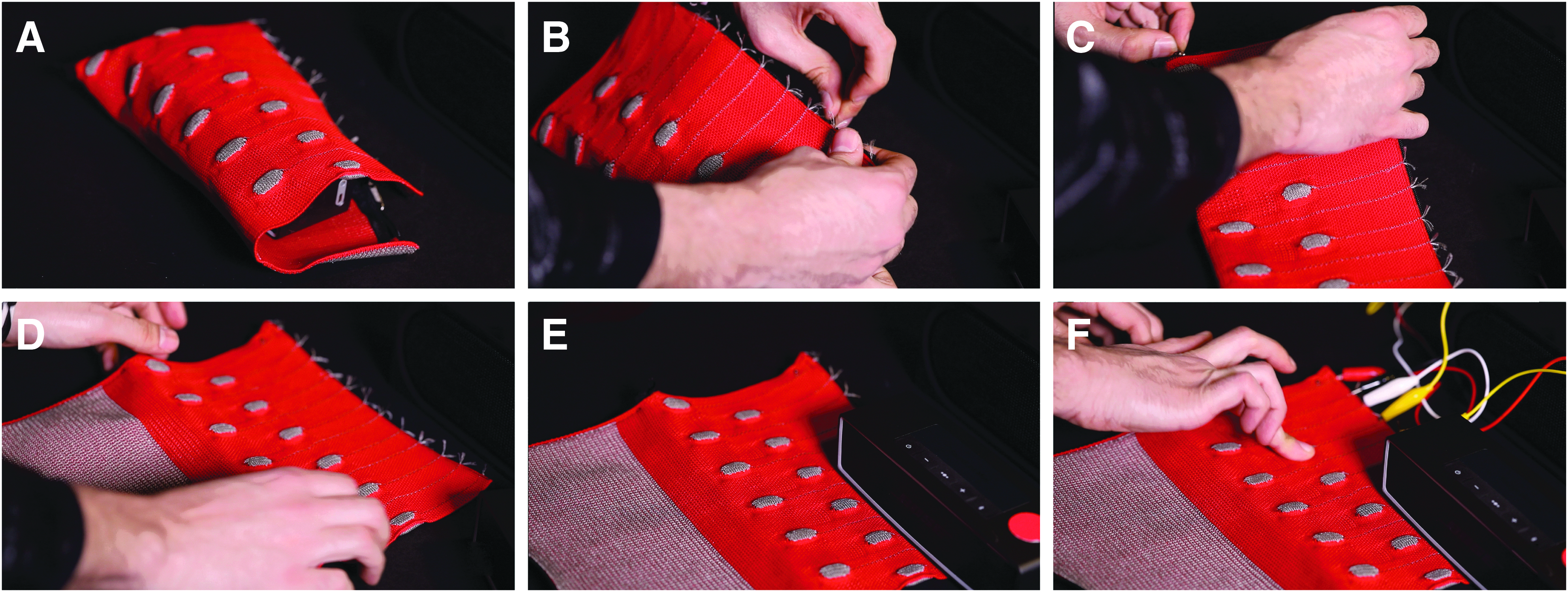
Handbag instrument
One advantage of using digital knitting machines to create flexible and stretchable control interfaces lies within the accuracy, reproducibility, and ease with which the interfaces can be manufactured. A variety of e-textile musical instruments or controllers were explored either as academic research or as consumer products. 30 The handbag instrument relies on the capacitive sensing mechanisms. This small bag is designed to encapsulate a modified battery-powered speaker (Bose SoundLink Mini). From a user interaction's perspective, this dual interface is used as a protective storage bag for a speaker, as well as a musical instrument/controller when unzipped and flattened onto a surface. The sound of this instrument is mapped to different parameters. The touch sensors are mapped to trigger percussive samples, while the pressure is mapped to the sample rate. Adding a record function on the last key turns this interface into a fun and engaging drum machine. The sound of this instrument is synthesized using the Mozzi library, 31 running on the Teensy 3.2, due to its built-in capacitive touch inputs and its 12-bit digital analog converter (DAC) allowing richer sounds (Figs. 15, 16).
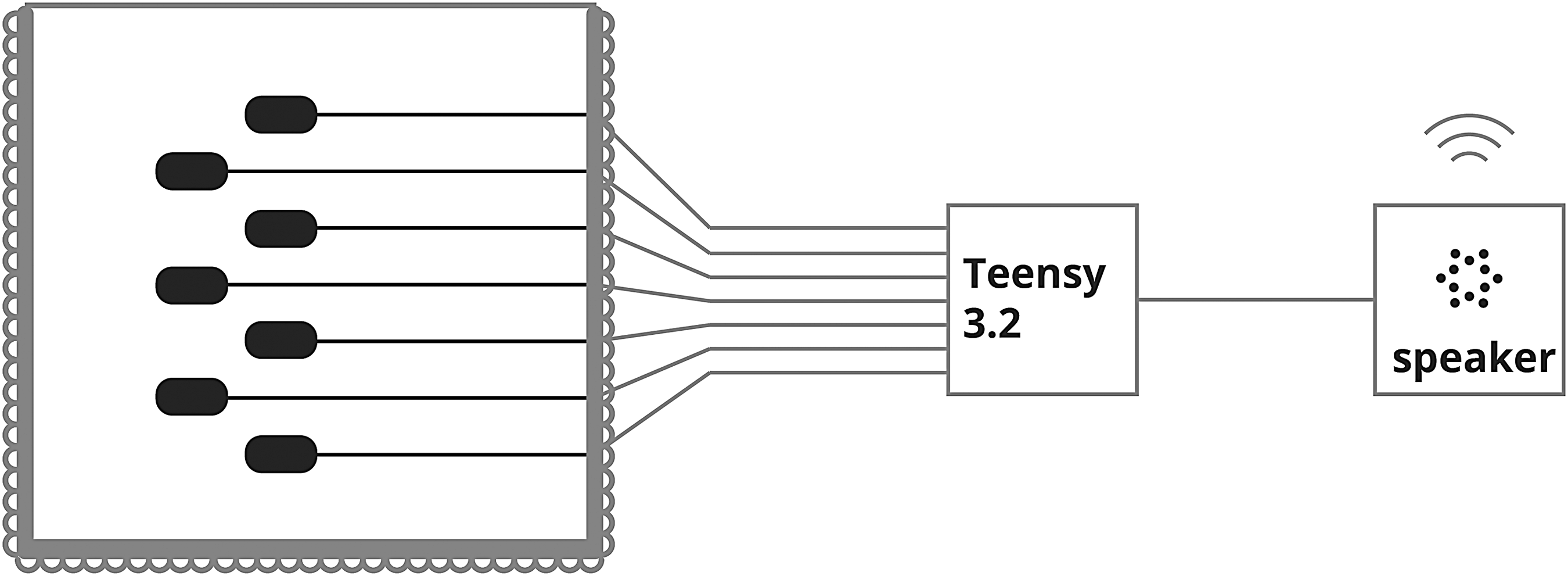
A diagram showing the implementation of the handbag instrument; the knitted electrodes from the instrument connect to the Teensy's capacitive sensing input pins; and the audio output comes out of the Teensy's internal DAC on pin 14. DAC, digital analog converter.
Limitation and future works
Knitting is one of the oldest textile fabrication methods in human culture. Throughout history, knitting stitch patterns and structures have been mostly used for aesthetics and structural support. Our work utilizes those patterns and structures to produce unique textile sensors.
Due to the nature of the knitting machine, our approach of knitting sensors is limited in terms of possible knit geometries. For example, it is difficult to knit the conductive yarn vertically. Therefore, it is difficult to create a network of connected sensors within one knit. Since we are using a two-bed knitting machine, our sensor is exposed outside rather than embedded in the inner layer of a knit. This could be resolved by using a four-bed knitting machine. In our experience, machine knitting is also a complex craft that requires years of expertise to smoothly implement a design to machine code. Compared with the direct-ink writing method, it is less intuitive for sensor design. However, machine knitting is also a very matured technology. With the development of high-quality conductive fiber and computational knitting geometries, we believe knitting could be the most promising method to integrate sensors into a whole garment or furniture design. In the future, we would also like to experiment the following ideas.
Interfacing knits and electronics
E-textile has always been at the center of discussion for future ubiquitous computing. As this article focuses on the structural design of knitted textiles with conductive yarn to form textile sensors, we also realize that a better design and fabrication process of interfacing textile and other electronic components, such as batteries and microcontrollers, is very much crucial. In the future, we would like to explore the possibility of knitting “sockets” that allow an easy connection between wire and yarn. We would also like to explore using existing textile accessories, such as a buckle, press button, or conductive Velcro, as a nonobtrusive connection between fabric and electronics.
Integrated design
As machine knitting is a versatile fabrication process to make 2D or 3D textiles, it opens a more integrated design space for designers to incorporate sensors in a finished product without much postprocess, such as sewing or laminating. For example, we can knit an entire backpack for our safety belt light application to make the design more integrated. We envision that the future knit design should not only be about shapes but also about properties such as conductivity and capacity. A software interface should be designed to give material electrical property estimation based on a given design.
Beyond sensing
Last, we would like to adapt our structural design methodology in knitting to other functional yarns such as heat-responsive, thermal chromic yarns to create interactive textiles at the stitch/loop level. This would allow an interaction designer to not only design an interaction but also “architect” a material.
Conclusion
In this article, we reported three classes of textile sensors exploiting resistive, piezoresistive, and capacitive properties of various conductive yarn geometries enabled by digital knitting. Digital knitting is a highly programmable manufacturing process that has been utilized to produce apparel, accessories, and footwear. By carefully designing the knit structure with conductive and dielectric yarns, we found that the resistance of knitted fabric can be programmatically controlled. We also present applications that demonstrate how knitted sensors can be used in the home and in wearable devices.
Footnotes
Acknowledgments
This work was supported by MIT Media Lab Consortia Funding. We also thank Zhiyu Yu, Angela Chang, Jordi Montaner, and Andy Su from K-Tech for providing machine and knitting knowledge during the project.
Author Disclosure Statement
No competing financial interests exist.