
Abstract
Three-dimensional (3D) printing is a powerful rapid manufacturing technology with wide applicability in scientific research, in industry, and for the home hobbyist. A popular 3D printing discipline known as fused deposition modeling (FDM) has several shortcomings, including stairstepping in the approximation of curves, anisotropy in physical properties, and the need for support material in models with large overhangs and severe angles. These limitations are especially concerning in 3D bioprinting of tissue constructs that contain voids, including a host of tubular biological structures such as vasculature, intestine, respiratory tissue, and long bone. The use of sacrificial support material can lead to excessive printing time, while its exclusion may lead to mid-print or postprint tissue collapse. Additive-lathe 3D printing technology is an emerging discipline in the field of additive manufacturing and offers a unique method for FDM printing that promises to circumvent some of these inadequacies while adding value as an alternative printing technique. The technology has seen use in several fields in recent years, yet researchers making gains in disparate fields appear to have not fully realized each other's advancements. This review aims to summarize the history and current state of additive-lathe 3D printing, comparing the hardware and software approaches of each embodiment, as well as their output. The review will go on to provide interdisciplinary insight into the utility, limitations, and potential future trends in this growing additive manufacturing technology.
Introduction
When Adrian Bowyer, founder of the RepRap project, released designs for the version I “Darwin” in May 2007, a worldwide community coalesced around the concept of collaboratively developed, rapidly-reproducing replicators. In a review of the to-date results of the project in 2011, Jones et al. noted that the lowest cost, nonopen-source consumer three-dimensional (3D) printer was just under U.S. $10,000 at the time of writing, which was cost prohibitive for the average user. 1 At the reduced price point that these open-source 3D printers commanded, this project in conjunction with the Fab@Home Model 1 syringe extrusion-based 3D printer first released in 2006 2 sparked the home 3D printing revolution. With thousands of people collectively working on the hardware, software, electronics, and printing parameters for personal additive manufacturing and sharing their work with the world, progress in the field was made at an accelerated rate, driving down the cost of high-quality additive manufacturing machines 20 fold in under a decade. This technology was bred in an open-source and collaborative environment to the benefit of all users, and the current field of commercially available desktop 3D printers was partially built on the foundation of this open-source technological boom.
Since Thomas Boland filed the first 3D bioprinting-specific patent application in 2003, 3 reimaging an inkjet printer cartridge for printing cell suspensions in a layer-wise manner, 3D bioprinting has benefited greatly from the advancements of other areas of abiotic layerwise deposition of material. The increasing interdisciplinary crossover between desktop fused deposition modeling (FDM) and bioprinting, such as the use of poly(lactic acid) (PLA)-based 3D printing in biomedical applications for its biocompatibility and degradability,4–7 is evidence that an advancement in one field will drive advancement in the other. With open-source and off-the-shelf positioning systems and software options becoming widely available, researchers could focus on deposition systems uniquely capable for their purposes. Where once systems required cost-prohibitive motion controllers with price points of several 1000 dollars, 8 three-axis printing machines can now be controlled using low-cost microcontrollers and stepper motor drivers. At one time, positioning systems were limited to expensive linear motion stages with unnecessarily high resolutions with respect to the course size of deposited material 9 ; now, scores of low-cost, open-source designs and off-the-shelf products exist. Comprehensive reviews of other current bioprinting and additive manufacturing technology paradigms can be found elsewhere and will not be covered in detail in this review.10,11
Current limitations of FDM 3D printing
There exists no single 3D printing modality able to serve the needs of every use case, each having their own inherent utility and associated considerations for usage. FDM 3D printing systems, although 1 of more than 10 categories of general and application-specific 3D printers available,12–14 are a popular choice by the home hobbyist.
The positioning systems of various FDM printer designs (Cartesian, delta, polar, etc.) may move differently within the build space, but each ensures that the tip of the extruder nozzle remains normal to the print surface. This is a necessity considering the intended use of the FDM printer: layered deposition of a stacked set of 2.5D contours orthogonal to a flat printing surface. Due to this layered deposition in a single direction, traditional FDM printing suffers from issues related to anisotropy. 15 Where printed part mechanical properties are of concern, the longitudinal strength—the strength of an unbroken trace/filament—has been found to differ from adhesive strength—the strength where discontinuous filaments merge together. Generally speaking, the longitudinal strength is the greater of the two, 16 posing a problem in applications where a load is placed on the component and increasing the likelihood of failure between laminations. There is therefore a fundamental issue with traditional FDM printing, in that regardless of model complexity, the finished part will rely on the adhesive strength between layers in the direction of printing. For printed parts that undergo some physical load, anisotropy associated with the weakness of laminations in the direction of print must be considered.
Surface skin appearance and the de-facto bottom surface in FDM 3D printing depend on the design of the model. In practice, the greater surface area of the first layer that is in contact with the build surface, the better hedge against part warp. Printing a curved shape onto a flat build surface without special consideration could lead to an unintentional flat bottom surface. 17 Certain geometries can require substantial support material to be co-printed to contend with large overhanging features, while other models cannot be printed with this technique at all.
Curvature in the model is reproduced by different means between single contours in the XY plane and across contours in the Z direction. Curvature in the XY plane is approximated by many-sided polygons, while curves in the Z direction are approximated by offset layers. In this way, models with drastic curvature along the build direction can often suffer from obvious stairstepping. Stairstepping can be mitigated by utilizing thinner slices or by implementing an adaptive slicing protocol such as the one suggested by Minetto et al. 18
A typical hot end or paste extruder utilizes a nozzle with a hole of circular cross section. The cross section of a filament printed from such a nozzle will depend on the distance between the nozzle and the print surface below. For proper layer adhesion, the layer height setting should not exceed the nozzle hole diameter. In this typical case the resulting printed trace will have a cross section of a circle compressed between flat surfaces above and below, resulting in a rectangular geometry with semicircular ends. In the case of a mid-air extrusion, for bridging purposes, the cross section will be circular. If settings are not calibrated appropriately, printed traces may suffer from over- or under-extrusion, causing adjacent traces to merge in a nonideal manner. The cross section of the printed trace is an unavoidable consequence of the extrusion method and results in the outer and inner perimeters of printed closed-loop polygons taking on this shape. These unavoidable microstructures can affect the surface appearance of the printed part or may serve as inadvertent physical cues in 3D bioprinting constructs, 17 present regardless of intention.
Current limitations in 3D bioprinting
A confounding problem in 3D bioprinting is the collapse or deformation of structures due to weak mechanical properties of common biomaterials. 19 This can be especially problematic for constructs containing voids, particularly tubular biological structures. The use of sacrificial support materials has been employed successfully to print certain tissue constructs that include voids,20–23 yet the co-printing of sacrificial material can be tricky and time consuming in a paradigm much less forgiving than single-material desktop plastic printing. Utilizing traditional 3D bioprinting technology to produce constructs with an open cylindrical shape, such as nerve guide conduits or other cylindrical hydrogel matrices, necessitates printing the structure either horizontally or vertically onto a flat build surface.17,24 Without sacrificial support material, both of these methodologies are impractical with many published bioink formulations. The inherent compliance and high water content of some biomaterial result in the collapse of engineered tissues under their own weight or light load.19,25–27 For this reason, there can be limitations in the size and complexity of 3D printed constructs. In addition, due to the cross section of printed traces, using silicone or thick extruded bioink pastes leads to grooved patterns inside and outside of the construct. 17 These resulting microstructures may act as physical cues to cells which might or might not be intended or ideal.
Thermoreversible bioink formulations utilizing porcine gelatin or Pluronic F-127 are convenient as sacrificial materials in that they can be cleared from a construct with a brief temperature change.20–23 A horizontally-printed vessel-like structure can require both an outer encompassing support structure and support interior to the void, 28 and thus, the proportion of printing time and material to print the construct can be skewed heavily toward the support structure. When a co-printed sacrificial material is required, the complexity of the machine and associated software is increased to support this functionality. Unlike desktop 3D printer sacrificial materials, specifically designed for their compatibility with commonly used printer materials such as acrylonitrile butadiene styrene (ABS) and PLA, thermoreversible bioink may not co-print ideally or possess the ability to maintain long-term support with an application-specific scaffold material. 29 Bioprinted gelatin support structures liquefy and dissolve out of constructs at culture temperatures required to maintain long-term viability of mammalian cells, and Pluronic F-127 inks will dissolve in aqueous environments,9,20,21,29 traits which may or may not be ideal in a particular application. To address issues associated with co-printing support materials, and constructs deforming under their own weight, techniques for fabricating biostructures within support baths have been reported.30–33
Three-dimensional bioprinting may or may not include the printed deposition of living cells concurrent with scaffold material. If cells are printed along with the scaffold material, printing becomes time sensitive, as cells can begin to die outside of ideal culture conditions. In this case, it is imperative to design experiments that mitigate unnecessary printing complexity, duration, and postprocessing as much as possible.
When one considers the intricacies of attempting to print a structure such as a large blood vessel with multiple tunicae, traditional 3D printing modalities begin to appear less than ideal. The additive-lathe provides a methodology to build such structures radially outward one layer at a time, as opposed to the complex coordination required for the co-printing of biomaterials with unique properties, various cell types, and support structures.
Recently, with the above considerations in mind, 3D printing has been reimagined to better serve the creation of models with axially-oriented, trans-construct voids. An “additive-lathe” contrasts a traditional lathe in that its function is to progressively add layers radially outward from a rotating cylindrical mandrel, offering a host of benefits over both traditional FDM technology and subtractive lathing. With additive-lathe printing, nearly all functionality developed for traditional FDM printing can be ported over to the new technology, with certain modifications.
Necessity for additive-lathe 3D printing
While the home 3D printing hobbyist learns to recognize the limitations of traditional FDM 3D printing technology, designing around these shortcomings for parts such as propellers, impellers, wheels, augers, and a host of additional complex models without an obvious base to build from can be challenging. Co-printed material necessary to support drastic overhangs can often alter the surface quality of the finished part and increase overall printing time. Adoption of additive-lathe technology thus reduces the need to make substantive concessions dictated by the limitations of traditional FDM machines in certain applications. In addition, the technology may find use within the growing fields of complex curved/stretchable electronics 34 and soft robotics as well.
Traditional tissue engineering techniques have been used for years to create a wide variety of tubular constructs. 35 Traditional means of creating vascular stents, such as using the four-axis laser cutting technique, are industry standards. 36 FDA-approved nerve guide conduits and vascular stents produced with these techniques have been successful, but some possess concerning drawbacks.37,38 Researchers have demonstrated the promise of using 3D printing technology to replace these traditional techniques for patient-specific care. For example, 3D printed nerve regeneration guides offer the promise of facilitating the regrowth of severed proximal and distal nerve stumps. 17 Out of necessity, this work has been performed with traditional 3D printers, when these constructs would be very strong candidates for the use of the additive lathe. The technology could well be used for additional applications, such as in the additive manufacture of long bone, vertebra, intestine, urinary tract, esophagus, trachea, seamless tubular skin prints, and lymphatic vessels, among others with an axially-oriented void. For certain model designs and geometries, 39 the additive lathe could be used as an alternative fabrication methodology to provide better surface appearance and physical properties and print in less time while reducing or eliminating the need for support material.
In this interdisciplinary review, we first examine the intellectual and developmental timelines of additive-lathe 3D printing technology (Fig. 1). Although the field has limited sources to draw from, they are systematically dissected and compared as this emergent technology requires an interdisciplinary review to benefit all users. This review draws from patents both granted and in review, the academic literature, and search engine queries leading to additional information on the subject. At the end of the review, insights, challenges, and prospective future works have been expounded.
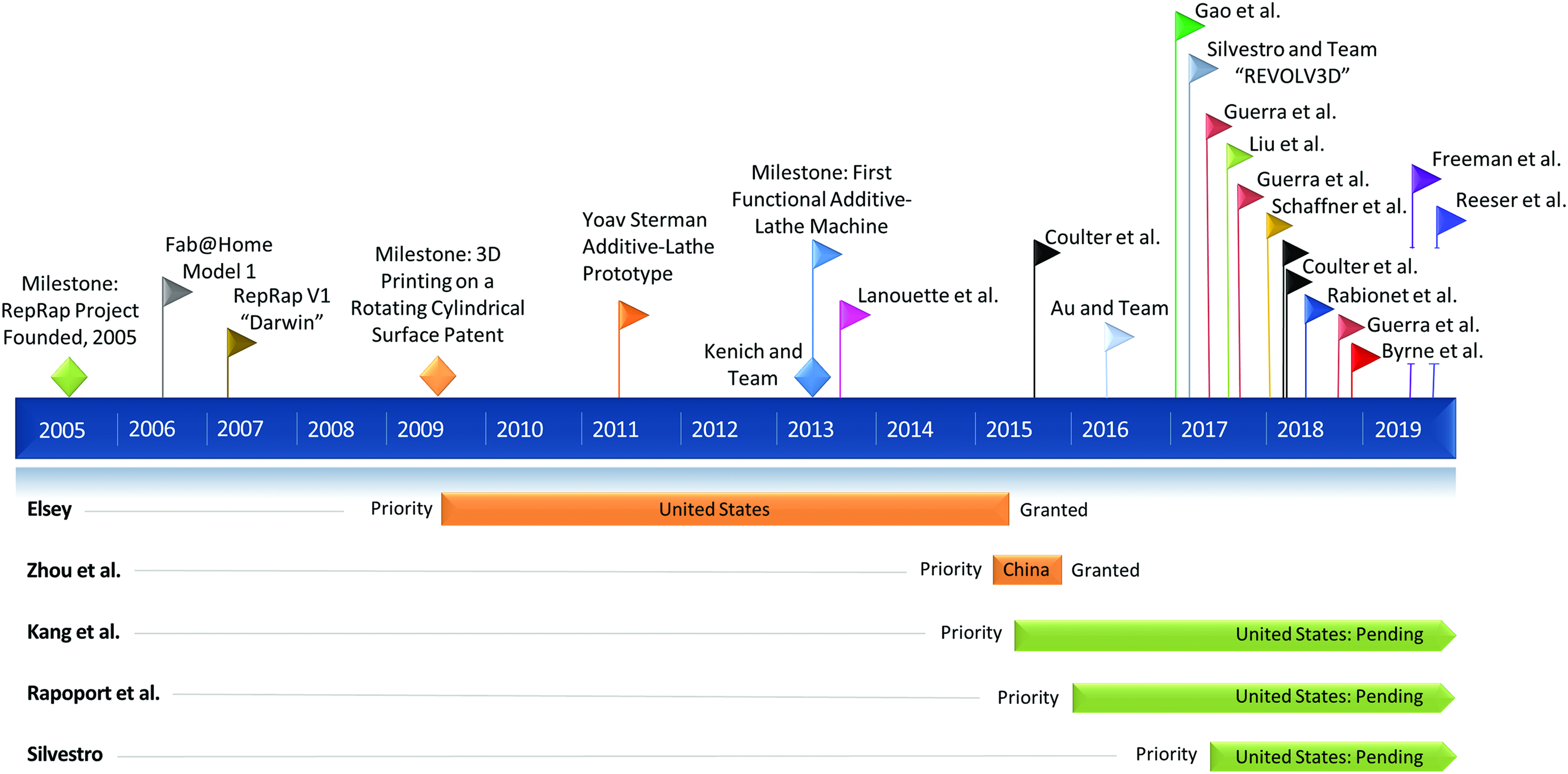
A timeline of progress to date in the history and application of additive-lathe 3D printing. Above timeline: Milestones in academic publications and additional publicly available sources. Below timeline: A selection of patents and pending patent applications. 3D, three-dimensional. Color images are available online.
Background
Standardization of terminology
Due to the relative novelty of the technology, and that the available sources are from several fields that seem not to be citing one another, many terms have been coined to describe similar features and components of this 3D printing technique. Terminology from various references is therefore summarized and standardized in this section in the hope that this nomenclature will become standard across the field.
This review describes a machine that deposits material layer by layer on a rotating cylindrical surface. Such a machine has been referred to as a: “Lathe-Type 3D Printer,” 40 “3D Tubular Printer,” 41 “‘Cylindrical’ 3D Printer,”42,43 “Rotary Printing Device,” 44 “4-axis” 3D printer,45,46 and “Additive-Lathe.”47–51 The authors choose the term “additive-lathe” for the purpose of this review as it is a unique term that accurately captures the spirit of the technology.
The rotating cylindrical surface onto which material is deposited has been variously given the name: “Mandrel,”46,52 “(Heated) Rotatory Bed,” 43 “Rod,” 35 “Starter Bar,” 49 and “Spindle.” 48 The term “mandrel” will be used for the purpose of this review.
The axis of rotational movement has been variously called the: “W-Axis,”41,43,53,54 “θ-Axis,”40,55,56 “A-Axis,” 56 and the “φ-axis.” 42 In keeping with CNC terminology, an A-axis is a rotary axis colinear with the X-axis, and the assumption of this generic hardware design as depicted in Figure 2a will be used in this review.

For clarity and brevity, any mention of a “Cartesian” 3D printer or a “traditional” 3D printer without further qualification will refer to an FDM-style 3D printer with orthogonal X, Y, and Z axes.
Additive-lathe 3D printing history
Early precedent for the principle of a layered buildup of material on a rotating cylindrical shaft is found in such varied works as those of Vaz et al., 57 who demonstrated the feasibility of a multilayered electrospinning approach for constructing blood vessel scaffolds on a rotating cylindrical mandrel in 2005. Coulter et al. developed and characterized a system for spraying even layers of rubber onto a rotatable, irregular double-curved mandrel.55,58 The mandrel was porous, allowing air to be pumped through it to inflate the rubber into a balloon postdeposition. After inflation, they developed techniques for 3D printing onto this curved surface. Adams et al. demonstrated a process for producing a 3D electrically small antenna in which the system had a priori knowledge of the hemispherical printing surface in addition to human input in the printing process, as a portion of code was repeated as the researcher rotated the surface by hand between executions. 59 These works add to the small but growing body of work in the area of surface-conformal 3D printing. Furthermore, work in curved-layer FDM has taken aim at mitigating the stairstepping and weakness in FDM parts in the Z direction, but the technique can suffer as the angle of the extruder nozzle becomes more severe relative to the printing surface.16,60–62
The concept of an additive-lathe 3D printer was proposed and discussed in the RepRap forums as early as September 2012, 63 although a United States patent for 3D printing on a rotating surface antecedes these discussions with priority dated to 2009, with the patent being granted in 2015. 64 In 2013, Kenich and team, a group of four mechanical engineering students at Imperial College London, created a functional additive-lathe printer as part of a course project. 40 Influenced by the RepRap Mendel printer, the working prototype demonstrated the importance of open-source technology in innovation surrounding 3D printing. It appears that this is the first complete and functional additive-lathe, although second in spirit to Massachusetts Institute of Technology student Yoav Sterman's project dating to 2012.47,48 Even so, the prototype demonstrates several key features of what would need to be included in a working machine.
Sichuan Revotek Co. Ltd. made headlines in 2015, and again in 2016 with the claimed successful implantation of printed vessels into rhesus monkeys, although no peer-reviewed data have been published. 65 Several additional studies utilizing this technology to create tubular vessel-like constructs using biomaterial27,44 and vascular stents of biodegradable polymers have additionally been published.43,53,54
Within the last several years, this technique began to be used in a wide variety of bio- and abiotic applications in the literature. The Senior Design project work of the “Revolv3D” team 51 appears to have generated a patent application under the name of one of the team members, 49 while Au and Team 42 demonstrate the proof-of-concept printing of alginate gelatin vessel-like structures before most other publications on the subject of additive-lathe 3D printing.
Hardware Designs and Considerations
Positioning system
In general, 3D printers all inherently perform the same function: that is, to position the deposition head at precise locations in 3D space according to a set of instructions generally delivered in the form of G-code. Some printers utilize an XY gantry system, positionable relative to a printing platform. The XY gantry may be static, while the platform is positionable along the Z-axis underneath, or the platform may be stationary, with the XY gantry positionable relative to the Z-axis. In other iterations, an XZ or YZ gantry may be positioned above a platform that moves unidirectionally in the third dimension.
Additive-lathe 3D printers substitute a cylindrical mandrel assembly for the flat printing platform of traditional Cartesian machines. This mandrel is centered on its longitudinal axis and made to rotate about that axis by a motor, and it is most useful if the exact angular position of the motor is specifiable.
Yoav Sterman's 2011 prototype “The Additive Lathe” appears to be the first physical example of a 3D printer purpose built to extrude material onto a rotating mandrel and the first introduction of that term to describe the technology.47,48 This proof-of-concept, although arguably rudimentary, highlights many of the aspects that would prove to be necessary to implement the technology in the future (Fig. 3a). A chuck mechanism was used to secure the mandrel, connected through an integrated gear and toothed belt to a stepper motor, and the extruder head was positionable along an axis colinear with the mandrel. A major functional drawback of this two-axis system was the inability to vary the distance between the mandrel and the printhead in a way that would allow for the iterative deposition of multiple layers radially outward from the mandrel.

A selection of Additive-Lathe 3D printing machines.
Kenich et al. produced the first fully functional additive-lathe printer, including z-movement capability, affording the system the functionality to print multiple layers (Fig. 3b). 40 This and other implementations41,43,51,66–68 maintain a static rotational axis positioned to rotate below an extruder, which can move along the length of the mandrel, as well as in the Z direction (Fig. 3c, d, f). Some groups chose a printer design that requires the mandrel assembly to move in the Z direction relative to the gantry system (Fig. 3e).27,42 Key considerations in this design feature are the weight and complexity of the rotating mandrel assembly.
Stepper motors commonly used in 3D printing systems offer a range of sizes and step counts to suit the needs of the system. A command for the A-axis motor to turn results in the mandrel rotating by a certain angle, and with increasing radius that angle will translate to an ever-larger arclength, traversed per step relative to the extruder. That is to say, rotation of the mandrel results in an arclength
Preparation of a traditional machine for printing includes homing of the three axes and calibration of the distance between the tip of the extruder nozzle and the print bed. An additive-lathe system introduces new homing and calibration challenges. To borrow aviation terms, the pitch and yaw of the mandrel should be aligned precisely such that the extruder nozzle maintains a set gap distance from the mandrel along the entirety of its length and that the nozzle remains normal to the mandrel. Methods of homing the mandrel axis and maintaining knowledge of its current angular position have been proposed and explored. 64
Electronics/control board
While the patent materials on the subject are broadly encompassing by nature, other references are vague about their motion control electronic components.27,43,44 Arduino is an open-source platform of hardware and software maintained and extended by contributors all over the world. 69 An Arduino shield is an electronic circuit board designed to be plugged on top of an Arduino microcontroller to expand the native capabilities of the Arduino platform. A popular choice to control 3D printing machines, the RepRap Arduino Mega Pololu Shield (RAMPS) board is a shield that was designed to load with firmware to drive a 3D printer from an Arduino Mega microcontroller. The RAMPS board has roots in the Pololu Electronics work by Adrian Bowyer, and its open-source nature combined with the low cost of components has driven the board to its current iteration. 70 The innovative designs and inexpensive cost of these control electronics drive the total cost of purpose-built and off-the-shelf 3D printers drastically down compared to the alternatives of just a few years ago. The Arduino Mega and RAMPS board combination was used by several groups in their additive-lathe printers,40,42,55,56 while another used a FabISP microcontroller board, which utilizes the Arduino integrated development environment. 47
There are quite a number of options for stepper motor control available, although two drivers are used often by the home hobbyist. Offering microstep resolution options down to 1/16-step, the Pololu A4988 stepper motor driver is a popular choice to pair with the RAMPS control board. This driver is inexpensive, providing all the control that most machines require, but tend to run hot. The DRV8825 stepper motor driver can also be used interchangeably. Its increased resolution, down to 1/32-step, and current rating come at a higher price point.
Beyond basic control of positioning system stepper motors and deposition systems, examples of sophisticated additional capabilities are offered in several cases. Rapoport et al. describe a calibration element for determining position of the extruder relative to the mandrel, 52 while Elsey suggests an encoder to track A-axis position. 64 Coulter et al. implemented a tool to map the shape of a double-curved surface before printing, consisting of a laser-based measurement device paired with an Arduino to sample the surface longitudinally and coaxially creating a digital representation of the printing surface. 56 We include the work of Coulter et al. as printing on a double-curved surface can be considered a generalization of printing on a cylindrical (single curved) mandrel, and their advancements in sampling printing surface topology and seamless circumferential printing patterns can be applied to future work in additive-lathe 3D printing.
Deposition system: extruders and mandrels
Plastic extruders, paste extruders, microvalve-based printheads, and other deposition systems used in Cartesian machines can be ported over to this new technology straightforwardly. While microvalve-based 3D bioprinting techniques could be used, low-viscosity materials commonly printed dropwise, such as collagen precursor, are highly deformable. The inversion of the mandrel during the printing process could lead to the material settling toward and collecting on the underside of the mandrel and might drip off if the weight of the material overcomes surface tension.
Coaxial nozzles have been used as a method to allow for the direct printing of perfusable channels into thick 3D printed constructs. 71 This technology has been applied to creating a perfusable system of microchannels incorporated into the wall of a larger tubular structure using an additive-lathe. 27
A unique feature of the rotational symmetry of the mandrel is the possibility of positioning the deposition tool, still normal to the mandrel, at some angle other than vertical, a suggestion put forth as a potential embodiment of an additive-lathe 3D printing system. 64 This could be possible with materials where adhesion is the primary force maintaining printed material to itself and to the mandrel. This configuration might allow material that oozes from the extruder to fall away from the system without landing on and damaging the print. The printhead might also be positioned at a non-normal angle relative to the mandrel if it suits the specific use case. 72
Published conformal printing techniques suffer from extruder not being normal to the printing surface with different curves being printed. 60 A traditional three-axis FDM machine suffices if the normal does not appreciably deviate from vertical. 16 There is precedent for a conformal printing strategy which, instead of extruding material vertically downward, utilizes a deposition needle physically bent at an angle to better approximate printing normal to a curved surface. The angle of the bend was fixed, which may come closer to normal to steeper curves, but still suffers from a similar issue of a fixed angle. 59 A five-axis machine would be ideal such that an extruder might always be normal to a surface at the point of deposition.
Nebulization of chemicals over 3D printed biomaterial for the purpose of crosslinking has been explored in the bioprinting literature.8,9,20,21,73 Aerosol deposition of silicone by Coulter et al.55,58 and the understanding of how deposition speed, time, and amount affect that result could be applied to the aerosol deposition of liquid components in additive-lathe printing and postprocessing. In their patent applications, Kang and Zhou suggest that spray nutrition could be deposited onto the surface of the print, while a nutrition delivery system built into the mandrel would allow for nutrition supply and biostimulation from the luminal surface. 74 Such a porous mandrel design allows for the potential of not only supplying liquid nutrition or crosslinking agent to the inner surface of a bioprinted construct but also the supply of humidified air containing CO2. For this use case, a 3D printed mandrel may well be utilitous. 75
In plastic deposition FDM, it is often necessary to insert a thin tool between the completed part and the build plate to separate the part from the platform. This could cause an issue in circumferentially-closed parts printed on the additive-lathe, in that there is no room to insert a tool between a print and the mandrel and cannot be pried away in the same manner. Plastics commonly used for 3D printing have also been shown to shrink slightly upon cooling, 76 exacerbating this potential issue. The idea of using a sheath of sleeve over the mandrel had been put forth for both biological and nonbiological applications as a way to ensure adhesion of a select material, as well as to facilitate the removal of the printed structure at the opportune time.49,52
Other mid-print or postprocessing modules have been suggested. For postprint surface quality, a sharp-edged “shaper” may be used on a layer-by-layer basis to smooth any imperfect features caused by overextrusion. 64 A heating unit could be used at the end of a print, with the mandrel rotating, to maintain the surface of the print at the glass transition temperature long enough for surface imperfections to melt and merge. 49 A chemical vapor bath might be used as well, which could too benefit from the aerosol deposition work mentioned previously. This concept could be broadened into UV curing, nebulization, or cross-linking baths for the purpose of 3D bioprinting. The ability to access a printed part from all directions gives the technology great range in incorporating different mid-print and postprint modular accessories.
A heated mandrel would allow for additional materials to be printed, such as ABS. External means of heating the mandrel could be implemented, as well as including a resistive heating element interior to the mandrel or sleeve, connected to the control electronics using a brush and commutator connection.
Software and Control
Three-dimensional printing on a rotating mandrel poses a series of novel challenges to accompany the opportunities the technology affords. While Elsey includes in his U.S. patent a section on certain theoretical aspects of developing a slicer that intersects a model with imaginary cylinders instead of slicing planes, 64 no current commercial or open-source software exists specifically for slicing a CAD model for printing with an additive-lathe 3D printer.
Recently, in conjunction with a collaborator, we detailed the first full implementation of slicing and closed-contour construction for 3D printing nontrivial geometry on the surface of a cylindrical mandrel based on reimagining traditional slicing theory. 77 In brief, the slicing planes of traditional slicers were replaced with slicing cylinders or slicyls (Fig. 2b–e). A series of concentric slicyls are intersected with an STL model, and intersection points are stitched together into their respective closed contours. Several edge cases were identified and addressed. Robust methodologies for generating infill patterns, support structures, and other considerations for toolpath construction are required before full implementation of a machine capable of printing complex geometry from a digital model onto a rotating cylindrical surface.
Consider the simple case of printing an open cylindrical tube of constant wall thickness. A cylinder printed vertically using a traditional 3D printer would generally consist of a stacked series of printed rings. The G-code to print each ring would remain the same, with a printer command to adjust the location in the Z-axis with each layer. It is readily apparent that if a cylinder were to be printed on an additive-lathe and that cylinder were to consist of several layers adding to the thickness of the cylinder wall, then each layer applied to the mandrel would increase the effective size of the surface onto which the subsequent layer will be applied. The code for each layer will need to be modified according to diameter and the type of layer applied.
While in traditional 3D printing, each layer is added within certain boundaries in the same predefined space, the coordinate surface onto which cylindrical layers are added grows with increasing radius. That is, the diameter of the coordinate surface increases by two times the layer height with each added layer. Less obvious is that with increasing radius, and therefore decreasing curvature of the coordinate surface, the cross section of a 3D printed trace will change, in addition to the change in cross section with geodesic angle. For complex models, software generating geodesic tool paths must account for this change in cross section, which does not occur in traditional 3D printing.
Slic3r, an open-source platform for slicing and generating G-code for traditional printers, has been used in a clever manner to generate toolpaths for the additive-lathe. 40 Parts were modeled and sliced as if they were flat. Modeled parts did not resemble the desired final part at all, which limited complexity to those that could be visualized as flat. The team also employed a second method using a custom MATLAB code for producing printed cylinders, which allowed for updating angular velocity with radius and also for producing code for layers that changed printing direction, instead of relying on what the Slic3r toolpath generator decides.
Coulter et al. appear to use the most sophisticated software implemented to date, in which auxetic structural designs are printed on irregular double-curved surfaces up to six layers thick. 56 They used the parametric modeling plug-in Grasshopper3D for the 3D modeling software Rhino to create reconstructions of the laser-scanned double-curved surfaces, calculate toolpaths along those curved surfaces, and finally to generate G-code to implement those toolpaths. Their methodology for generating these specific patterns is a generalization to the less-complex, single-curved cylindrical printing surface. Their solutions could be implemented in additive-lathe printing, for example, in the area of 3D printed auxetic stents.
In traditional 3D printing, a component in a layer is generally constructed by first printing a polygonal boundary, which is the output product of a slicer, and filling that boundary in by some percentage with an infill pattern. Some of the more simplistic applications of the additive-lathe demonstrated thus far have in some ways blurred the lines between boundaries and infill with the proposition and utilization of types of layers for constructing solid models. Spiraling layers27,42,44 and axially-oriented layers 50 have been utilized, and other types of layers have been proposed.49,78,79
Bioprinting, with its soft material, large trace size, and crosslinking time, would seem to be more forgiving in terms of toolpath calculation, especially for the simple case of tubular vessel printing. The printing schemas in the area thus far have primarily utilized a spiraling toolpath for printing these unbroken tubular structures, with one publication detailing how to synchronize the movement of the various axes to prevent over- or under-extrusion, while allowing the adjacent traces to merge together. 44
Suggestions made for such a toolpath generation software solution include: treating intersection points in a reduced cylindrical coordinate system, exporting into a bitmap file for further processing, and designing toolpaths to limit frequent changes in direction, especially of the rotating mandrel. 64
Some examples imply the use of cylindrical coordinates and the development of slicers that output toolpaths in cylindrical coordinates, yet the authors do not clarify exactly how this is achieved.49,50 For others, a hand-coded set of toolpaths has ostensibly been created for the specific application.
Open-source 3D printer microcontroller firmware such as Marlin does not natively support a rotating axis as is necessary for additive-lathe 3D printing. 80 The firmware expects the rotation of a stepper motor to be converted to linear movement through lead screws or belt-drive systems. With this in mind, Coulter et al. performed a “hack” allowing for a setting of rotations per millimeter and then ostensibly provided G-code to the microcontroller in the form that a traditional 3D print would expect. 56 It is important to note, however, that a setting of rotations per millimeter would be intimately tied to diameter, and the increased surface velocity and arc length over which to print per unit angle would need to be tied to the extrusion command to maintain consistent trace cross section with diameter. A hack of steps per angle while feeding the microcontroller a G-code in cylindrical coordinates may be a solution with wider applicability. The E command would need to be tied to actual arc length traveled, accounting for surface velocity relative to printing head and mandrel printing surface dimension. For Coulter et al., maintaining a consistent trace size required a constant linear velocity approach to printing, necessary to limit the off time of their pneumatic extruder system. Unlike the stepper-motor driven extruders of traditional desktop 3D printers that offer easily-variable flow rate and filament retraction, careful correlation of extruder and printing surface movements is essential for multilayered printing on a curved surface.
Yoav Sterman ostensibly developed a program in Processing to create commands to interface with his FabISP board to dictate height, pitch, and direction of printed springs. 47 The authors could find no publicly available images of the printed springs generated from the project; however, this work is functionally similar to the conformal printing on a rotating mandrel study of Lanouette et al.81,82
It should be noted that additive-lathe 3D printing would still require support structures for certain geometries incorporating overhanging features and that no references have demonstrated use thereof as of the time of writing.
Applications
Table 1 details the materials and cell types (if applicable) used in the various nonbiological, biological, and interdisciplinary applications of additive-lathe 3D printing technology to date. In their proof-of-concept work, Kenich et al. describe the potential mitigation of anisotropy in 3D printed cylinders by opposing the direction of printed PLA with each layer added, compared to a traditionally-printed cylinder consisting of a stacked series of disks (Fig. 4a, b). 40
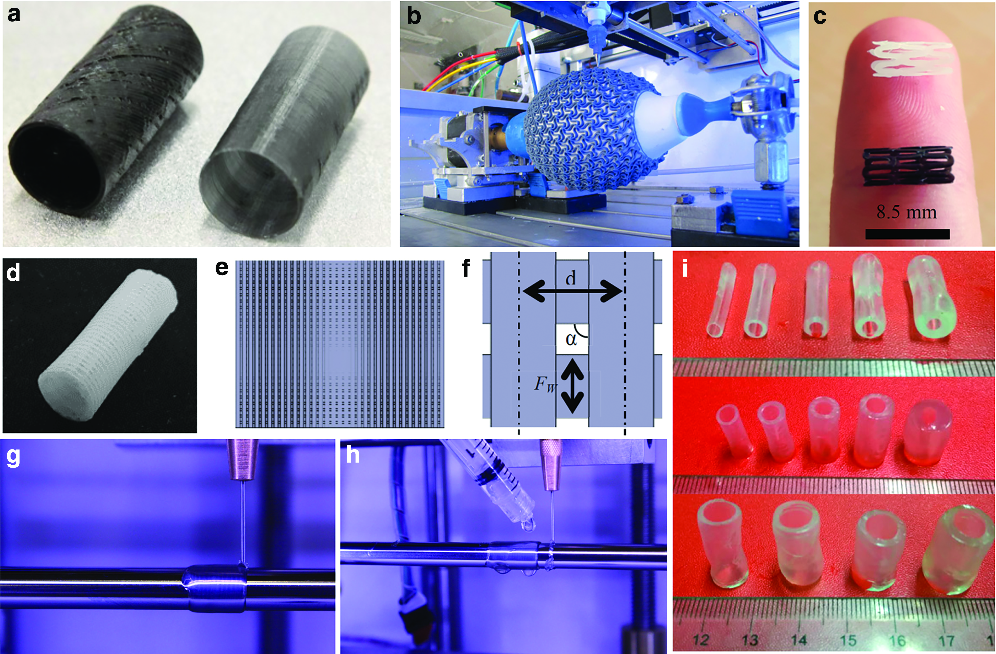
A selection of constructs created by additive-lathe 3D printing.
Printed Examples of Additive-Lathe 3D Printing Applications
Thixotropic mixture of Thomtastic 73 (silicone), hardener, and kaolin powder.
Proprietary bioink formulation by Sichuan Revotek Co. Ltd.
Unknown type or origin.
PCL, polycaprolactone; PLA, poly(lactic acid).
In late 2016, Sichuan Revotek Co. Ltd. claimed the successful implantation of 3D bioprinted blood vessels into 30 rhesus monkeys, constructed with Revotek's T-Series™ 3D Bio Printer, although the work has not been published in a peer-reviewed journal.65,66 A 2 cm section of the abdominal aorta was claimed to be replaced with the bioprinted vessel, having found to merge completely with the native tissue 1 month postsurgery. This achievement demonstrates the power of even the most basic application of additive-lathe technology for tissue engineering.
In their patent applications, Rapoport et al. described a comprehensive list of materials and cell types used with their additive-lathe, establishing precedent for printing of such tubular biological structures as: blood vessel-like constructs, intestine-like constructs, and tissue of the respiratory system. 52 The concept of 4D printing is explored, with indefinite delay time between printed layers proposed, if necessary. Relatedly, transglutaminase in bioink has been shown to aid in adhesion between layers in 3D printing applications, which could be used to ensure successful time-delayed addition of layers with the additive-lathe.22,23 Suture pullout experiments demonstrate that additive-lathe 3D printing is a viable option for the future of vessel replacement surgery. 52 This work, in combination with the other work in 3D printing artificial vessels, fluidic channels, and tubular scaffolds, represents an area of great utility in the discipline.
In a series of studies, Guerra et al. demonstrated the utility of their additive-lathe in the manufacture of 3D printed bioresorbable stents. 43 In one study, single-layer polycaprolactone (PCL, Capa 6500®; Perstorp) stents with a diamond cell structure were printed while varied temperature, printing speed, and material flow rates were examined for their effect on the final printed product. Both printing temperature and PCL flow rate were found to have a strong influence over stent strut width. While printing speed alone did not have a clear effect on strut width, the combinations of speed flow and speed temperature may influence the physical properties of the resultant stent.
In a follow-up study, the effect of the previously-tested printer settings (with the addition of printer trajectory) on various stent model features, along with a series of radial expansion and recoil tests, was performed. 53 PCL viscosity is inversely proportional to temperature, affecting the spread and cooling time of the printed strut; temperature along with flow rate was again confirmed to be dominant parameters in the dimensional precision of the final product. Printed on a mandrel of diameter 5 mm, resulting in a stent of commensurate inner diameter, 3D printed stents showed an average maximum uniform radial expansion of 320% and an average recoil of 22.78%. Guerra et al. state that their work demonstrates the utility of this one-step stent manufacture process on reducing the time and cost of producing patient-specific micro medical devices.
Expanding on their previous studies, Guerra et al. used additive-lathe 3D printing to produce multilayer composite stents with PCL and PLA with designs incorporating several unit cell geometries (Fig. 4c). 54 The composite stents balanced out the negative physical properties of the base materials with improved radial expansion and recoil properties, along with a middle ground dynamic storage modulus, when comparing those properties to their single-material printed counterparts. Murine 3T3 fibroblast cells seeded onto individual PCL and PLA scaffolds showed a 33.5% greater cell proliferation on PCL compared to PLA after 3 days of static culture. These initial cell proliferation studies demonstrate potential for using composite stents to encourage reendothelialization while mitigating potential restenosis, but will require additional future studies, including incorporation of human endothelial cells cultured under dynamic conditions.
In the field of soft robotics, Schaffner et al. and Byrne et al. created pneumatic soft actuators composed of a stiff thermoplastic elastomer (TPE) reinforcement layer of varying design sandwiched between two layers of silicone.45,46 Elongation, contraction, and twisting motions were achieved when these bioinspired actuators were inflated with air, depending on the design of the TPE layer.
Rabionet et al. have investigated the use of additive-lathe 3D printing to manufacture small diameter tubular scaffolds for tissue engineering. 41 The PCL (Capa 6500; Perstorp) scaffolds featured a four-layer design, with a liquid-impermeable inner layer and three subsequent layers forming a network of pores by spacing adjacent printed traces by 0.5 mm and printing traces orthogonal to the previous layer (Fig. 4d–f). Murine NIH/3T3 fibroblasts were seeded onto sterilized scaffolds printed with varying fabrication parameters to investigate which affected fibroblast growth on the 3D scaffold. A cytotoxicity assay revealed an inverse relationship between all three parameters (printing temperature, printing speed, and material flow rate) and cell proliferation after 6 days of culture. The tested parameters have been previously shown to affect material trace thickness.43,53 Parameters increasing trace thickness result in a decrease in printed pore size, which the authors believe may have hindered nutrient exchange within the scaffold. Rabionet et al. state that this study demonstrates the importance of proper selection of application-specific printing process parameters for successful use of this technology in tissue engineering applications. These novel scaffold printing and seeding procedures could be applied to myriad applications beyond vascular tissue engineering (bone, trachea, etc.) with the substitution of application-specific cell types.
In perhaps the first physical demonstration of additive-lathe 3D bioprinting, Au et al. establish the basic utility of the additive-lathe to produce vessel-like tubes with an alginate-gelatin bioink crosslinked with calcium chloride (Fig. 4g, h). 42 Liu et al. utilize an alginate-gelatin bioink to explore the effect varying parameters have on the size and shape of printed vessel-like tubes (Fig. 4i). 44 Freeman et al. studied the effects of the heat treatment and concentration of gelatin on the printability of a gelatin-fibrinogen blended bioink in the creation of tissue-engineered vascular grafts using additive-lathe technology. 83 Using a deposition nozzle system detailed in a previous study, 71 Gao et al. produced alginate vessel-like structures featuring multilevel fluidic channels through which embedded cells could receive nutrients using perfused cell culture media. 27 Figure 5a depicts a vertically-printed vessel deformed under its own weight, an issue mitigated by utilizing additive-lathe 3D printing (Fig. 5b). Varying vessel sizes and topologies are additionally shown in Figure 5c–f. Potential further applications of the work of Gao et al. are depicted in Figure 6.
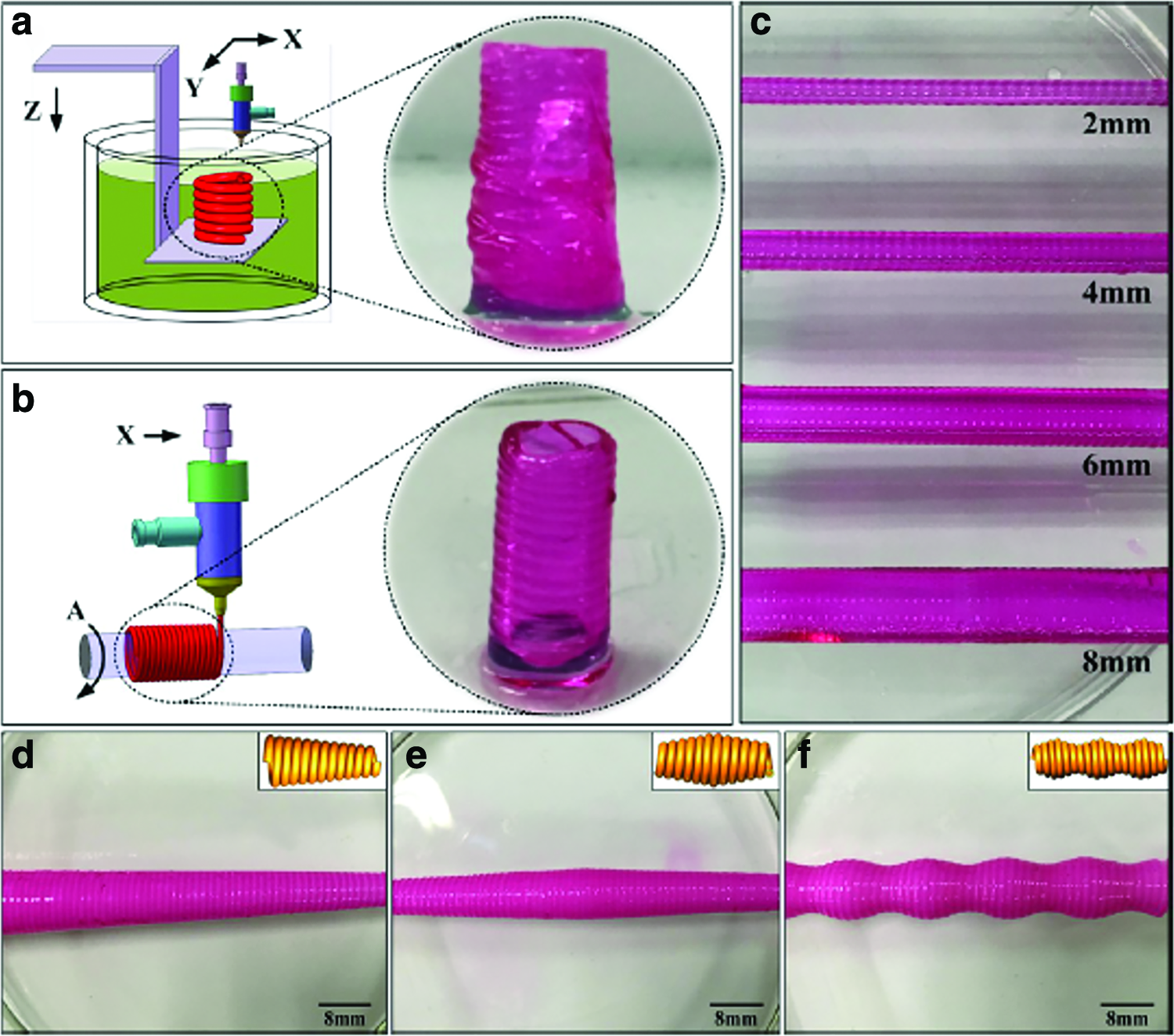
Characterization of the fabrication method.
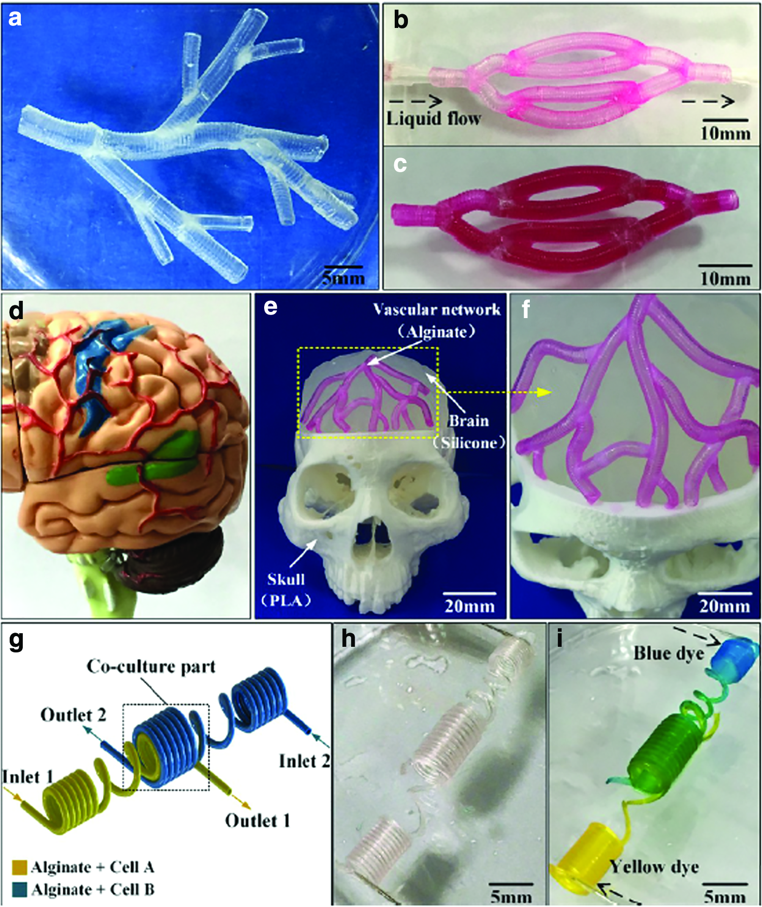
Potential tissue engineering applications of the vessel-like structures.
Discussion
As with all additive manufacturing modalities, additive-lathe-type 3D printing has several shortcomings to be considered before its employment. As it remains an FDM technique, in practice constructs with complex curved topology will suffer from stairstepping in the radial direction. Prints may additionally require support structures and sacrificial material. As the additive-lathe is intended to supplement the abilities of traditional 3D printing and not replace it, the user will determine applicability and best practices on a case-by-case basis.
Current examples of additive-lathe technology create structures of predetermined inner-diameter utilizing mandrel sizes purposely selected for a specific print, similar to how commercially available electrospinning machines utilize mandrel collectors of various predetermined diameters. 84 This is a functional deficiency in comparison to the blank slate of a traditional build platform. Thus, there is room for innovation in dynamically adjusting the initial diameter of the mandrel. A bio-inert silicone or polydimethylsiloxane (PDMS) could be aerosolized and applied to a mandrel to bridge the gap between initial mandrel size and the diameter needed for a specific print, incorporating methods laid out by Coulter et al.55,58 Alternatively, or in addition, a sacrificial material could be printed before application of any part of construct material. Utilizing base-layer support material will open the technology up from basic constructs with cylindrical bore holes to providing for printed internal topology. Thus, the ribbed inner topology of the trachea could be reproduced, instead of a ribbed outer topology with smooth inner topology. Finally, precedent has already been set for this technology to utilize noncylindrical mandrels for establishing predetermined inner geometry, such as in the creation of heart valve prosthesis. 85
There does not currently exist off-the-shelf or open-source toolpath generation software for additive-lathe 3D printing machines nor is there a complete theoretical framework in the literature to create one. Although several groups reviewed herein have produced additive-lathe hardware, this lack of general, purpose-built software restricts the utility of these machines to basic hand-coded toolpaths or application-specific work-arounds. Building off of the efforts of our recent work, 77 additional work needs to be done before a complete toolpath generation software for additive-lathe 3D printing is realized. Novel, seamless infill patterns may need to be developed that are able to change with changing print radius.
Utilization of a traditional 3D printer to create various tubular biostructures and other objects with trans-axial bore holes is an attempt to make the best of a technique not well suited to the task. Using additive-lathe technology could provide a better method for these certain applications. Similar to the early days of additive manufacturing, existing and future additive-lathe patents may limit the commercial availability of additive-lathe 3D printing systems to the general population and stymie the advancement of hardware and software advancements to this modality. In fact, offered in conjunction with their Modular Rollovesselar™ platforms, Sichuan Revotek's T-Series 3D Bio Printer is the only commercially available additive lathe-type 3D printer at the time of writing. 66
Progress from the first stereolithography additive manufacturing concepts in the early 1980s, with the first patent granted in 1986 86 and patent for FDM apparatus in 1989, 87 was only accelerated to the average user 20 years later with the launch of the RepRap and Fab@Home projects. The power of open-source technology is readily apparent; this collaboration prevents reinventing the wheel. Even now, one of the biggest brands of 3D printer, Ultimaker, open sources both their hardware designs and their software platform Cura, an apparent homage to their open-source roots. 88
Malone and Lipson note the escape from the “chicken-and-egg” paradox of early computing while addressing their aspirations for the Fab@Home project. 2 With great similarity to the home computing revolution, 89 by making an affordable 3D printer design, they believed that researchers and home hobbyists would have the opportunity to advance the technology, making it more attractive to others, sparking a similar cycle of technological advancement. When Adrian Bowyer founded the RepRap project in 2005, his vision was to apply the principles of genetic evolution to 3D printing. 1 He succeeded in demonstrating this objective, with dozens of RepRap designs in existence today, all traceable to those earliest self-replicating prototypes. A large number of users taking an interdisciplinary approach to expanding the utility of additive-lathe 3D printing would be required to see the type of exponential improvement which was seen in Cartesian 3D printing. Nevertheless, the examples in this review serve to show that the proof-of-concept groundwork for adoption of additive-lathe 3D printing in multiple fields has been laid.
The authors consistently found little acknowledgment of the additive-lathe 3D printing work of others in the subject literature, often citing their printers as novel technological advancements. This review serving as a technological nexus, future users and innovators of the technique must do better to cross-reference learning from and acknowledging the work of interdisciplinary peers, lest emerging technologies become so sequestered that their potential is squandered.
Conclusion
The authors intended for this review to serve as an encompassing view of the history and current state of additive-lathe 3D printing, drawing from the collective knowledge of the literature and the prior art in publicly-accessible patents and patent applications. Additive-lathe 3D printing technology offers significant advantages over traditional FDM for certain geometries in bioprinting and desktop rapid prototyping. Additive-lathe 3D printing has proven utilitous in several disparate fields, and future adopters of the technology should be able to build from the foundation herein explicated and focus on applications of greater complexity and utility.
Search Strategy
The authors used a wide search to identify the lineage of additive-lathe 3D printing technology, which included Google and YouTube searches for “3D printing,” modified with the terms: “Additive-Lathe,” “Rotational,” “Cylindrical,” “Rotary,” “Mandrel,” “Rotating,” “4-axis,” “Shaft,” and “Curved Surface.” The same terms were used to search the art in Google Patents and the literature in Google Scholar, PubMed, and Science Direct. We have to the best of our knowledge identified the groups and fields involved in the inception of additive-lathe 3D printing, along with those currently utilizing and expanding this new technology either peripherally or directly.
Footnotes
Author Disclosure Statement
No competing financial interests exist.
Funding Information
No funding was received for this article.