
Abstract
Curved-layered fused deposition modeling demands a curved mandrel for each of the designs to fabricate. This results in more fabrication time and material used. To overcome this, an adaptable pin-base mandrel is presented. The fabrication of curved structures with such mandrel uses the extruder as a pushing tool, pushing each of the pins to the depths required for each surface. After the base surface is formed, the conventional process of curved fused deposition modeling (FDM) is used. Several lattice shell structures composed of nonplanar layers were fabricated on FDM mandrels and the adaptable pin-bed proposed here. The comparison of the manufacturing results showed that the adaptable base allows the successful fabrication of the samples. The solution exposed here represents a proof of concept to validate the idea. The adaptable base presented in this study is unique and it brings advantages to the fabrication of curved-layered structures.
Introduction
Parts fabricated with fused deposition modeling (FDM) result with the so-called stair-case effect, 1 which compromises surface quality and structural performance. 2 To overcome this, the concept of curved-layered fused deposition modeling (CLFDM) has been explored, where parts are manufactured by stacking nonplanar layers. These curved parts have continuous extruded filaments (rasters) along the curved form resulting in better structural properties. 3 Significant effort has been made on the fabrication of parts with CLFDM covering from upgrading the mobility of the FDM machines4,5 to path planning of the extruder.6–9
CLFDM requires a base on which the material is deposited (referred here as mandrel). This is three-dimensional (3D) printed 10 and is used several times provided that the geometry is not modified. Changes in the intended geometry demand a new 3D printed mandrel, hence, more material used. In response, this study presents a base that can adapt to different geometries evading the use of the printing material. The approach presented is a proof of concept, final materials and add-ins to be used are still under study.
Materials and Methods
Adaptable bed setup
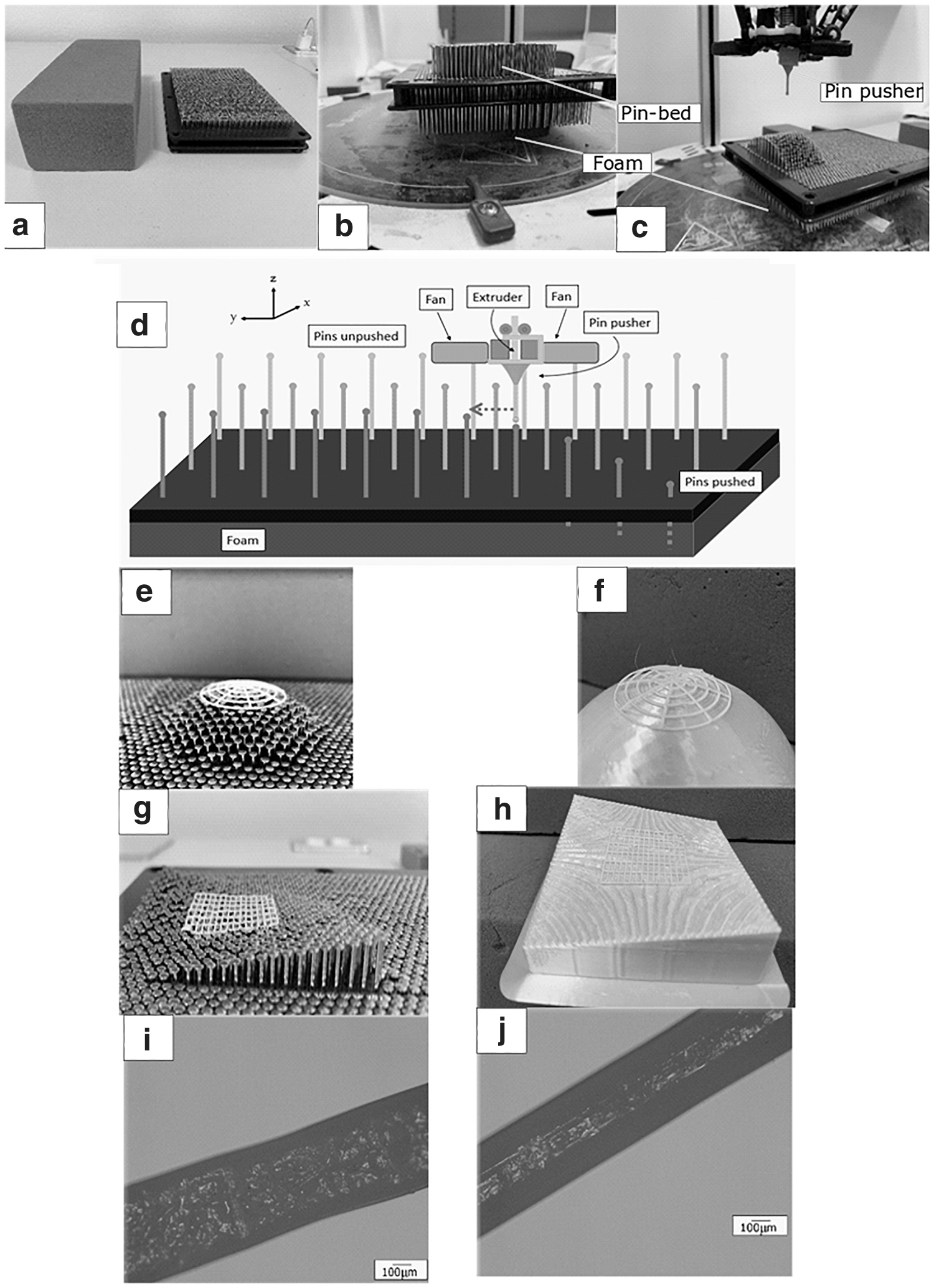
The adaptable bed uses two elements: a pin-bed (PEICEES® 6″8″) and a foam (OSASIS® fine-celled thermoset phenolic plastic foam; Fig. 1a). The printer used for this study is Rostock V3.2 Max 3D. The working principle consists of all the pins starting at their maximum height (distance from the top of the pins and the top section of the foam), then they are pushed (nailed) downward, while the foam keeps them at the height required to form the mandrel. The pin-bed is placed on top of the foam (Fig. 1b). The pins have an initial height of 18 mm and a diameter of 1 mm. To keep the pins at the right depth, the foam was selected neither too soft to avoid looseness nor too stiff to require high magnitudes of force to push the pins.
Fabrication setup,
A tool to push the pins was designed with a spherical tip (Fig. 1c). This tool fits on the extruder and increases the allowance angle to conform surfaces with sharp changes on slopes, while pushing one pin at a time, avoiding the collision between the fans and the pins. Considering the distance from the center of the tool to the contact point with nearby pins as ρ, a reduction on the slopes achievable results whenever ρ is greater than the diameter of the tool tip. The complete setup is shown in Figure 1c, where a section of a cylinder is presented as an example of a mandrel.
Forming mandrel on the pinned-base: G-code generation
The extruder trajectories to form the mandrels on the pin-bed were generated through MATLAB® scripts where the intended form was parametrized and discretized in segments of 2.5 mm (pin head diameter). The trajectory of the pin pusher involves moving in the z- direction, nailing one pin at the time into the foam. Then the extruder moves in z+ direction, next in the xy-plane to the following location (Fig. 1d). The process is repeated until all the pins are nailed at the right depth required to conform the shape needed. The fineness of the mandrel depends on the dimensions and location in xy-plane of the pins. The Rostock machine has a x–y and z resolution of 100 and 12.5 μ, respectively. This positional accuracy keeps each pin at the correct height to attain the predefined shape on the pin-base.
The concept presented in this study was tested with two different mandrels: a fraction of a sphere with radius of 50 mm and a surface formed by
G-code generation for nonplanar lattices
Another script was developed to generate the trajectories to print the nonplanar lattice samples. The semispherical lattice had a radius 50 mm with five circular rasters and meridians rasters separated at 45°. The complex surface lattices consisted of rasters in the yz-plane and xz-plane separated by 2 and 5 mm, respectively.
The samples were fabricated with white polylactic acid (PLA). Nozzle trajectories were discretized in linear segments of 1 mm length. The spherical lattice was parametrized using polar coordinates, discretized by 1°, which was roughly 0.87 mm. These lattice structures were printed on both the adaptable bed and FDM mandrels. Tape was added to enhance adhesion while facilitating the removal of the sample. FDM mandrels were modeled in SolidWorks® and manufactured with green PLA, 10% infill, and layer thickness of 0.2 mm.
Results and Discussions
Mandrels formed on the pin-bed
The two mandrels formed in the pin-bed are presented in Figure 1e and g. If a geometrical change is demanded and a new mandrel must be formed, the foam is removed manually from the bottom of the pin-bed. Then, placing the foam block again pushes all pins back to the original height. The geometric accuracy was quantitatively validated by pushing only one pin to a total distance of 10 mm. Taking the total height of the pin to be 18 mm (prior pushing), the resulting height was measured using a digital T&O® Vernier. The average of 11 heights measured was 8.08 ± 0.36 mm when compared with the expected height, results an error of ∼1%.
3D printed mandrel versus pin-bed mandrel
Considering the pushing tool traverse speeds, 1500 mm/min upward and 1000 mm/min downward, the total setup times to form the pin-bed mandrels and the amount of printing material demanded to produce one sample are presented in Table 1. For both FDM-printed and pin-bed mandrels the material used for the samples was obtained by weighing them in an Analytical Balance ME54E by Mettler Toledo®. Weights showed a significant saving in material employed. Fabricating the samples on an FDM mandrel demands >1000% of material. The pin-bed setup requires additional components, that is, the foam, the pin-bed; however, the amount of saving in materials justifies this. The pin-bed costs 20 USD and one piece of foam costs 0.4 USD (split into eight sections in this study); contrarily, every printed mandrel costs ∼1 USD.
Comparison of Manufacturing Times Printed Mandrel Versus Pin-Bed
The nonplanar lattices fabricated on the FDM mandrel were placed on the pin-bed and vice versa (Fig. 1e–h). Results were compared with an inverted optical microscope with a magnification 50 × by ZeissV® (Fig. 1i–j). Regardless of the mandrel used, similar results were observed: (1) a rough bottom surface due to the tape and (2) defects on the top layers attributed to imperfections of the nozzle. From these, rasters diameters from both mandrels were measured. A minimal difference of ∼30 μm measured can be attributed to the pins being at lower heights than the intended ones.
The approach presented worked properly for lattice samples. Several opportunities were identified for improvements. Important reduction in formation time of the mandrel on the pin-bed can be obtained by automating the pins displacement, however, including linear actuators for such a number of pins could result in an expensive setup. Increasing the number of pins with smaller diameters will allow a finer discretization of the surface to be formed benefiting the fabrication of quasi-solid structures. When printing structures where the rasters are placed next to each other, a poor number of pins could lead to defects on the surface finish.
The proposal presented could be used in setups where the platform has mobility if the pin-bed is properly mounted on the platform. Once the pins are nailed, the foam could keep them in position regardless of the movement of the platform.
Conclusions
A proof of concept of adaptable mandrel for CLFDM was presented. Different curved structures fabricated with conventional FDM mandrels and pin-beds were compared to expose the advantages of the proposed solution. The use of a pin-bed resulted in saving of printing materials, as the only material used was the one needed for the part to be fabricated. When considering a new geometry, the saving in material is highly more significant, as no need for a new printing for the mandrel is required. The pin-bed presented is adequate for the fabrication of lattice-type samples. Future study points toward a finer distribution of pins for quasi-solid samples.
Footnotes
Acknowledgments
We acknowledge the support of the School of Engineering Sciences at Tecnológico de Monterrey in Querétaro, and also the aid of Miss Dakini Montañez in the generation of the figures of this article.
Author Disclosure Statement
No competing financial interests exist.
Funding Information
No funding was received for this article.
References
Supplementary Material
Please find the following supplemental material available below.
For Open Access articles published under a Creative Commons License, all supplemental material carries the same license as the article it is associated with.
For non-Open Access articles published, all supplemental material carries a non-exclusive license, and permission requests for re-use of supplemental material or any part of supplemental material shall be sent directly to the copyright owner as specified in the copyright notice associated with the article.