
Abstract
Elastomer composites have proven to be promising functional materials for soft actuators. Direct manufacturing of these materials is a practical prerequisite for Soft Robotics applications, where form and function are intricately entangled. In this article we show a multimaterial printer and associated processes for in situ fabrication of silicones and silicone-based elastomer composites for soft actuators. We discuss the fabrication process for both the silicone/ethanol composite material and encapsulating silicone skin using an inline passive mixing system, followed by characterization of the rheological and mechanical properties of the printed materials for various print modalities. Rheological study revealed the conditions, allowing continuous 3D printing of both small and big items out of silicone rubber and silicone/ethanol composite. Anisotropic mechanical properties allow for the design of functional characteristics of soft actuators by choosing print design modalities. We demonstrate a single-print-job additive manufacturing of functional multimaterial systems for soft actuation, and suggest that the developed processes will allow us to design soft robots with a broad range of actuation characteristics.

Introduction
Bioinspired engineering aims to mimic natural design and functionality to create advanced solutions in a broad variety of fields. Using soft matter allows researchers to replicate biological systems and even create interaction with biological tissues. Silicone rubber has been one of the most important soft materials for various domains, from biology and medicine to robotics. In the prosthetics field, silicone has been used through molding since the second half of the 20th century.1–3 In Soft Robotics, which focuses on development of nature-like maneuverability and dexterity by exploring compliant materials,4,5 polymers, and mainly silicone elastomers, have become the dominant materials in the past decade. Particularly, they have been widely used for soft actuation due to their compliance. 6 Mostly, soft robotic bodies and soft actuators have been fabricated using soft lithography7–9 or other types of casting,10–12 including casting of elastomer into 3D-printed molds.
Precise and rapid direct fabrication of silicone rubber with minimal geometrical shape constraints has become of great importance for all its application fields. 3D printing may make it possible to unleash the full potential of silicone and silicone composites in intricate design and fabrication of soft actuators with multiple degrees of freedom. Various techniques have been employed to 3D-print different types of soft matter for soft actuation.13,14
Direct 3D printing of silicones has been a challenge, and several concept proofing attempts have been made at both industrial and academic levels. 15 In 2015, the Wacker Chemie AG Company announced its commercial silicone 3D printer. This machine has used UV curing of silicone drops extracted from the specially designed nozzle to create 3D structures. 16 Tian et al. reported the use of a process of a silicone foam formation by extruding liquid silicone from a specific height to form coiled structures. 17 Wu et al. 3D-printed a polydimethylsiloxane (PDMS) matrix with gas-filled microspheres, and obtained recoverable (shape memory) mechanical response of the printed structures upon heating the material above the microspheres' glass transition temperature. 18 Ozbolat et al. have shown superior mechanical and cell adhesion properties for 3D-printed heat-cured silicone for medical and biological applications as an alternative for soft lithography and casting. 19
Multimaterial 3D printing was used for design and fabrication of silicone/carbonyl iron magnetorheological hybrid elastomer with controlled structures. 20 Huang et al. showed successful 3D printing of conductive silicone/carbon-fiber composites and their implementation as strain sensors. 21 Liravi et al. have developed a hybrid 3D printing setup for medical applications. Their 3D printing concept has included three types of print heads in a single machine: piezo-pneumatic jetting, and solenoid-based and pneumatic extrusion. Printing of non-Newtonian silicone has been demonstrated at improved rates. 15 Yirmibesoglu et al. developed a 3D printer and an extrusion process for direct 3D printing of commercially available silicone for soft robots. The authors compared the fabricated parts with cast counterparts and found the performance to be equal or superior. 22 Abdollahi et al. developed an expert-guided optimization strategy syringe-extrusion 3D printing of PDMS with various process and design parameters. 23 Coulter and Yanakiev have developed a system for 4D-printing silicone rubber for soft actuation. 24
Wallin et al. has discussed various materials and techniques for 3D printing of soft robots, including silicones and other polymeric materials, such as hydrogels and polyurethanes. 25 Khondoker et al. developed a method for extruding two immiscible thermoplastic materials through a static intermixer and applied it for 3D printing of tendon-driven robotic fingers with soft and rigid components. 26
Material-based approaches have been implemented to develop a reliable silicone 3D-printing process. Walker et al. attempted to control the silicone rubber curing and the related viscosity for 3D printing passive silicone structures. 27 Jindal et al. have endeavored to develop a biocompatible silicone rubber, which could be directly 3D-printed to form facial and body prostheses. PDMS chain length and cross-linker concentration have been altered to find the optimal formulation for 3D printing of maxillofacial prostheses, for which a combination of high tensile and tear strength, elongation, and appropriate hardness should be achieved. The study recommends using two-component room temperature vulcanized (RTV) silicone with 5 wt.% of cross-linker, RTV catalyst, and moderator or thixotropic agent. 28 The effect of the last two additives has been tested in the later study by Jindal et al. The authors have reported one of the tested compositions as optimal for 3D printing of prostheses. 29
Alternatively, Roh et al. used water-mediated ink combining PDMS in the form of precured micrometer-scale beads along with uncured liquid precursor for 3D printing air- and water-cured structures. The developed inks are biocompatible and may potentially be used in biomedical applications, such as 3D printing bioscaffolds directly on living tissue. 30 Durban et al. reported synthesizing a 3D-printable silicone ink with stiffness tunable by altering chemistry, cross-link density, and process parameters. 31
Granular organic microgels, suitable for use for 3D printing silicone structures, have recently been reported by O'Bryan et al. The printing resolution of the silicone structures may be controlled by the properties of the microgel medium, thus allowing 3D printing of complex-shaped structures. 32 A method of 3D printing silicone and polylactic acid plastic structures using sugar-based support material has been reported by Hamidi. 33
Recently, an elastomer composite, consisting of a silicone rubber matrix with ethanol distributed throughout it in micrometer-scale pockets, has been developed and implemented as soft material actuator. The material was reported to combine high actuation stress and expansion of up to about 900%. 34 A range of factors have paved the way for its broad application in Soft Robotics: ease of preparation, low cost, superior properties, 6 the developed ability of rejuvenation, 35 and further demonstration of a fully soft composite actuator with composite Joule heater 36 and conductive fabric heater. 37 This material is 3D-printable using a simple syringe-based extruder and preserves its functionality after 3D printing. 34 Although successful 3D printing has been demonstrated, the main constraint of this process has been the pot life period of the mixed silicone composite inside the syringe, after which the material cures and becomes nonprintable, making the entire process not entirely automated.
Evidently, a fully automated fabrication of bulk functional elastomer composites, such as silicone/ethanol composite, requires 3D printing systems capable of accounting for the new material properties. For these, a strategy of developing a machine based on the material properties should be implemented, considering both software and hardware. This would require a specially developed multimaterial 3D printer, designed in accordance with the material properties and structural needs. 14
In this study, we have developed a 3D printer with an inline passive mixer for layer-by-layer manufacturing of up to three silicone-based two-part composites. The 3D printer is controlled by G-code, which is easily adjustable for printing various silicone composites according to the empirically found formula. We evaluated the rheological properties of the silicone/ethanol soft material actuator and its silicone skin, and using this data, designed the 3D printer and developed a dedicated 3D-printing process. We discuss the 3D printer design, key process parameters and their effect on the printed structures, demonstrate 3D printing of silicone/ethanol actuators embedded in the silicone rubber skin, evaluate their mechanical properties, and compare them to the cast counterparts. The next step in this research will be the manufacturing of a fully 3D-printed soft robot, including skin, actuator, and soft composite electrically conductive heaters and sensors.
Materials and Methods
Materials
Two-part Ecoflex 00-35 platinum-catalyzed silicone rubber (Smooth-On, Macungie, PA) was used for the 3D-printing experiments on silicone rubber. The material was prepared by thorough mixing in the inline passive mixer at 1:1 volume ratio. This silicone material was used as the matrix material for the silicone/ethanol elastomer composite, which consisted of 40 vol.% silicone Part A, 40 vol.% silicone Part B and 20 vol.% ethanol (99.5%; Sigma Aldrich, St. Louis, MO). To prepare the composite: mix silicone Part A with ethanol at 4:1 volume ratio; mix silicone Part B with ethanol at 4:1 volume ratio. For the silicone elastomer, 5 vol.% platinum silicone cure accelerator (Plat-Cat, Smooth-On, Macungie, PA) and 1.1 vol.% silicone thickening agent (THI-VEX, Smooth-On, Macungie, PA) was added with silicone part A. Then, during the 3D-printing process, silicone Part A + ethanol was mixed in the inline passive mixer with the silicone Part B + ethanol to form a 3D-printed 20 vol.% ethanol elastomer composites.
3D printer design and assembly
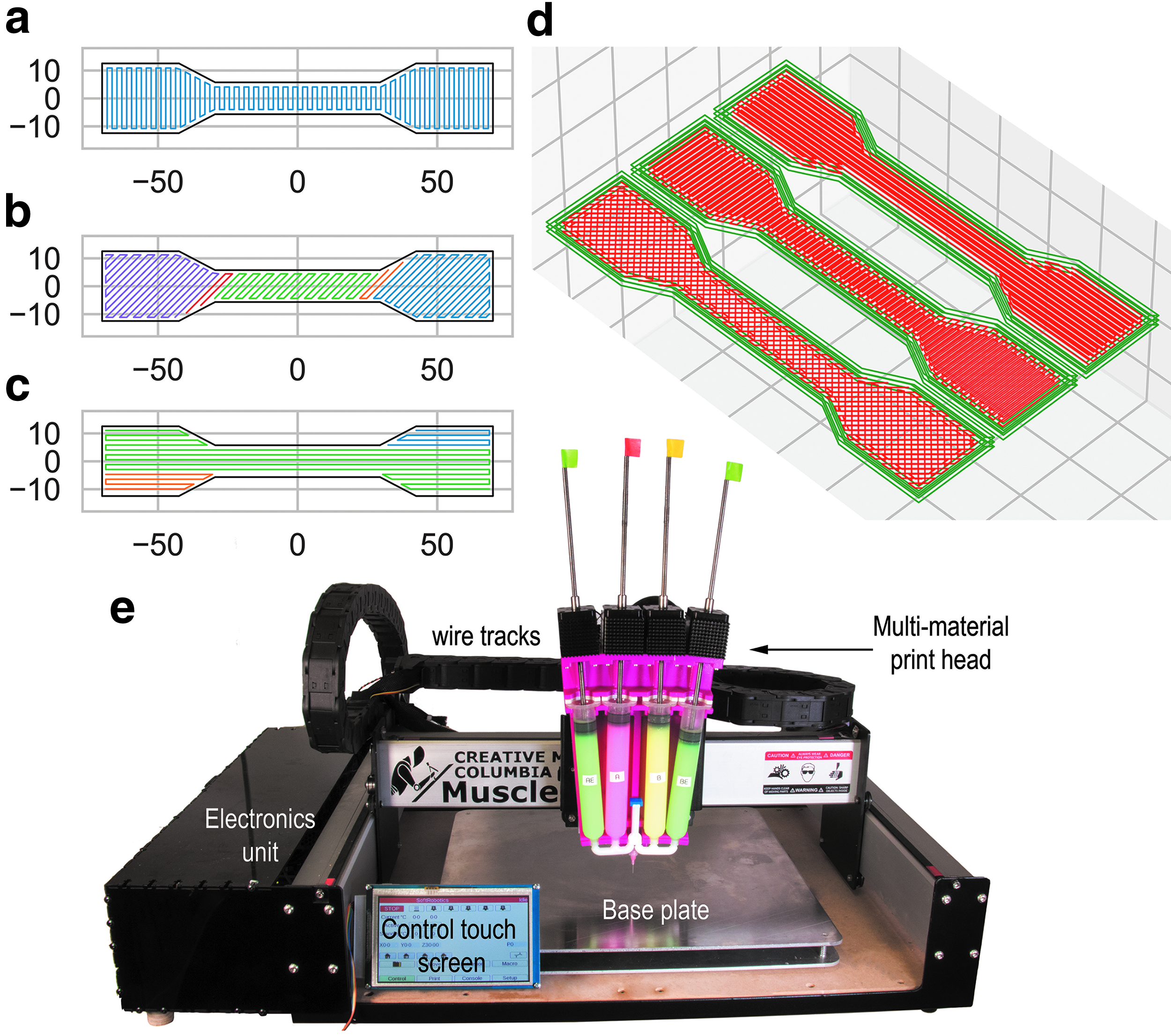
The developed 3D printer is shown in Figure 1e. A Shapeoko 3 platform (Carbide 3D, Tarrence, CA) with the working area size of 406 × 406 × 76 mm was used as the gantry for the 3D printer. Four NEMA 23 stepper motors were used for axis movements. A Duet Wi-Fi control board (Duet3D, Peterborough, United Kingdom) was used to control the 3D printer. A 24 V power supply was used. Two 25 × 25 × 1000 mm sized tracks were used for wire tracking. The adjustable bed plate was made using two 457 × 457 × 4 mm aluminum sheets balanced through compression springs.
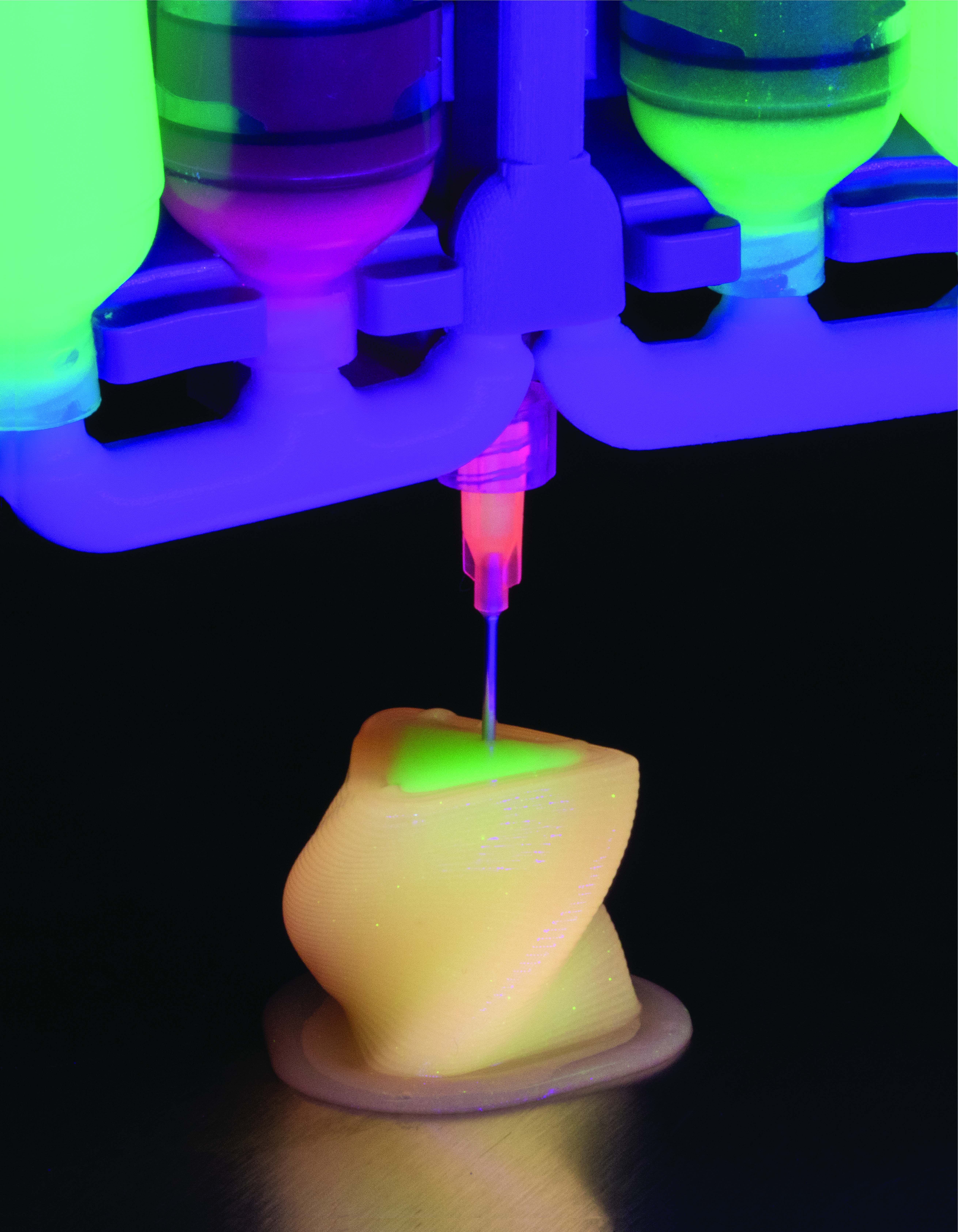
The main idea behind this 3D printer is automation and design freedom in multimaterial silicone composite manufacturing. Thus, following the lessons learned from our previous study, 34 the focus has been spotted on developing a multimaterial print head (Fig. 2a) with passive mixer (Fig. 2e). The latter would allow storing the raw components of the two-part silicone in separate syringes and mixing them only during 3D printing inside the passive mixer. The developed system consists of four syringes and a single passive mixer; the mixer design is discussed in detail later. This print head design allows for the 3D printing of up to three different two-part silicone-based materials in a single print job, for instance, the muscle (silicone/ethanol composite 34 ), the skin (silicone rubber 6 ), and the conductive silicone composite (for Joule heating 36 or sensing). Switching between the materials is possible through an intermediate purging stage. The print head was 3D-printed on the Stratasys J750 (Stratasys, Rehovot, Israel) using hard acrylic material. The tubes and the mixer parts were 3D-printed on the Stratasys J750 machine using the FLX9795-dm material (hardness: Shore A 95). Other print head parts were 3D-printed using Vero material. After 3D printing, the support material was thoroughly removed using the Desktop Water-Jet machine (model OWJ-01US; Stratasys, Israel). The raw data on the 3D printer design, hardware, and software are provided in the Data Availability section of the article.

Multimaterial print head design and functionality:
Rheological properties testing
The rheological measurements were performed on the Bohlin Gemini rheometer from Malvern Instruments (Malvern, Worcestershire, United Kingdom). The shear stress was measured as the shear rate increased linearly from 0.1 to 100 1/s. The materials viscosity η was determined using the following equation:
where τ is the shear stress [Pa] and γ is the shear rate [1/s]. For each experiment, a liquid specimen of 0.1 mL was placed on the testing plate. The gap of 150 μm between the rheometer parallel plates (25 mm in diameter) was maintained during the experiment.
Mechanical testing
The mechanical (tensile) tests were performed on the Instron 5569A Table Mounted Materials Testing System (Instron, Norwood, MA), equipped with a load cell with the maximum capacity of 50 kN, using the Instron BlueHill software. The specimen shape and dimensions were chosen according to the ASTM D-412 standard (Standard Test Methods for Vulcanized Rubber and Thermoplastic Elastomers-Tension). The dumbbell specimens of the Die A standard dimensions were prepared. Cast specimens were prepared by casting the materials into 3D-printed molds, allowing the ASTM D-412 Die A specimen dimensions. The molds were 3D-printed on the uPrint machine (Stratasys, MN) using ABS (acrylonitrile butadiene styrene) material. The 3D-printed specimens were fabricated using the developed 3D printer in the along, across, and crisscross print design modalities (Fig. 1a–d). The strain rate at each experiment was 500 mm/min. Four specimens were tested for each test batch.
Results
Print head design
The design of the multimaterial print head included the considerations of size, ease of mounting, and connectivity to multiple syringes, capacity for multiple use, and the time and quality of mixing by the passive mixer. The design consists of four different syringes (65 mL syringes; Fig. 2a–c) arranged in a row, which are connected to the mixer through three-way tubes (Fig. 2a). The mixer is positioned in the middle between the syringes, so that two syringes are on its right, and two on its left.
Each pair of syringes share one tube, so that in total four syringes are connected to the mixer through two separate tubes (Fig. 2b). The mixer consists of a flow chamber and two cores (Fig. 2e). The flow chamber is a bi-channel unit open at five points: three at the bottom and two at the top. At the bottom, two openings lead to the tubes, which, as described earlier, are connected to syringes; the third opening is connected to a syringe tip for extrusion of the mixed material. The two top openings are designed to host two passive mixer cores. When the mixer is assembled, the mixing core units are interconnected at a single point close to the top of the mixer. In a single section of the mixer core, there are dual fins opposite one another that wrap around in a spiral shape 180°. This creates two flow passages through multiple sections, which are connected in series. The end of a section and the start of its following section differ by 90° axially. Thus, each time the flow from each passage enters a new section, they are split in half, mixing the two opposing passages.
With n number of sections, in each core the material is mixed 2n−1 times. Empirically, it was determined that for thorough material mixing, each mixer core should have six sections. Ecoflex A and B goes through two mixer cores of n mixing channels, mixing
Print head height adjustment
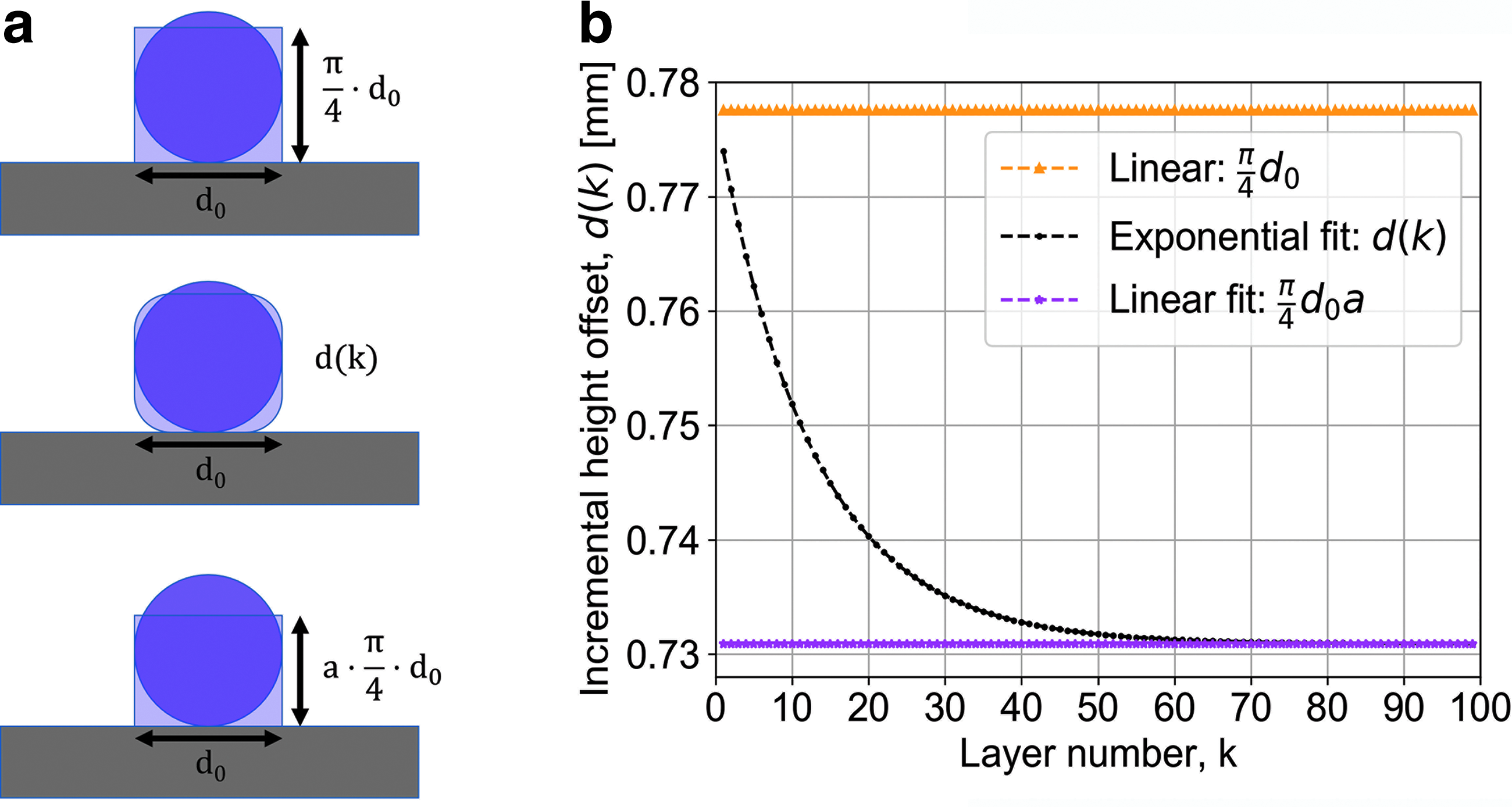
To print a straight line while preventing wavy shape formation, the distance between the print head tip and the previous layer (i.e., print head height offset, z) should be adjusted. Thus, the first (base) layer (k = 0) should be printed at a distance just above the base plate (z = 0). For each next layer, the print head should be raised to a certain incremental height offset d(k), corresponding to the height of the previous printed layer. Ideally, the d(k) value would be equal to the print head tip diameter d0; then, the total print head offset z would equal z = d0·k. However, silicone rubber is extruded from the print head tip in the form of a curing gel immediately after mixing, thus its dimensions subsequently change from an ideal circle with a print head tip diameter d0, to a shape with different dimensions. In addition, silicone rubber compresses when new layers are built on top of the existing ones. When the just-printed circular shape collapses (Fig. 3a), its width (thickness of the printed layer) is mostly retained (d0), whereas its height and geometrical features change.
Print head height correction for 3D-printing silicone and silicone composites (print head tip diameter of 1 mm):
Preserving the material volume (i.e., area of the printed shape, shown in Fig. 3a) would reveal a rectangle with the height equal to
where d(k) is the incremental print head offset relative to the top of the previous layer, d0 is the print head tip diameter, k is the layer number, and a and b are constants. Figure 3b shows the incremental print head height offset for 100 printed layers given by the exponential fit according to Equation (2) with empirically determined parameters a and b (a = 0.9, b = 0.1) for the 18-gauge syringe tips (d0 = 0.99 mm). Similarly, any silicone-based composite may be 3D-printed on this machine by empirical adjustment of the a and b parameters. In Figure 3b it may be seen that after about 60 layers, the incremental height offset reaches an asymptotic value of
3D Printing of functional complex-shaped structures
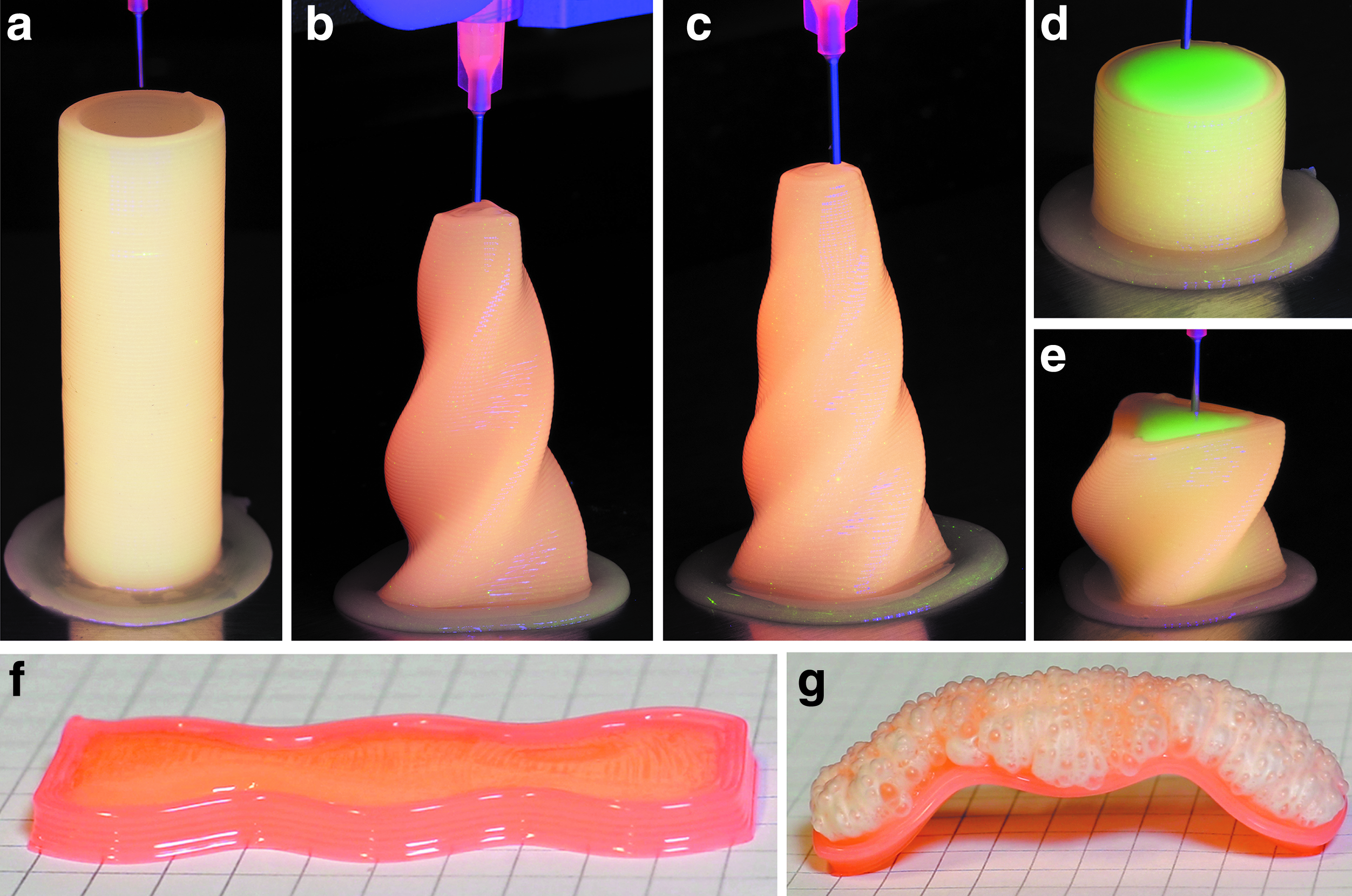
Several specimens were fabricated with various levels of geometrical complexity. We 3D-printed cylindrical and rotating pyramid silicone elastomer specimens, as shown in Figure 4a–c and in Supplementary Video S1. We also 3D-printed the silicone/ethanol composite specimens in the silicone elastomer shell (“skin”), which are demonstrated in Figure 4d–g. A sinewave-shaped silicone/ethanol composite specimen (Fig. 4f) was thermally actuated to bend, as shown in Figure 4g and Supplementary Video S2.
3D-printed silicone and silicone/ethanol composite specimens with various geometrical shapes:
Rheological properties
Results of the assessments of the rheological properties of the silicone rubber and functional silicone/ethanol composite are shown in Figure 5. The study included assessing changes in viscosity of the materials components versus shear rate (Fig. 5a), and mixed (curing) materials viscosity alterations versus time (Fig. 5b). The two-part material components include Part A and Part B for silicone rubber, and Part A + ethanol and Part B + ethanol for the elastomer composite. As shown in Figure 5a, both silicone rubber Part A and Part B demonstrated constant viscosity versus shear rate, namely Newtonian fluid behavior. Viscosity of the silicone Part A was measured at 1.14 Pa·s, whereas that of the silicone Part B was 1.24 Pa·s. Silicone Part A, mixed with ethanol, showed a decrease in viscosity versus shear rate, related to a shear thinning phenomenon. Silicone Part B, mixed with ethanol, showed a slight increase in viscosity at low shear rates, with a subsequent decrease to an almost constant value just <1 Pa·s.

Rheological properties of the silicone and silicone/ethanol composite:
Although viscosity characterization of the raw components is important for designing the syringe-to-mixer stage of the print head, understanding the mixed material viscosity behavior with time is of crucial importance for the mixer design and the entire 3D-printing process. Figure 5b shows an increase in viscosity with time for both mixed silicone rubber and silicone/ethanol composite (20 vol.% ethanol). This increase may be attributed to the curing process, starting immediately after mixing of the A and B (for silicone rubber), and A + ethanol and B (for silicone/ethanol composite) components. The initial mixed viscosity value for both materials is about 3.79 Pa·s. After only 10 s the viscosity value of silicone rubber starts increasing dramatically, and reaches 40 Pa·s by just 75 s. Similar behavior, but with a significantly delayed viscosity increase, was obtained for the silicone/ethanol composite, which reaches the viscosity value of 40 Pa·s after about 215 s.
The practical importance of these results is in estimating the time available for mixing and printing (extrusion from the print head tip) of each new material volume fed into the mixer: <1 minute for silicone rubber, whereas for the silicone/ethanol composite it measures <3.3 minutes. Using inline mixer allows mixing always only a small amount of raw materials, leaving the remaining material stock in the syringes unaffected. When a new portion of raw materials is fed into the mixer, the materials intermix and start curing. Extruding the mixed material in the aforementioned times will prevent material solidification and jamming inside the mixer and allow continuous multimaterial 3D printing of both small and big objects. When switching between materials is required, or when the print job is finished, any material residue may be purged from the nozzle, thus preventing its curing inside the mixer. To allow implementation of this method, a 3D-printing process was designed for each type of material by adjusting the G-code and motor speed, and controlling the plunger advancement inside the syringes with raw components.
Mechanical properties
The mechanical properties of the 3D-printed materials as a function of printing advancement mode were evaluated. Three 3D-print design modalities were implemented: printing across the specimen, along the specimen, and crisscross throughout the specimen (Fig. 1). The results, summarized in Figure 6, show representative stress–strain curves of the silicone rubber and silicone/ethanol composites, as well as average measured tensile force and strain, and modulus at 100% strain for specimens with different print design modalities. Figure 6a and c show that cast silicone rubber exhibits a combination of both high strain and high force (and stress), whereas 3D-printed specimens demonstrate a trade-off in stress or strain as a function of the print design modality. The cast specimens showed a tensile force of about 23.6 N and strain of about 558%. Silicone specimens printed “along” showed only about 16.9 N, but exhibited a relatively high strain of about 500%. Specimens printed “across” showed lower strains (about 445%), but higher tensile force of about 22.8 N. Slightly higher force (23.6 N) and strain (473%) were exhibited by specimens with the crisscross print modality. The results demonstrate anisotropy in tensile properties of the 3D-printed silicone rubber specimens. Figure 6e shows average modulus (M100-modulus at 100% strain) values of the silicone rubber specimens with various print design modalities. It can be seen that the modulus is significantly higher for the 3D-printed specimens (>85 kPa) than for the cast ones (about 56 kPa). The highest modulus, of about 105 kPa, was obtained for specimens with the crisscross printing modality.
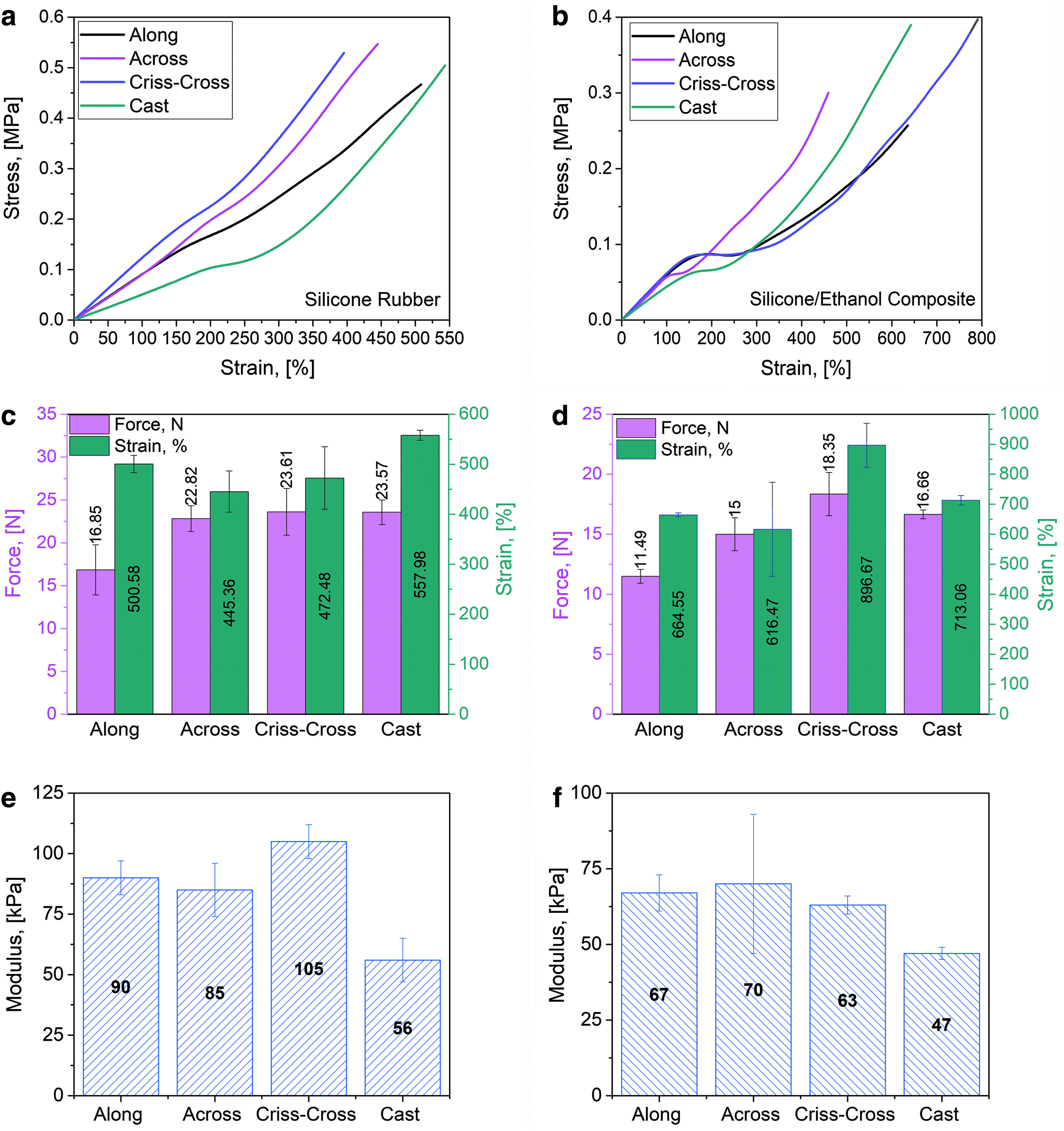
Mechanical properties of the cast and 3D-printed silicone-based materials with various print design modalities (along, across, and crisscross):
Ren et al. 38 showed an anisotropic effect of the tensile stress applied parallel and perpendicular to the monodomain liquid crystal elastomer 39 (LCE) director (an axis that determines the longer range order of the LCE) on the stress–strain behavior. The structure of the LCE determined the value of its modulus: for samples stretched parallel to the director, it was eight times higher than for those stretched perpendicularly to the director, and three times higher than those with polydomain LCE. Owing to their unique properties, 40 LCEs, similar to the silicone/ethanol composite, are used as thermomechanical soft actuators.41–43 Their stress–strain behavior includes three distinct regions: linear elastic, nonelastic reversible, and nonelastic partially irreversible.44,45 The nonelastic reversible region refers to the plateau part of the curves, where large strains are obtained with minimal increase in stress. 40 In LCEs, the nonelastic reversible region is attributed to the polydomain to monodomain (P–M) transition. 46
In this study, the silicone/ethanol composites showed three-regime stress–strain behavior, as opposed to the silicone rubber, for which the linear elastic region was followed by the nonelastic partially irreversible region, where the strain increases significantly with stress. These differences may be explained by the higher cross-linking density of silicone rubber as compared with that of the silicone/ethanol composite. It was shown 46 that for the higher cross-linking densities, LCEs have shorter plateau regions, smaller elongations, and higher modulus values. Figure 6 reflects similar observations for our materials: silicone rubber specimens show almost no plateau, exhibit smaller strains, and have higher modulus values, as compared with the silicone/ethanol composites. It can be seen that the plateau region of the silicone/ethanol composite differs with print design modality, with “across” having the shortest, and “crisscross” the longest. Additional studies should be carried out to investigate the relations between print design modalities, final material chemistry, microstructure, and mechanical properties of the silicone/ethanol composites.
Conclusions
In this study, we designed and developed a silicone composite 3D printer, based on the material properties study. Both the software and the hardware aspects have been considered. The developed 3D printer is controlled by G-code, adjustable for printing of various two-part platinum-catalyzed silicone composites by using an empirically determined formula. The 3D printer uses an inline passive mixer, specially designed based on the evaluation of the materials' rheological properties. The 3D printer has a workspace area of 40.6 × 40.6 × 76.2 cm, and is capable of 3D printing up to three different silicone composites in a single print job. We demonstrated fully automated 3D printing of a silicone/ethanol composite actuator and its encapsulating silicone rubber skin in a variety of geometrical shapes. The mechanical properties of the 3D-printed materials were evaluated at different printing modalities (along the specimen, across, and crisscross) and compared with the cast counterparts. Anisotropy in mechanical properties was obtained for the 3D-printed specimens, allowing for the tailoring of the final part's properties at the design stage by choosing an appropriate 3D-printing direction/modality.
Data Availability
The raw data required to reproduce these findings are available to download from https://github.com/boxiXia/Soft-Muscle-Printing
Footnotes
References
Supplementary Material
Please find the following supplemental material available below.
For Open Access articles published under a Creative Commons License, all supplemental material carries the same license as the article it is associated with.
For non-Open Access articles published, all supplemental material carries a non-exclusive license, and permission requests for re-use of supplemental material or any part of supplemental material shall be sent directly to the copyright owner as specified in the copyright notice associated with the article.