




Abstract
Underperformed interfacial bond and anisotropic properties are often observed in three-dimensional-printed concrete, where the printing pattern is unidirectional. Such issues could be potentially alleviated by replicating microstructures of natural materials or applying different architectures, where printed layers are arranged into unique and unconventional patterns. Furthermore, the quest to develop printing methods for highly complex or self-support concrete architecture could benefit from these nature-inspired patterns. In this work, the influences of different architectural arrangements of layers on mechanical properties of hardened concrete on compressive and flexural strengths are investigated. Specifically, unidirectional (0°), cross-ply (0°/90°), quasi-isotropic (0°/ ± 45°/90°), and helicoidal patterns (with pitch angles of 10°, 20°, and 30°) are used to create unidirectional, bidirectional, and multidirectional layers in printed objects without and with 0.75% by volume of 6 mm-long steel fibers. The experimental results demonstrate considerable improvements in the flexural strengths of nontraditional specimens without steel fibers over the unidirectional control with a few exceptions. Among investigated patterns, the quasi-isotropic demonstrates significant influences in both compressive and flexural responses of printed concrete samples without steel fibers. The addition of steel fibers leads to noticeable improvement on both compressive and flexural strengths of samples in any pattern compared with their counterparts without fibers. Besides, the inclusion of steel fibers into unconventional layups (cross-ply, quasi-isotropic, and helicoidal patterns) leads to the alleviation of directional dependence of mechanical properties, which is a limitation of the unidirectional samples with fibers. Of all helicoidal patterns, the one with a 10°-angle layup is shown to be more beneficial to the flexural strength enhancement and damage resistance in bending. X-ray microcomputed tomography measurements are performed to visualize the direction and distribution of fibers.
Introduction
Although there has been rapid growth in three-dimensional (3D) concrete printing, it is still in relatively early stages of development with many issues and challenges that need to be comprehensively researched and solved. Undoubtedly, one of the problematic issues is the directional dependence of mechanical properties1–11 associated with the extrusion-based process and weak interfacial bonding. 5 The behavior is obviously inherent and unpreventable in the layer-by-layer deposition process 11 ; however, practical solutions can be investigated and applied to strengthen the vulnerability of the interface and alleviate anisotropic properties.
The bond mechanism between new and old concrete interfaces experiences three stages, namely adhesion, friction, and mechanical interlock. 12 In particular, adhesion resistance of the interface,13,14 which is considered a chemical bond, is mainly dependent on physical and chemical characteristics of mixture compositions. 15 Following that, frictional mechanisms acting against slip at the interface appear right after the adhesion mechanism disappears. 13 Finally, after the adhesion and friction action, mechanical interlock acts to boost bond strength depending on the roughness of the surface (e.g., size and shape of aggregate particles, surface texture).12,14 It is confirmed that apart from adhesion resistance, bond capacity is fundamentally dependent on mechanical interlocking,14,15 which contributes extra resistance for interfacial bond. Similarly, bond characteristics between two layers in printed concrete have these mechanisms, and in this case, mechanical interlock primarily depends on interface configurations.
There are several studies in 3D printing investigating influencing factors on adhesion resistance of the interface between layers. Nerella et al. 4 asserted that material ingredients are a determinant of adhesion resistance of the interface; meanwhile, Sanjayan et al. 5 identified the effect of the level of surface moisture between layers on the development of interface bond capacity. In addition, Zareiyan and Khoshnevis 16 investigated the effectiveness of interlocking configurations at the interface using an experimental protocol that simulated the layer-by-layer fabrication process. The testing result revealed that interlocking with a depth of 12.7 mm could lead to an increase in bond strength by 26% for splitting tests. Based on the literature review, there are two fundamental mechanisms of bond strength at the interlayer of printed components, including the following: (1) adhesion mechanism, which can be optimized by designing appropriate mixture compositions, reducing time interval or properly selecting the printing parameters, and so on; and (2) interlocking mechanism by introducing new interface configurations.
To evaluate bond performance for old-to-new concrete interfaces, bond test methods can be categorized into four main groups based on existing reviews,12,17 including shear test with different test protocols (direct shear and slant shear)15,18,19; indirect tensile test, known as flexural test 20 and prismatic or cylindrical splitting tests19,21,22; direct tensile test 17 ; and pull-out test. 23 It is worth noting that there is no reasonable concordance between the results obtained from different test methods; therefore, it is not possible to compare them.12,17 Momayez et al. 12 stated that no matter what bond test is selected, the most important thing is that the selected method should represent the state of stress of structures under a specific loading scenario in a certain application. In the 3D printing technique, three prevalent test methods used to determine the interface bond strength of printed elements include direct tensile test,1,5,24,25 splitting tensile test,3,16,26 and flexural strength test.4,27 Other studies experimentally observe the substantial discrepancy in flexural strengths between different directions due to the poor performance of the interface.3,5,6,9
Enhancing the performance of engineering materials by replicating microstructures of biological materials28–31 (Fig. 1) or applying different architectural patterns32,33 has been of significant interest recently, which introduces an inspiring approach to develop novel construction materials. 29 Some typical architectural patterns, namely cross-ply, quasi-isotropic, and helicoidal layups, are widely applied in the fabrication of composite materials in laminated object manufacturing and additive manufacturing. These layup methods generate different internal structures of composite materials, resulting in different mechanical responses over the unidirectional pattern. The unidirectional layup is considered a cause for anisotropic behavior,34,35 especially in bending response because of a considerable difference in strengths between layer direction and transverse direction. 36 Quasi-isotropic architecture is the most used design for fabricating composite materials in the aerospace industry. 37
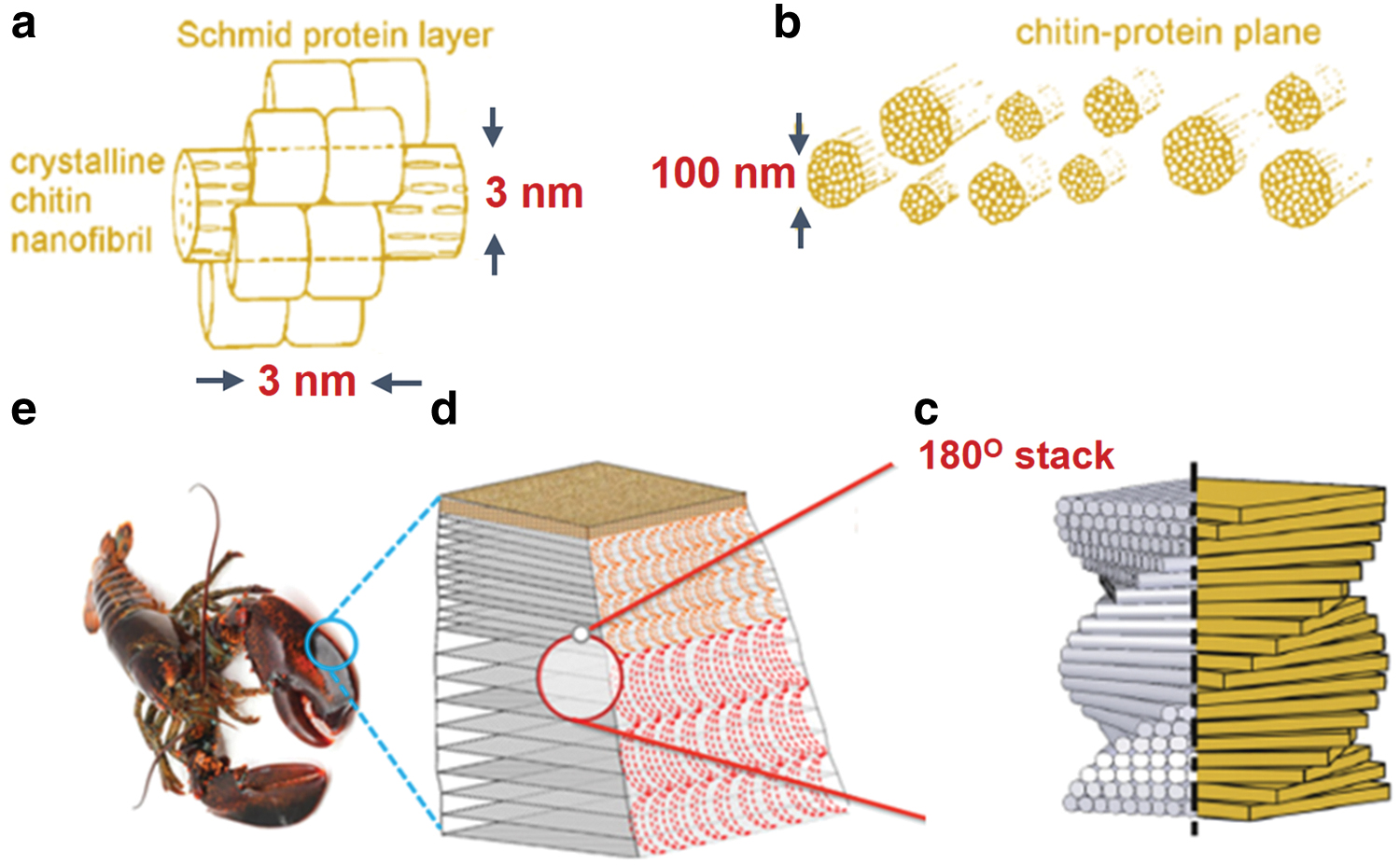
Hierarchical microstructure of the cuticle of the lobster (Homarus americanus; based on existing studies38,39,45). Here, nanofibrils with few nanometers in diameter
Recently, the Bouligand structures (helicoidal sequences), as presented in Figure 1, have become more and more prevalent, especially in composite materials. The Bouligand structures found in biological materials (Homarus americanus—American lobster) are characterized by periodically stacking layers of fibrous materials into a helicoidal arrangement with a pitch angle of rotation deviating from their lower adjacent layer.35,38 Hierarchical arrangement in the exoskeleton of Homarus americanus (Fig. 1c) is formed from chitin/protein planes (Fig. 1b) gradually stacked about their normal direction in a rotation of 180°, which include a network of chitin/protein fibers. 39 Each fiber (Fig. 1b) has a diameter of about 50–250 nm consisting of a cluster of fibrils with the diameter of about 2–5 nm and the length of about 300 nm for each fibril (Fig. 1a). The Bouligand structure is proven as an ideal hierarchical model with exceptional structural performance, 38 and thus, it is considered an appropriate pattern for reproduction in man-made materials. 40 A noticeable feature of helicoidal architecture is that its helicoidal arrangement governs crack into a twisted path, thereby facilitating the ability of the material to resist fracture and delay disastrous failures, 41 and might also lead to an improvement in strength. 38 For the construction field, there are still limited studies investigating the changes of different internal architectures of cement-based materials on mechanical behavior. Moini et al. 42 applied helicoidal architectures to create different internal textures in concrete structures at the macroscale to improve mechanical performance.
It is reported that the architectural patterns adopted offered quasibrittle damage, strengthened fracture, and damage modes, and had a distinctive load/displacement diagram. Hambach and Volkmer 43 investigated the effect of different print path directions on mechanical performance, reporting that a dramatic enhancement is achieved in flexural strength of specimens (reinforced with 1% volume fraction of carbon fibers) printed in a parallel shape. The latest study published by Li et al. 44 applied different printing paths to explore the confinement effect of microcable reinforcement in printed objects. It is revealed that continuous steel cables lead to a significant increase in mechanical properties of hardened concrete in terms of compressive and tensile responses under certain printing patterns. The unidirectional printing path has been the most common pattern used in most studies to test the material properties of printed concrete components.
The current research investigates the effect of different architectural patterns on compressive and flexural properties of printable concrete with and without steel fibers. The experimental program is divided into two different sections. The first section includes three common patterns selected for research, including unidirectional (0°), cross-ply (0°/90°), and quasi-isotropic patterns (0°/ ± 45°/90°). 37 The unidirectional control is the most conventional pattern used in 3D concrete printing. Meanwhile, the cross-ply and quasi-isotropic architectures selected in the current research are inspired by laminated composite structures37,38,46 and layer-by-layer deposited composites. 47 In the second section, printed concrete is designed into helicoidal structures (Homarus americanus)38,48 with three different pitch angles of 10°, 20°, and 30°, which can be called helicoidal 1, 2, and 3, respectively. The reason for investigating different rotational angles is because it is an important factor affecting material performance in helicoidal layups. The main objective of this work is to explore the capacity of enhancing interface performance under flexural tests and the possibility of alleviating the degree of anisotropic mechanical properties evaluated by coefficients of variation (CVs). 4 It also provides the experimental results and discussions for compressive strengths. The visualization of fiber orientations in each pattern is obtained by X-ray microcomputed tomography (CT).
Experimental Program
Material preparation and specimen fabrication process
Material preparation
The proportion of mixture ingredients used in the current study is detailed in Table 1. The mixture design is developed by modifying ultrahigh-performance steel fiber-reinforced concrete, which is initially designed by Wu et al. for the conventional casting process. 49 The mixture comprises three different binders, including general-purpose cement, silica fume, and ground granulated blast-furnace slag, with chemical compositions specified in Table 2. Sand, which is the largest aggregate with a particle size lower than 1 mm, is mixed with a weight ratio of 1:1 to the binders. The water/cement ratio is 0.377, which remains unchanged from the original mix. Preliminary investigations are implemented to determine the appropriate dosage of chemical liquids, including superplasticizer and retarder to meet the desired buildability.
Mixture Compositions
GP, general-purpose.
Chemical Compositions of General-Purpose Cement, Silica Fume, and Ground Slag
There are two different mixtures used in this study, which are without and with steel fibers. Steel fibers of 6 mm length with 0.75% by volume are selected to investigate its effect on mechanical properties of hardened concrete printed in different architectural patterns. This selection in terms of length and amount of fibers is based on a preliminary investigation, 50 which demonstrates a noticeable enhancement on both the compressive and flexural responses. The properties of the steel fibers are presented in Table 3.
Physical and Mechanical Properties of Steel Fibers
The high-performance printing concrete is mixed using a mixer of a 20-L capacity. Initially, all powder ingredients are premixed for 5 min to attain a consistent distribution of all materials in the dry mix. Then two-thirds of the water and the entire amount of superplasticizer and retarder are blended and gradually added into the mixture for 1 min before adding the rest of the water. The wet mixing process lasts for 12 min to obtain a uniform and flowable paste, and then, steel fibers are added and mixed for an extra 3 min.
Specimen fabrication process
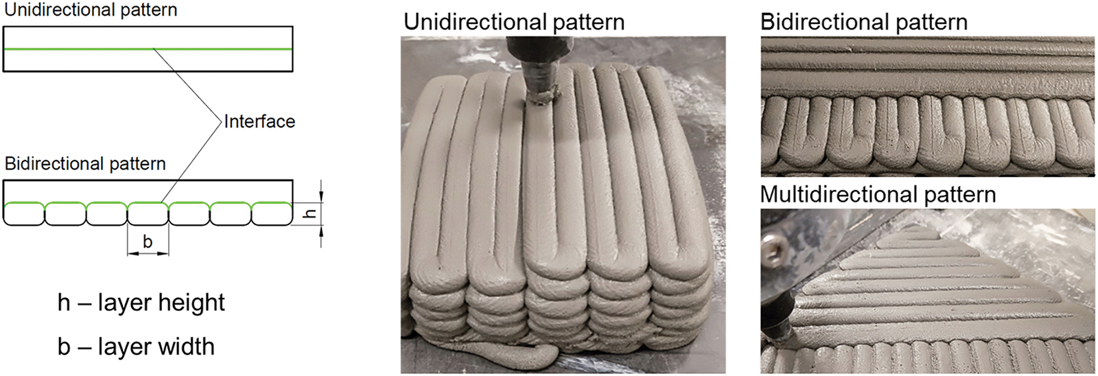
A printer, operating as a robotic arm, is used to print samples with a 9-mm-diameter nozzle at a printing speed of 25 mm/s. The printer can rotate 360° and reach 1.828 m from the center in the horizontal direction, and the maximum movement distance of the arm that can be reached in the vertical direction is 1.150 m. The width of each layer is automatically calculated as equal to 10.8 mm based on the nozzle diameter, and the height of each layer is 6 mm. Mixtures are mixed to fabricate concrete blocks following six different printing patterns, as shown in Figure 2. Each pattern has three printed blocks with different sizes, in which block 1 has the dimension of 315 × 162 × 42 mm (length × width × height); block 2 is 227 × 184 × 60 mm; and block 3 is 160 × 125 × 125 mm, as shown in Figure 3. The dimensions of these blocks are based on the capacity of the extruder as well as desired dimensions and number of specimens for compressive and flexural strength tests. A total of 36 printed blocks are stored in laboratory conditions, and the process of cutting these samples is conducted several days before the 28-day testing date.
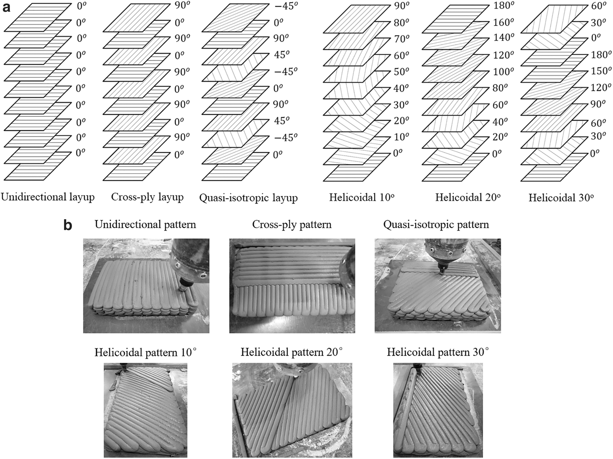
Schematic of different printing patterns
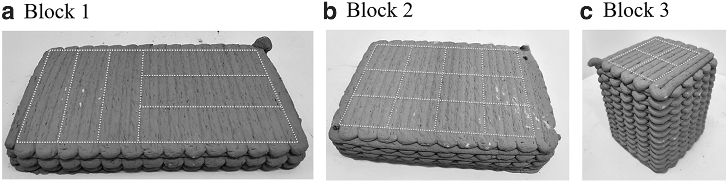
Three different printed blocks with different dimensions: 315 × 162 × 42 mm
Specimens for compressive and flexural strength tests are cut from the concrete blocks by a water-cooled sawing machine. Twelve 50 mm cubic samples are extracted from block 2 for the compression test in three directions Z, Y, and X. Specimens for the three-point bending test with dimensions of around 40 × 40 × 160 mm are cut from block 1 for testing in directions Z1 and Z2 and from block 3 for testing in direction X. After being cut, the specimens are polished by a stone polisher machine to make the surfaces flat and parallel.
Mechanical property determination
Compressive strength tests of the 50 mm cubic specimens are performed by a 1000 kN MTS universal testing machine at a loading rate of 900 N/s in accordance with ASTM C109. 51 The compressive test specimens are tested in three directions Z, Y, and X, which are defined according to the direction of the first layer. These are the vertical buildup direction, the printing direction of the first layer, and the horizontal expanding direction of the first layer, respectively, as illustrated in Figure 4. The loading directions are defined according to the direction of the first layer so that each type of printed block (1, 2, or 3) has the same direction of the first layer among patterns.
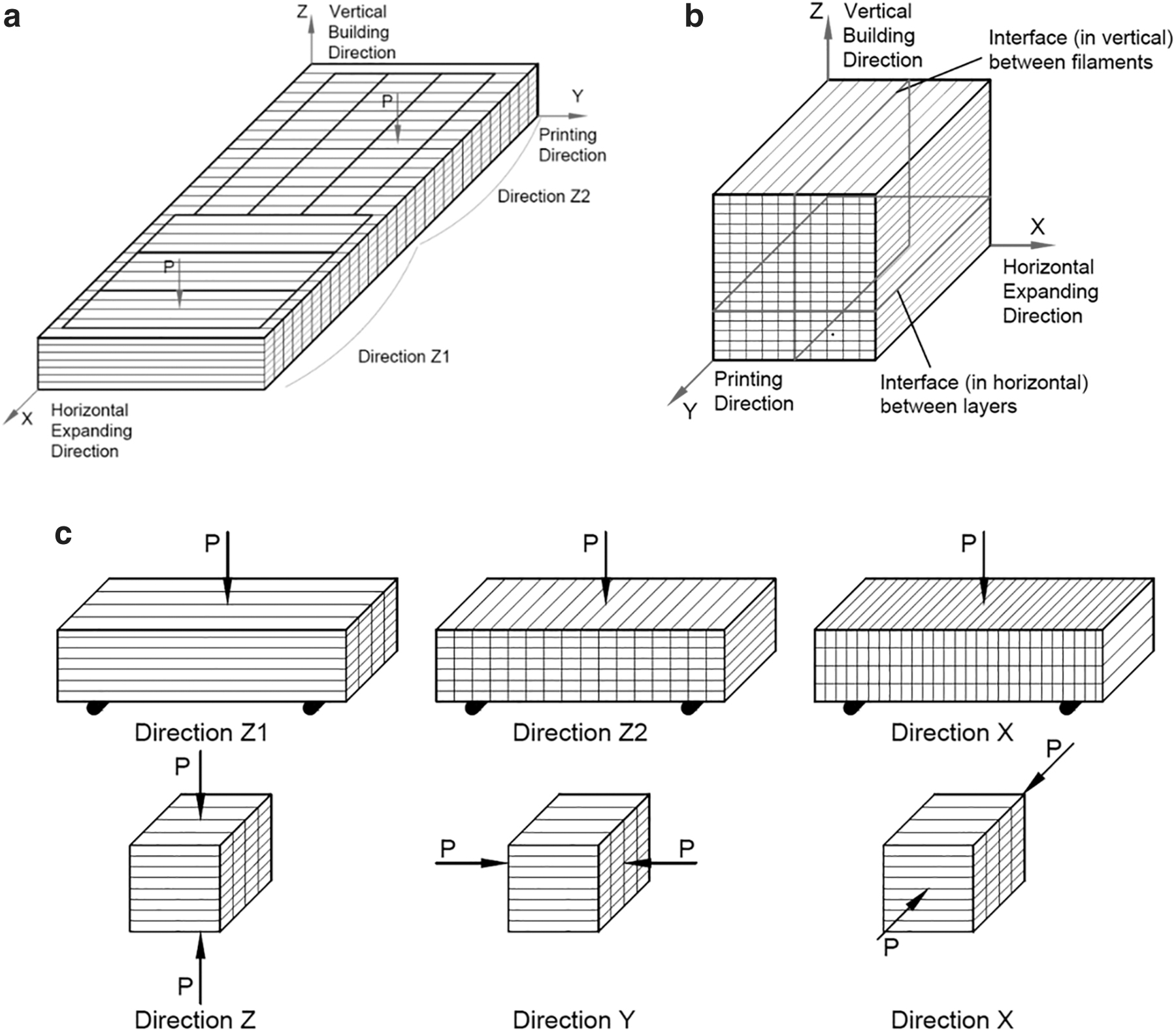
Flexural responses are determined by three-point bending tests under force-controlled loading mode at a rate of 20 N/s, in compliance with ASTM C348. 52 Bending tests are conducted in three directions, namely Z1, Z2, and X, which are also defined according to the direction of the first layer. Specifically, in direction Z1, the longitudinal axis of the beam is parallel to the printing direction and is tested to the normal direction of the layers. In direction Z2, the longitudinal axis of the beam is perpendicular to the printing direction and is tested in a normal direction to the layers. Also, in direction X, the longitudinal axis of the beam is parallel to the vertical buildup direction and is tested in a transverse direction to the layers, as shown in Figure 4. Bending tests in directions Z2 and X in the unidirectional layup could reflect the performance of the interface between the strips (the vertical interface) and between the layers (the horizontal interface), respectively, as described in Figure 4. Likewise, for the cross-ply, quasi-isotropic, and helicoidal patterns, samples tested at each direction have the direction of the first layer identical to their unidirectional counterparts. Each obtained strength in this article is an average value of three specimens.
X-ray micro-CT measurement
3D visualization of internal structures of printed objects, particularly the orientation and distribution of steel fibers, is acquired by conducting a micro-CT examination, which is a noninvasive testing method. Scanning is set with a tube voltage of 175 kV and a tube current of 110 μA. The 50 mm cubic sample is located at a distance from the X-ray generator corresponding to a resolution of 40 μm. Only part of the sample in the vertical direction is scanned to reduce scanning time. The specimen is rotated over 360°, while X-radiation is generated by an X-ray tube passing through the object and detected by a detector to convert the attenuation of radiation into digital images, 53 which are recorded by a computer connected to the micro-CT system. As a result, 1500 projections are captured at different angular positions with a scan timing of 500 ms per image; the total scan period lasts ∼50 min for each sample. Phoenix datos|x CT software for automatic reconstruction and volumetric data acquisition is utilized to reconstruct the set of two-dimensional (2D) projection images into a 3D volumetric data set. After that, Volume Graphics VGStudio MAX 3.0 software is used to analyze and visualize the deviation angle of fiber orientation from the reference orientation, which is parallel to the orientation of the first layer.
Results and Discussion
Effect of unidirectional, cross-ply, and quasi-isotropic patterns
This section presents the compressive and flexural test results of hardened concrete arranged into unidirectional, cross-ply, and quasi-isotropic patterns. It also displays the deviation angle of steel fibers relative to the orientation of the first layer, which is obtained from micro-CT measurement.
Compressive strength test
In general, the compressive strengths of fiber-reinforced specimens (97–120 MPa) are higher than those without fibers (86–107 MPa), as shown in Figure 5. For specimens without fibers (Fig. 5a), cross-ply and quasi-isotropic patterns increase the compressive strengths in directions Z and Y, but remain nearly unchanged in direction X in comparison with the unidirectional control. More specifically, while the compressive strengths of cross-ply specimens are 7% and 21% higher in directions Z and Y, those of quasi-isotropic specimens increase by 23% and 6%, respectively.
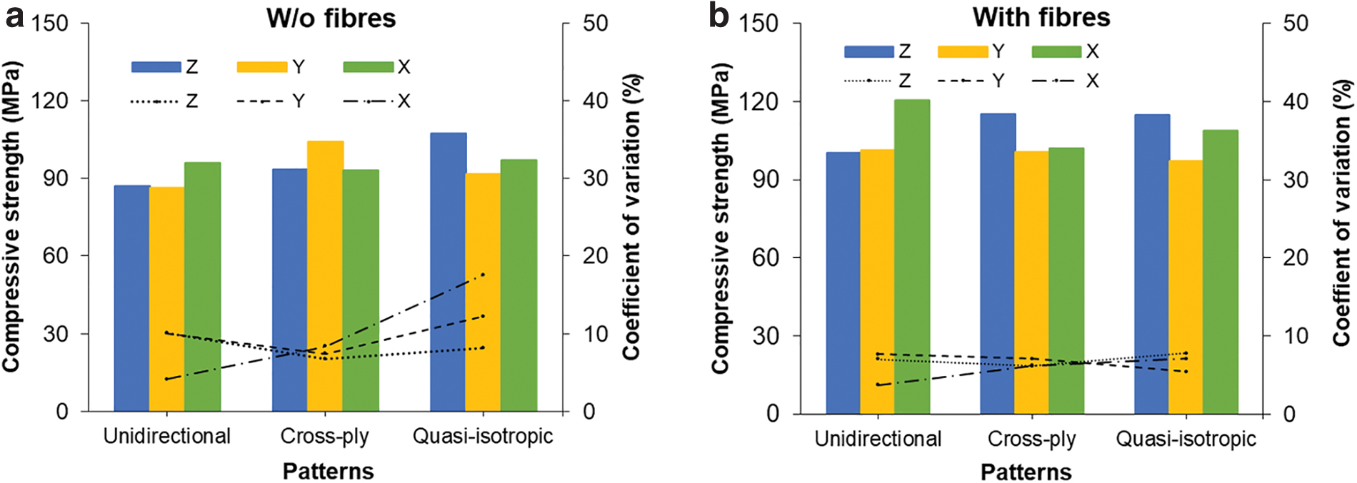
Compressive strengths of all specimens printed without fibers
Changes in the internal architecture of hardened concrete due to multiple directions of the matrix are the reason for the higher resistance against compression load for samples without fibers. More specifically, various directions of layers could lead to stronger connections between layers and within the printed concrete, resulting in the enhanced compressive strengths of cross-ply and quasi-isotropic samples without fibers. There is no specific trend for the compressive strengths of samples without fibers between directions, meaning there is no direction predominant for all patterns. For fiber-reinforced specimens (Fig. 5b), the compressive strengths in direction Z (115 MPa) in cross-ply and quasi-isotropic layups increase by 15% when compared with that of the control pattern (100 MPa); meanwhile, values in directions Y and X are lower. The highest compressive strengths in direction Z in these patterns, which is not observed in the unidirectional control, could be attributed to a firm connection within the printed sample resulting from each filament connected to multiple filaments caused by bidirectional and multidirectional arrangements.
Improvements in the compressive strengths of specimens with fibers over their counterparts without fibers are found, increasing by 6–26% (except for cross-ply samples in direction Y) (Fig. 5). Steel fibers have the most beneficial influence on the compressive strengths of unidirectional specimens in any direction. The CVs for the strengths of fiber-reinforced samples range from 3.7% to 7.8%, while the values for samples without fibers are between 4.2% and 17.6%. It should be noted that CVs in Figure 5 show the dispersion of compressive strengths between different samples tested in a specific direction of a pattern.
Figure 6 demonstrates the average compressive strength of all directions in each pattern and the corresponding CV. It is worth noting that CVs in Figure 6 show the dispersion of compressive strengths between different directions in each pattern. Interestingly, the average compressive strength of all directions of specimens without fibers slightly increases in order of unidirectional, cross-ply, and quasi-isotropic patterns (90, 97, and 99 MPa, respectively). Furthermore, the results for fiber-reinforced specimens are almost the same among patterns (Fig. 6), at ∼107 MPa. Of all patterns, the unidirectional pattern with steel fibers has the highest CV, while its counterpart without fibers has the lowest value. This reflects that a single direction of fibers leads to a higher degree of anisotropy for the compressive strength tests in the unidirectional pattern.
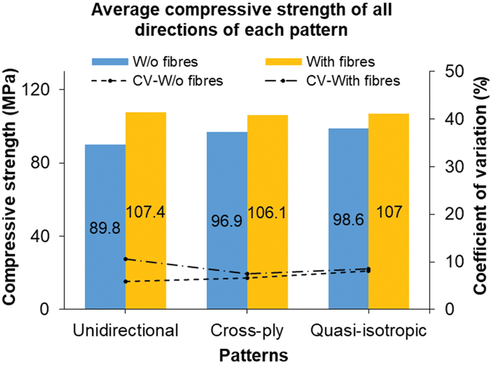
Average compressive strength of all directions of each pattern on the bar charts (left-hand side axis) and corresponding coefficient of variation on the line charts (right-hand side axis). Color images are available online.
Flexural strength test
In general, the flexural strengths of specimens with and without fibers in any pattern are the highest in direction Z1, and values for directions Z2 and X are lower, as shown in Figure 7. The results in the unidirectional pattern are consistent with other studies.1–4,54 The lower flexural strengths in direction Z2 are attributed to the direction of the first layer perpendicular to the length of the beam, which is likely to split under bending load. In the meantime, the strengths in direction X are dependent on bond strength between layers. The highest strengths in direction Z1 relative to those in directions Z2 and X are, in general for all patterns, due to the direction of the first layer parallel to the longitudinal axis of the beam, creating continuous filaments in the stress direction, together with well-compacted material in this direction under extrusion pressure. 1 In cross-ply and quasi-isotropic patterns, the texture of layers of samples tested in direction Z1 is the same as in direction Z2, Figure 8b1 vs. 8b2, and Figure 8c1 vs. 8c2; however, they start with different directions of the first layer. This leads to a substantial discrepancy in the flexural strengths between directions Z1 and Z2; this also reflects the great importance of the direction of the first layer in flexural resistance.
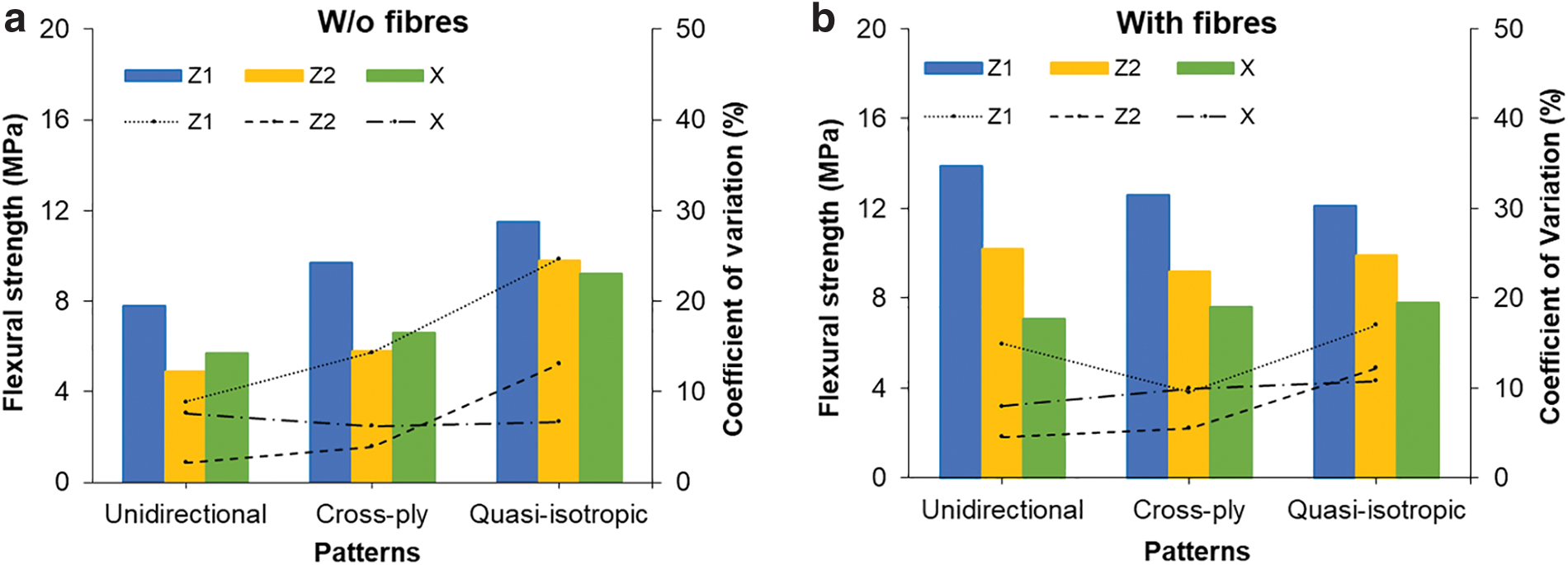
Flexural strengths of all specimens printed without fibers
Figure 7a demonstrates pronounced effects of cross-ply and quasi-isotropic patterns on the flexural strengths of samples without fibers over the unidirectional control in all directions. In direction Z1, the flexural strengths of cross-ply and quasi-isotropic specimens without fibers increase by 24.4% and 47.4%, respectively. In the unidirectional control, all layers are parallel to the centerline of the beam (Fig. 8a1). Meanwhile, cross-ply layup generates two directions of layers (0° and 90°) in the specimens, resulting in a reduction in the number of layers parallel to the longitudinal axis of the beam tested in direction Z1 (Fig. 8b1). Despite this fact, the flexural strength of cross-ply specimens increases in this direction due to the following reasons. First, the bending capacity of the beam is highly dependent on tensile resistance of the first layer, which is along the length of the beam in all samples tested in direction Z1. Second, a crack might not propagate through the interface between filaments perpendicular to the longitudinal axis of the beam. Finally, two consecutive layers stacked into two directions perpendicular to each other lead to one filament connected with many others (Fig. 9), resulting in a stronger connection within cross-ply samples, compared with a single direction of layers. Thus, the reduced number of longitudinal layers in cross-ply samples does not necessarily decrease its flexural strength. Regarding the quasi-isotropic pattern, concrete layers are connected in multiple directions (Fig. 8c1), possibly leading to the most solid connection of all studied patterns, which is most likely to boost the bending strength in direction Z1 by 47.4%.
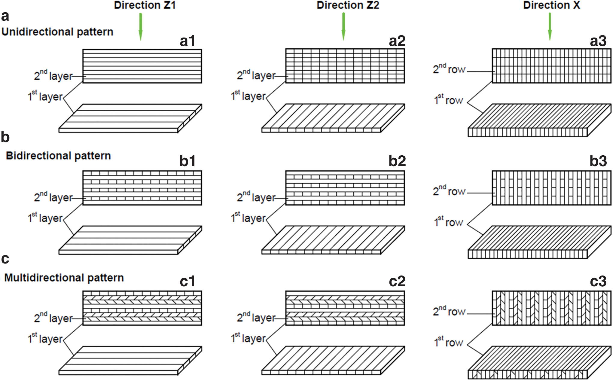
Directions of layers in specimens with unidirectional printing pattern
Layer stack-up in different patterns. Color images are available online.
In direction Z2 (Fig. 7a), an increase of 18.4% and 100% for the flexural strengths of cross-ply and quasi-isotropic specimens without fibers, respectively, is compared with the unidirectional control. It should be recalled that samples tested in direction Z2 in all patterns have the same direction of the first layers, which is perpendicular to the length of the beam. In unidirectional specimens, all layers are perpendicular to the longitudinal axis of the beam (Fig. 8a2), which are susceptible to splitting through the vertical interface between strips. As a result, the lowest flexural strength is observed. However, the cross-ply pattern with layers printed in both directions 0° and 90° leads to the reduced interfacial area and the increasing number of layers along the length of the beam tested in direction Z2 (Fig. 8b2). A change in the vertical interface configuration is the most likely explanation for an increase of 18.4% in the flexural strength in this case. In the meantime, the quasi-isotropic pattern generating multiple directions of layers (0°, −45°, 45°, 90°) in samples leads to a complete change in the interface configuration, where the vertical interface exists only at the first and fifth layers (Fig. 8c2). This results in an impressive increase of 100% in the flexural strength of the quasi-isotropic specimen in direction Z2.
In direction X (Fig. 7a), there are 15.8% and 61.4% increases in the flexural strengths for cross-ply and quasi-isotropic specimens without fibers relative to their unidirectional counterpart, respectively. Unidirectional specimens tested in direction X are susceptible to splitting (Fig. 8a3); thus, the strength is found to be the lowest. In the meantime, the different directions of layers in cross-ply and quasi-isotropic patterns form interlocks between two consecutive layers, as shown in Figure 9. These interlocks are generated by the next layer filling the gap between the filaments of the lower layers, leading to a stronger bond between layers when compared with parallel layers in unidirectional samples. The surface configuration of the horizontal interface becomes undulating instead of almost planar as the unidirectional pattern (Fig. 9). As a result, mechanical interlock action in cross-ply and quasi-isotropic samples can be promoted, thus boosting bond resistance and increasing flexural strengths in direction X. Compared with cross-ply specimens (Fig. 8b3) in direction X, quasi-isotropic counterparts (Fig. 8c3) create more diverse configurations of the interface and stronger interlocking at different directions of a layer (Fig. 9), making it harder to split; therefore, a more pronounced increase is found in bond strength.
The flexural strengths of unidirectional specimens with fibers significantly increase by 78.2%, 108.2%, and 24.6% in directions Z1, Z2, and X, respectively, when compared with their counterparts without fibers (Fig. 7). It is not surprising for samples in direction Z1 because fibers align with the length of the beam, which can carry tensile stresses after the first matrix cracking, thus enhancing the flexural strength. For direction Z2, the 108.2% increase is more than expected because fiber direction is parallel to the vertical interface and perpendicular to the longitudinal axis of the beam. However, when the crack surface does not entirely propagate through the interface, it can be hypothesized that its path can cross fibers, and in this situation, the presence of steel fibers could contribute to enhancing the vertical interface.
The same scenario occurs in direction X, and the increase in flexural strength is also due to this reason. With regard to the cross-ply pattern, the addition of fibers also leads to an enhancement in flexural strengths, increasing by 30%, 58.6%, and 15.2% in directions Z1, Z2, and X relative to those without fibers, respectively (Fig. 7). The observation is understandable for directions Z1 and Z2 because more layers of fibers aligned with the longitudinal axis of the beam, leading to a significant improvement in bending resistance. In the meantime, quasi-isotropic samples reinforced with steel fibers have a slightly higher flexural strength in directions Z1 and Z2, and a bit lower value in direction X, which is governed by the interface bond, when compared with relative samples without fibers.
Although fibers in quasi-isotropic samples are oriented in different directions (0°/ ± 45°/90°), the number of fibers aligning with the length of the beam is limited and insufficient to induce a significant effect on the flexural strengths. From the above discussion, it can be noted that the use of steel fibers has the most significant effect on the unidirectional control, the second on cross-ply specimens, and the least on quasi-isotropic specimens. Steel fibers, in general, also have a more significant influence on samples in directions Z1 and Z2, but little effect in direction X, which is prominently dependent on the bond strength at the horizontal interface.
Figure 7b shows comparisons of the flexural strengths of fiber-reinforced samples in each direction between the studied patterns. It reveals that there is not much difference in the flexural strengths in directions Z2 and X between patterns. The results for direction X are understandable because the strength in this direction is mainly governed by the interfacial bond. Similarly, the flexural strengths in direction Z2 in all patterns are highly dependent on the interfacial bond of the first layer; therefore, different orientations and distributions of steel fibers in these patterns are incapable of creating a significant discrepancy in the flexural strengths between them. In direction Z1, unidirectional control shows the highest flexural strength relative to cross-ply and quasi-isotropic specimens. This observation is also found in another study on continuous carbon fiber-reinforced composites fabricated by the 3D printing method. 47 The obtained result is attributed to a reduction in the number of fiber layers that align with the centerline of the beam in cross-ply and quasi-isotropic specimens. The CVs for the flexural strengths of fiber-reinforced samples range from 4.5% to 17%, while values for samples without fibers vary between 2.2% and 24.7%, as shown in Figure 7.
As mentioned above, the flexural strengths of samples in direction Z1 in each pattern are consistently higher than those in directions Z2 and X for both printed concrete without and with steel fibers (Fig. 7a). It is observed that the flexural strengths of unidirectional and cross-ply samples without fibers in direction Z2 are lower than their counterparts in direction X (Fig. 7a). Meanwhile, the opposite trend is found for those of quasi-isotropic samples without fibers. In the unidirectional pattern, extrusion pressure in vertical direction enables the higher bond strength between layers (direction X) compared with the interfacial bond between strips (direction Z2) with no pressure in the transverse direction. In the cross-ply pattern, the bond strengths in both directions Z2 and X are improved in quite the same rate due to the change in interface configuration and interlocking formation, respectively.
In quasi-isotropic layup, the higher flexural strength in direction Z2 is due to a significantly reduced interface area compared with that in direction X, which is still a real interface regardless of the change in the printing path. For fiber-reinforced samples, cross-ply and quasi-isotropic layups drive fibers into bidirectional and multidirectional arrangements that cross the vertical interface. This leads to higher flexural strengths in direction Z2 than in direction X (Fig. 7b), which are less affected by the presence of steel fibers due to the direction of fibers perpendicular to the centerline of the beam. For the unidirectional pattern, in both directions Z2 and X, fiber direction is perpendicular to the length of the beam. However, the possible overlap of printed concrete paste with fibers at the vertical interface between adjacent strips leads to a more significant enhancement in the bond strength in direction Z2 than that in direction X (Fig. 7b), with concrete arranged in layers.
The average flexural strengths of all directions in each pattern calculated for samples with and without fibers are shown in Figure 10. Like the average compressive strengths, the average flexural strengths of samples without fibers increase in order of unidirectional, cross-ply, and quasi-isotropic layups, whereas the results for fiber-reinforced counterparts are almost the same among these patterns. The CV for quasi-isotropic pattern without fibers is 11.7%, which is the lowest, compared with 24.6% and 27.8% for the unidirectional and cross-ply patterns, respectively. The result for the quasi-isotropic layup is attributed to the significant improvement in the bond strengths at both the horizontal and vertical interfaces, leading to less difference in the flexural strengths between directions compared with other patterns. Likewise, the CV for quasi-isotropic layup reinforced with steel fibers is the lowest (21.7%), while the value for unidirectional control is the highest (32.7%), as shown in Figure 10. Obviously, uniform dispersion of steel fibers in multiple directions (0°/ ± 45°/90°) is a crucial factor to have much less anisotropic characteristics relative to unidirectional and bidirectional fibers. Pronounced anisotropic behavior caused by the unidirectional layup is widely acknowledged in composite structures.34–36 The CVs for the average flexural strengths (11.7–32.7%) (Fig. 10) are significantly higher than values for the compressive strengths (5.8–10.5%) (Fig. 7). The same observation is found in Nerella et al., 4 which is attributed to a significant difference in the flexural strengths in different directions, in which the weak interfacial bond is the leading cause.
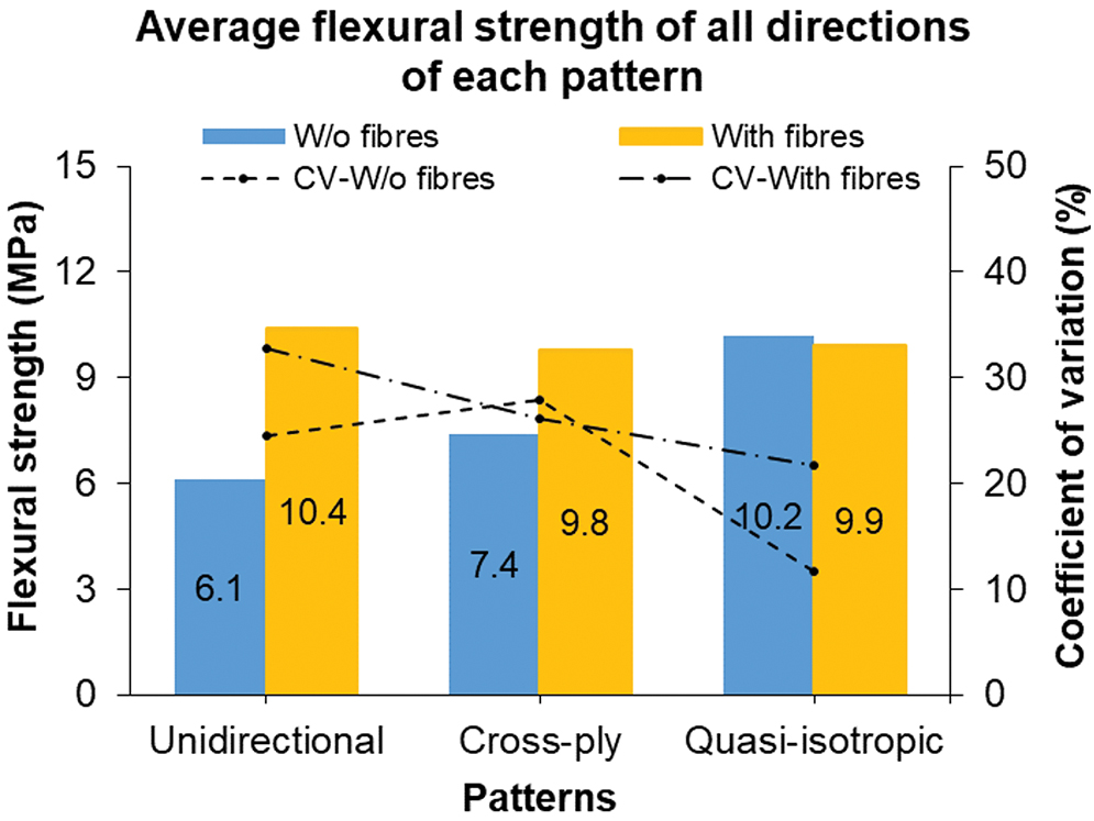
Average flexural strength of all directions of each pattern on the bar charts (left-hand side axis) and corresponding coefficient of variation on the line charts (right-hand side axis). Color images are available online.
Due to the inherent brittleness of concrete, all samples without fibers are complete failure into two parts, which are not provided herein. The same observation is found for samples with fibers in direction X. In the meantime, Figure 11 shows less catastrophic failure of samples with steel fibers, particularly two parts of a beam remain connected by fibers after being tested, in directions Z1 and Z2 (except unidirectional samples in direction Z2). For fiber-reinforced samples, cross-ply and quasi-isotropic patterns have moderately lower flexural strengths in direction Z1, slightly lower in direction Z2, and slightly higher in direction X when compared with their unidirectional counterparts (Fig. 7b). Thus, there is no significant difference in the flexural strengths of samples with fibers in each direction among patterns. However, the arrangement of steel fibers into cross-ply and quasi-isotropic layups can prevent catastrophic failure in two directions Z1 and Z2 instead of only one direction Z1, as in the unidirectional control.
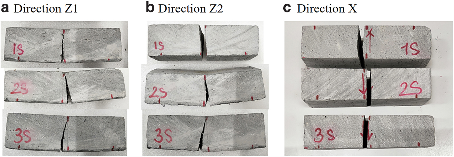
Crack patterns of the flexural test specimens with fibers in direction Z1
X-ray micro-CT results
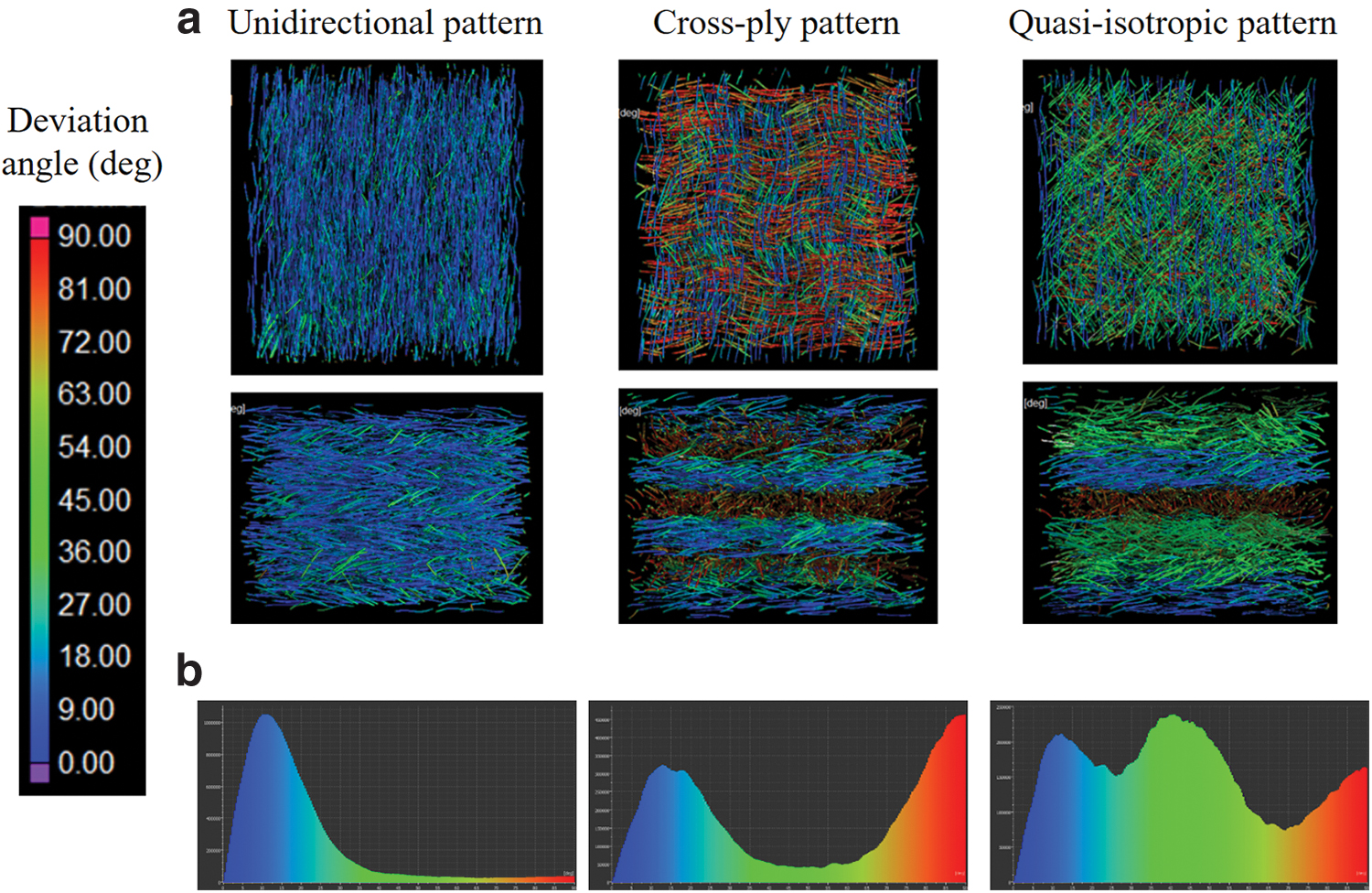
The X-ray micro-CT results are shown in Figure 12a; the orientation of fibers of each layer in each pattern is visualized with different color codes. The histogram in Figure 12b demonstrates that 95% of the total fibers in the unidirectional pattern lie between 0° and 30° around the reference orientation. Meanwhile, the fibers of cross-ply 0°/90° fall into two opposite main directions, around the parallel and perpendicular to the printing direction of the first layer. The steel fibers in a quasi-isotropic sample lie in four main directions, which are demonstrated in three clear parts in the histogram.
Effect of helicoidal patterns
Mechanical properties of helicoidal samples with three different pitch angles of 10°, 20°, and 30° are presented and compared with those of their unidirectional counterparts. The orientation of steel fibers in these patterns obtained from X-ray micro-CT tests is also displayed.
Compressive strength test
The compressive strengths of samples with and without fibers vary in a range of 86.4–110.2 and 92–120 MPa, respectively, as shown in Figure 13. For samples without fibers, helicoidal structures lead to an increase in the compressive strengths relative to the unidirectional control in each direction (except direction X, the helicoidal 3) (Fig. 13a). Helicoidal arrangements of matrix layers have the most pronounced effect on compressive strengths in direction Z, increasing by 11.8%, 26.5%, and 19.3% in samples with pitch angles of 10°, 20°, and 30°, respectively. In the meantime, the compressive strengths of helicoidal samples in directions Y and X increase by up to 13.6% and 5%, respectively. Rotating matrix layers into helicoidal arrangements by any pitch angle leads to higher resistance against compression load for samples without fibers. A similar observation is found in cross-ply and quasi-isotropic layups, which is attributed to a tight connection within the printed sample due to various directions of layers.
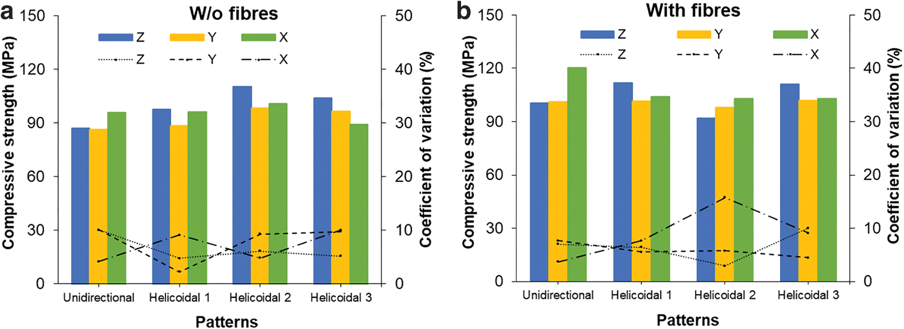
Compressive strengths of all specimens printed without fibers
The use of fibers, in general, has a positive impact on the compressive strengths compared with their counterparts without fibers, increasing up to 25.8% (Fig. 13b). The most considerable influence is for unidirectional samples, increasing by 15.4%, 17.2%, and 25.8% in directions Z, Y, and X, respectively. Of all three helicoidal angles, the presence of steel fibers makes more significant contributions to the improved compressive strengths of samples with angles of 10° and 30°, over those with an angle of 20°.
Compared with the alignment of fibers in the unidirectional pattern, multiple directions of fibers in helicoidal structures (Fig. 13b) have some positive impact on the compressive strengths, but generally remain unchanged or decreased. The CVs of the compressive strengths vary between 2.2% and 15.8%.
The average compressive strength and its CV of each pattern are shown in Figure 14. Interestingly, helicoidal structures with fibers have much lower CVs (under 5.7%) in comparison with unidirectional control (10.5%), meaning a significant decrease in the directional dependence of compressive strength tests in helicoidal samples. A single direction of fibers is acknowledged as a cause of anisotropic mechanical properties in other materials.34–36 On the contrary, CVs of the compressive strengths of helicoidal patterns without fibers (5.2%, 6.2%, and 7.7%) are generally higher than those of unidirectional counterpart (5.9%); however, the difference is not significant.
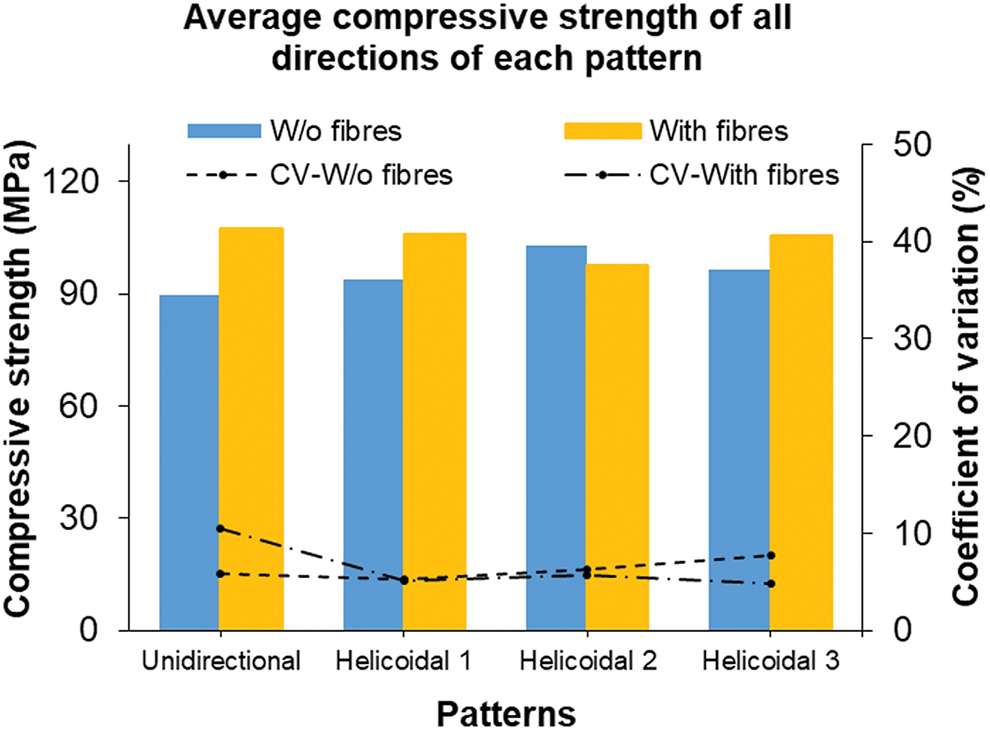
Average compressive strength of all directions of each pattern on the bar charts (left-hand side axis) and corresponding coefficient of variation on the line charts (right-hand side axis). Color images are available online.
Flexural strength test
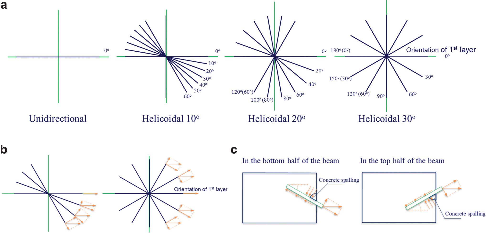
The helicoidal arrangements of layers in samples without fibers demonstrate increases by 15.4–25.6% in the flexural strengths in direction Z1 relative to the unidirectional layup, as shown in Figure 15a. The main reason for this observation can be the more robust connections within a printed sample caused by multidirectional layers generating higher mechanical responses. A more pronounced influence of helicoidal structures is found for samples tested in direction Z2, in which the flexural strength of the helicoidal samples with a rotation angle of 10° increases by 73.5%, while the value of 38.8% for those with greater rotation angles of 20° and 30°. This observation is attributed to complete changes in the interface configuration because concrete layers are periodically rotated according to helicoidal patterns. More specifically, the real interface only exists in the first layer of helicoidal samples, and from the second layers, layers across the interface, which can prevent susceptibility to splitting at the interface and thus increase bending strength. For direction X, helicoidal samples without fibers have the same or slightly decreased flexural strengths compared with the control. The observation is unsurprising because all samples tested in this direction are highly prone to splitting at the horizontal interface. Rotation of layers following helicoidal arrangements by the pitch angles of 10° and 20° is not likely to form interlocking between layers, as shown in Figure 2. If it could be, the interlocking in 30°-angle samples is shallow, which is not strong enough to create an interlocking mechanism to improve strength in direction X.
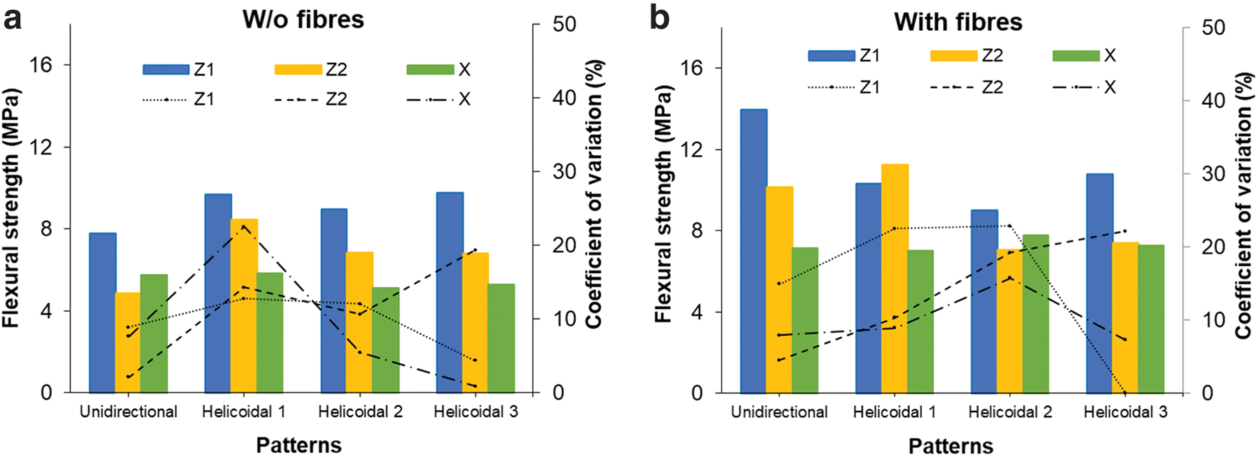
Flexural strengths of all specimens printed without fibers
The effect of steel fibers on the flexural strengths of unidirectional samples in direction Z1 is the most pronounced, increasing by 78.2% (Fig. 15). Meanwhile, an increase of up to 10.2% in this direction is found for helicoidal samples. These results are attributed to highly oriented fibers, along with the beam length, more beneficial for bending resistance over multidirectional fibers in helicoidal patterns. While the unidirectional arrangement of fibers can generate a fiber bridging effect to increase flexural strength, fibers in the helicoidal patterns are distributed in different inclination angles relative to the centerline of the beam, reducing the reinforcement efficiency of steel fibers on flexural response. This is also the reason why the flexural strengths of helicoidal samples with steel fibers, which are not significantly different from each other, are 22.3–35.3% lower than the unidirectional counterpart (Fig. 15b).
In direction Z2, a significant increase of 108.2% in the flexural strength of unidirectional samples with fibers with respect to the counterpart without fibers. The reason for this improvement is explained in the Flexural Strength Test section. For the same direction, of all helicoidal patterns, the use of fibers has the most influence for 10°-angle helicoidal samples, increasing by 32.9% compared with the samples without fibers, while values for 20°- and 30°-angle specimens are 4.4% and 8.8%. When compared with the flexural strength of unidirectional samples in direction Z2, that of 10°-angle samples increases by 10.8%, but those of 20°- and 30°-angle samples decrease by 30.4% and 27.5%, respectively (Fig. 15b).
It can be noticed that 20°- and 30°-angle samples have more fibers crossing the interface at different inclination angles but less reinforcement efficiency in flexural resistance than unidirectional samples with fibers aligned perpendicular to the length of the beam. The most likely explanation is that the larger the angle fibers rotate, the more the stress is transfered between matrix and fibers causing sudden changes in the direction of local stresses, leading to severe failure and reduced effect of fibers. Although the flexural strengths of samples tested in direction X are mainly dependent on the interfacial bond strength, the presence of fibers (even in the direction perpendicular to the longitudinal axis of the beam) somehow increases splitting resistance between layers. As a result, samples reinforced with fibers show 20.7–52.9% higher flexural strengths in direction X compared to their counterparts without fibers. Like samples without fibers, there is an insignificant difference in the flexural strengths of samples with fibers in direction X (Fig. 15b).
The 10°-angle helicoidal samples without and with fibers show higher flexural strength in direction Z2 than those of 20°- and 30°-angle samples, as presented in Figure 15. In directions Z1 and X, the strengths of helicoidal samples with angles of 10° and 30° are quite similar, while those with an angle of 20° are slightly different. It seems like the 10°-angle helicoidal arrangement of printed concrete has more benefits for flexural strengths. The advantageous characteristics of the small-angle helicoidal structure of laminated composites can be found in existing studies.37,38
Similar to unidirectional, cross-ply, and quasi-isotropic patterns, helicoidal sequences show the highest flexural strengths of both concrete without and with fibers in direction Z1 (except for 10°-angle layup). The reason for the observation is well-explained above. The arrangement of printed concrete into helicoidal structures almost eliminates the vertical interface in samples tested in direction Z2, except for the interface at the first layer. This change results in significantly higher flexural strengths of samples without fibers in direction Z2 compared with those in direction X (Fig. 15a). The lowest flexural strengths in direction X of helicoidal samples without fibers are because it is highly susceptible to splitting at the horizontal interface. Unlike cross-ply and quasi-isotropic patterns, there is no interlocking formed in helicoidal structures, as discussed above. The unidirectional and 10°-angle helicoidal samples with fibers demonstrate considerably higher flexural strengths in direction Z2 than in direction X (Fig. 15b). However, the flexural strengths of 20°- and 30°-angle helicoidal samples with fibers in direction Z2, which is significantly lower than that of 10°-angle counterpart, demonstrate the lower or the same as those in direction X. The low bending strength of 20°- and 30°-angle samples in direction Z2 is attributed to larger rotation angles of fibers possibly causing more sudden changes in the direction of local stresses, leading to twisted crack in failure patterns and reducing bending capacity.
The average flexural strength of each pattern and the corresponding (coefficient of variation [CV]) are shown in Figure 16. The average flexural strength of the unidirectional control without fibers is lower than that of the helicoidal structures, reflecting a clear improvement in the bending response of helicoidal samples. However, the opposite observation is found for samples with fibers, the unidirectional layup has the highest average strength, meaning the helicoidal arrangements of fibers are not really beneficial to bending strength over the control. Of all helicoidal structures, the 10°-angle helicoidal pattern demonstrates better performance with the average flexural strengths of both samples with and without fibers higher than those of 20°- and 30°-angle helicoidal counterparts. CV for the flexural strengths of the unidirectional pattern with fibers is noticeably higher than that of their helicoidal counterparts, reflecting higher anisotropic flexural properties of samples caused by highly oriented fibers. CVs for the flexural strength tests of unidirectional and 10°-angle layups without fibers are the same, which are lower than those of 20°- and 30°-angle patterns.
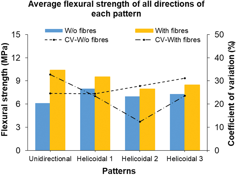
Average flexural strength of all directions of each pattern on the bar chart (left-hand side axis) and corresponding coefficient of variation on the line chart (right-hand side axis). Color images are available online.
All samples without fibers have sudden and complete failure due to the brittle nature of concrete, as presented in Figure 17. Crack plane in unidirectional samples tested in directions Z2 and X could deflect through different interfaces, and therefore, They aren't necessarily straight. 42 Crack paths of helicoidal samples with pitch angles of 10° and 20° are even straighter, and the fracture surface is flatter than those of unidirectional ones tested in directions Z2 and X (Fig. 17). However, twisted crack paths are found for 30°-pitch angle helicoidal samples without fibers, which is governed by the direction of matrix layers, reflecting a marked change in the microstructure of hardened concrete caused by the printing pattern. From this observation, the crack path of large angle helicoidal samples is twisted and complex in directions Z2 and X, leading to an increase in the crack's surface area.
Crack patterns of the flexural test specimens without fibers. Color images are available online.
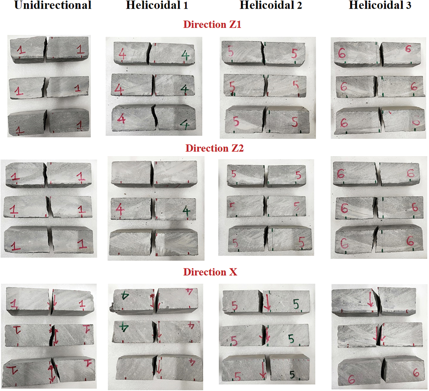
Figure 18a displays the direction of fibers periodically stacked by a constant helical angle from the first layer to the last one in the beam, and Figure 19 shows the fiber-reinforced samples after the flexural tests. All samples tested in directions Z1 and Z2 (except for unidirectional samples in direction Z2) demonstrate less violent failure in all patterns than the rest of the samples, attributed to fibers aligned at different inclination angles from the orientation of the first layer. The result demonstrates the definite benefits of using steel fibers in the prevention of failure in specific cases. Crack paths of samples tested in direction X are the similar among all patterns. The 10°-angle samples have less complex crack paths and higher flexural strength than 20°-angle samples in direction Z1, which have twisted crack patterns; meanwhile, 30°-angle samples in this direction have a quite straight crack propagation and the highest strength of all helicoidal samples, as presented in Figure 19.

Crack patterns of the flexural test specimens with fibers. Color images are available online.
In direction Z2, twisted crack patterns are found in helicoidal samples with 20°- and 30°-rotation angles with a twisted shape more obvious in the larger angle one, as exhibited in Figure 19. A twisted crack path is formed following helicoidal paths of fibers.35,55,56 Like the observation in direction Z1, 20°- and 30°-angle samples in direction Z2, which show twisted crack propagation causing expanding damage area, have lower flexural strengths over that of 10°-angle samples. During the experimental process, concrete spalling observed occurs in helicoidal samples with fibers in directions Z1 and Z2 with concrete crumbs, which does not appear for unidirectional samples, in which samples with
X-ray micro-CT results
The procedure of reconstructing the set of 2D projections into 3D volumetric data, analyzed for fiber orientations, is described in the X-ray Micro-CT Results section. Figures 20a and 18a demonstrate the orientation of fibers and the rotation angles of layers in each pattern, respectively. It should be noted the only part height of 50-mm cubes is scanned and analyzed, showing the first seven layers of the samples. Here, the reference orientation is the direction of the first layer, and so, the deviation angle of steel fibers in the first layers from the reference orientation is theoretically around 0°.
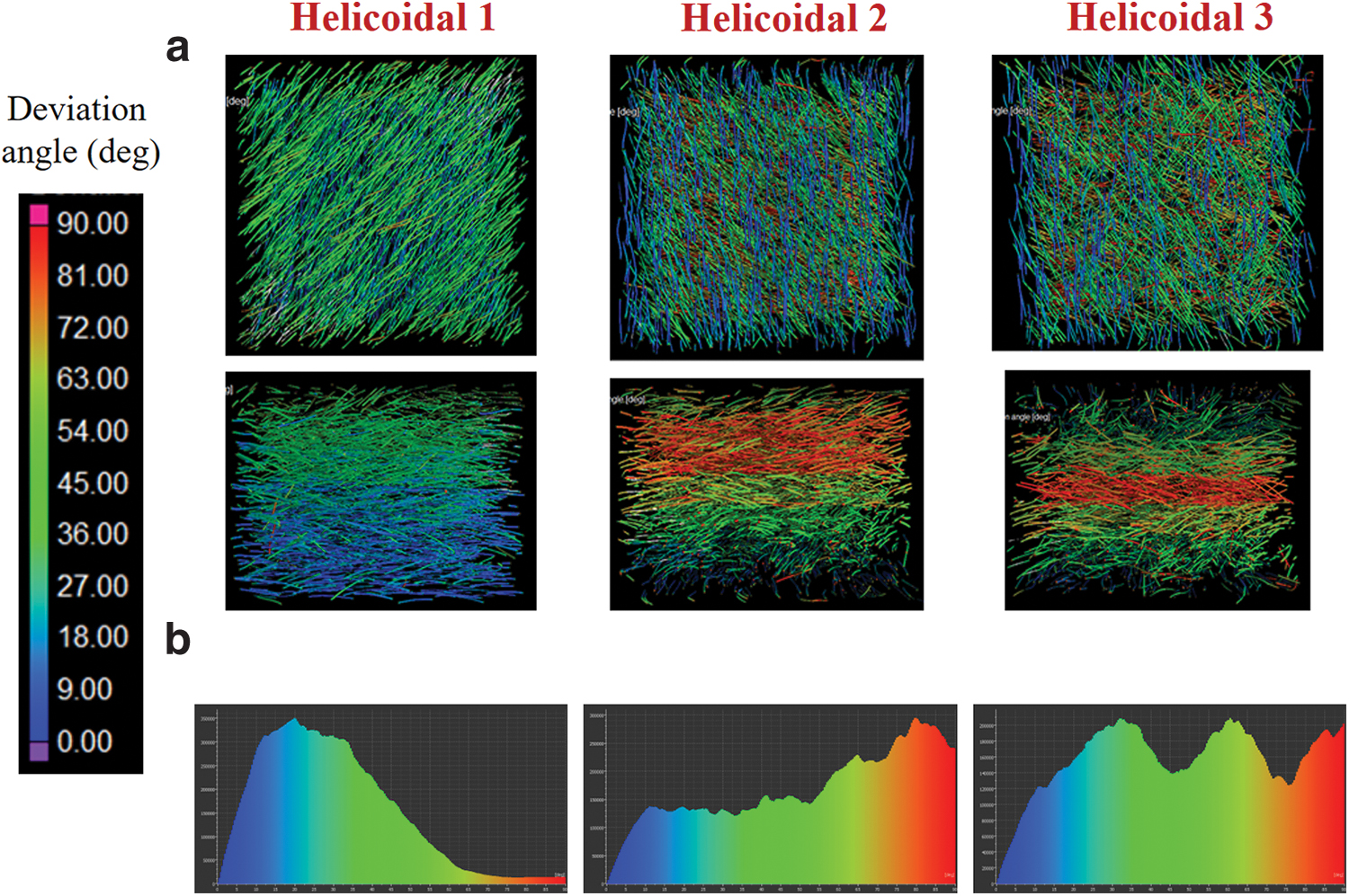
In practice, the unidirectional samples have almost fibers lying within 0°-30° from the reference orientation, as shown in the histogram in Figure 12b. Meanwhile, the 10°-angle helicoidal samples have stacking sequence of 0°/10°/20°/30°/40°/50°/60°, fibers falling between 0° and 60°, as can be seen in Figures 18a and 20b. The 20°-angle helicoidal samples have stacking sequence of 0°/20°/40°/60°/80°/100°/120°, fibers falling between 0° and 90°, and there are a higher number of fibers lying between 60° and 90° (Fig. 20b), which is also displayed in Figure 18a with four layers surrounding the direction perpendicular to the direction of the first layer. The 30°-angle helicoidal samples have stacking sequence of 0°/30°/60°/90°/120°/150°/180°, highly intensive number of fibers at 30°, 60°, and 90° from the reference orientation.
Conclusions
The study focuses on investigating the effect of cross-ply (0°/90°), quasi-isotropic (0°/ ± 45°/90°), and helicoidal layups on the flexural strengths of printable concrete, with and without steel fibers, over the unidirectional control (0°). The results of the compressive strengths are also provided. Some conclusions are drawn based on the experimental results, as follows.
Regarding compressive strengths:
For the same material mix, by changing the printing patterns from the unidirectional to cross-ply, quasi-isotropic, and helicoidal patterns, it is observed an increase of up to 26.5% in the compressive strengths of samples without fibers. Here, the effectiveness of bioinspired printing architectures is generally most pronounced for the samples tested in direction Z (vertical to printing direction), which could be attributed to a stronger connection between layers in this direction. The moderate effect is found on the compressive strengths of samples in direction Y; meanwhile, there is an insignificant influence of the printing patterns on those in direction X. Interestingly, these effects are consistent from pattern to pattern. When compared with samples without fibers, those with steel fibers have higher compressive strengths in any direction of any architectural pattern with a few exceptions. When compared with the fiber-reinforced unidirectional samples, the unconventional counterparts have higher compressive strengths in direction Z (except for 20°-angle samples), almost the same in direction Y, and lower in direction X. Similar to samples without fibers, the effect of different patterns is more pronounced on the compressive strengths of fiber-reinforced samples in direction Z.
Regarding flexural strengths:
All bioinspired patterns improve the flexural strengths of samples without fibers in directions Z1 and Z2 over the unidirectional control, in which significant enhancement is observed for quasi-isotropic samples. The effect of cross-ply and 10°-angle layups is also noticeable in these directions. Besides, cross-ply and quasi-isotropic patterns had positive influences for the flexural strength of samples tested in direction X, in which the effect of quasi-isotropic structure is more pronounced. In the meantime, the rotation of matrix layers into helicoidal patterns by the pitch angles of 10°, 20°, and 30° does not create interlocking mechanism, thus leading to limited improvement in the interfacial strength in the horizontal direction. It can be concluded that for samples without fibers, the quasi-isotropic can be considered an optimal print pattern in both the horizontal and vertical directions. Of all helicoidal architectures, the 10°-angle helicoidal pattern is the most beneficial to the flexural strengths of samples without fibers over the unidirectional control.
The addition of steel fibers generally increases the flexural strengths in any patterns in comparison with counterparts without fibers. The most pronounced enhancement is found for the unidirectional samples, and the moderate effect is observed for cross-ply and helicoidal samples. However, the insignificant effect of steel fibers is found for quasi-isotropic specimens in all directions. Quasi-isotropic layup is an optimal arrangement for samples without fibers, and the addition of steel fibers in this pattern does not promote its effect.
In comparison with the unidirectional fiber-reinforced samples, there are decreases in the flexural strengths in the unconventional counterparts in both directions Z1 and Z2 (except for 10°-angle helicoidal samples in direction Z1). Significantly decreasing flexural strengths in these directions are found for 20°- and 30°-angle helicoidal samples, which also show crumb concrete dropping during the test. Meanwhile, a slight increase in the flexural strengths of the unconventional samples with fibers in direction X over that of the unidirectional counterpart. Although the unconventional patterns lead to no noticeable effect on the flexural strengths of fiber-reinforced samples over the control, they can prevent catastrophic failure in both directions Z1 and Z2 instead of only direction Z1 in the unidirectional samples. Of all unconventional patterns, the quasi-isotropic, cross-ply, and 10°-angle helicoidal layups are more beneficial in bending performance over 20°- and 30°-angle helicoidal arrangements.
The unconventional counterparts have lower CVs for both compressive and flexural strengths between directions. This reflects the alleviation of directional dependence of mechanical properties in the unconventional layups (cross-ply, quasi-isotropic, and helicoidal patterns) over the unidirectional control. The CVs of the flexural strengths of all directions in each pattern (11.9–32.8%) are significantly higher than those for compressive strengths (5.2–10.5%), reflecting the higher degree of anisotropy of the flexural strength tests between loading directions.
There are definite enhancements on the mechanical properties of printed concrete resulting from the unconventional printing patterns, which have a promising potential for being applied in highly complex or self-supporting concrete architectures.
Footnotes
Acknowledgments
The support of the technical officers (Civil Engineering), Department of Civil & Infrastructure Engineering, School of Engineering, RMIT University, is gratefully acknowledged. We also highly appreciate the assistance of undergraduate students in experimental work.
Author Disclosure Statement
No competing financial interests exist.
Funding Information
This work is supported by the VIED-RMIT Scholarship.