
Abstract
3D extrusion of spatial wireframe provides an alternate method for additive manufacture, which holds a significant advantage over the typical layering printing method in terms of material and time efficiency. However, the complexity of the structure and unsupported printing process are major challenges for path planning of extrusion process. This article presents a method to plan and control the path for extruding 3D spatial wireframes by synthesizing dynamic material behaviors such as heat deformation, plasticity, and bending, during the curing process as active contributors to the printed form. With this method, a novel system of printing spatial wireframe model is developed that disassociate the extruding path and extruded form by dimensional, that is, printing a 3D spatial wireframe with a 2D printing path. The workflow of the research combines robotic/mechanical automation with machine vision and artificial intelligence, to generate material models without any preexisting knowledge of the material. Based on the feedback loop between machine vision and printing control, this system is capable of automatically conducting material experiments at a large scale, observe the results, and learn to generate an end-to-end solution that directly bridges the design intention to the fabrication of spatial wireframes based on nonstandard material behaviors. The development of the method allows designers to design and fabricate dynamic spatial frames, without the support of existing material and structural models.

Introduction
Additive manufacturing (AM), which is also known as 3D printing, enables the fabrication of complex geometries. Among the categories of 3D printing, low-cost plastic-based 3D printing systems that use material extrusion are becoming the widest spread and have captured the imagination of the general public through movements such as do-it-yourself and the maker movement. 1 Currently, fused deposited modeling (FDM) is the foundation of most AM processes. It starts with a customized 3D solid object, which is sliced into thin layers. 2 Each layer is printed with the planned sequential deposition of materials from the bottom up. Current layer-based AM and tools are effective at printing solid geometries, but printing spatial lattice models remains a challenge. 3
In large-scale AM, especially for architecture, nonlayered printing with spatial wireframes has a unique advantage in term of fabrication speed due to minimal mass transfer.
4
It has a strong potential for its coherence with the geometric logic of network surfaces or mesh frames and the structural logic of stress lines used during optimization process. AM based on spatial wireframe extrusion can be used to build larger structures with faster and less deposition of printing materials, which makes it especially adaptable for fabricating large-scale formwork.
5
Although the potential of AM with nonlayered spatial wireframe extrusion is apparent, a few key issues constrain its application:
Special fabrication hardware is required for additional flexibility of the extruder Compared with layered 3D printing, where the movement of the effector is clear from the printed space, spatial wireframe extrusion is often confronted with the possible collision between the movement of mechanical parts and the printed object during the printing process. Thus, instead of the typical 3D printing mechanism with only three degrees of freedom, more flexible and agile robots with six degrees of freedom are necessary for the spatial extrusion of wireframe models. This makes it difficult to adapt current 3D printing systems to commercially viable solutions. Progressive deformation of parts during the printing process n contrast to the layered printing process, where each layer is fully supported during printing, spatial wireframe extrusion prints struts sequentially. Although the overall wireframe may be optimized as a stable structure, the parts are less stable during printing. The deposition process involves phase changes of the material, which is also a major cause for the deformation of parts during an unsupported printing process.
6
Such deformation would quickly accumulate to require further calibration of the printing path. Considering all the above factors, developing a sequence plan for the parts is a crucial challenge to minimize progressive deformation during printing.
7
Computational expensive typological optimization, sequence finding, and path planning Owing to the complexity of the process, typical path planning for spatial extrusion considers not only the path itself but also a complex interplay of parameters such as the orientation of the extruder, current structure stability, material deformation at each moment, and ensuring that the previous printed part will not obstruct later components nor deform with later printing. This interdependent nature of the wireframe during printing exponentially increases the solution space for optimization, sequence finding, and path planning.
6
For example, path planning for a simple geometry such as the Stanford Bunny would take 10–20 h on a personal computer to complete.
Thus, we concluded that, compared with the typical layered printing, the complexity and challenges for spatial wireframe extrusion mainly result from the following factors:
The intertwining of the mechanical fabrication space and built space due to the overlay of target geometry to be printed and the printing path, which mainly accounts for the need of six-axis motion planning for the extruder and extruding sequence planning for the struts to avoid collision.
The interplay of compound forces and dynamic material properties during the curing process lacking an established simulation method, which is the main cause for the accumulated deformation at each step of the extrusion process and the extremely high computational expenses.
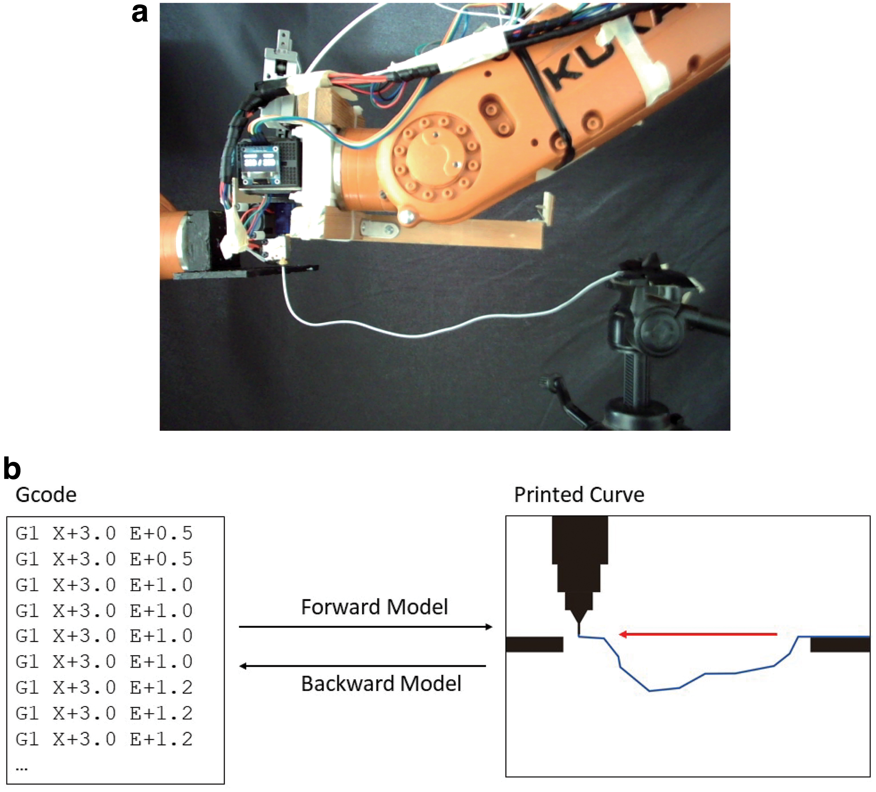
Based on recent developments in robotic automation, machine vision, and artificial intelligent, we present a systematic computational approach to understanding the relationships between the material, form-finding, and fabrication. This novel workflow is capable of finding the relationships between a wide range of materials and fabrication methods without an explicit understanding of the material properties and mechanism. In contrast to commonly adopted digital design tools and fabrication methods such as additive fabrication, subtractive fabrication, and lost-foam casting, this comprehensive workflow actively utilizes factors such as material deformation, bending, and melting to shape the printed output instead of considering them negative factors that need to be mitigated. Automated robotic testing, image processing, and deep learning are utilized in the process. This research enables a common fuse filament 3D printing to extrude 3D spatial curvature and wireframe by utilizing the heat deformation of material, the application of neural networks (NN), as well as an automatic robotic testing workflow (Fig. 1a). The novel spatial extrusion method developed in the research addresses the above challenges as follows:
Disassociation between the printing path and target geometry, which means that the mechanical fabrication space and built space are no longer intertwined. In our system, the 3D spatial wireframe can be printed with the end-effector moving along a 2D plan, which makes it adaptable to commercial polylactic acid (PLA) printers and reduces the need and cost for six-axis fabrication equipment.
Training an end-to-end NN model that directly maps the fabrication control parameters to the printed outcome (Fig. 1b), without the need to understand the interplay between forces and material behavior during the extrusion process. The model instantly generates a path planning and control code for the target spatial wireframe without the need for optimization by iterative simulation and calculation of the forces and deformation.
Background
Although there has been extensive research on layered 3D printing methods, nonlayered AM processes and tool path planning may further expand the capabilities of AM technology in the future. 1 Compared with layered AM, which operates on a solid mass and planar boundaries, 3 this research investigates into the printing of spatial wire frame or single-layer lattice structures based on the composition of linear extrusion itself. The shift in target geometry from solids to spatial lattice has led to new challenges. 3 In layered printing methods, the extruded materials are sufficiently supported by the material beneath; however, typical supporting method will not work for spatial extrusion. Thus, typical lattice structure is printed with techniques where the prints are supported via removable materials such as liquid,8,9 powders, 10 or stereolithography (SLA). 11 This method is constrained by the size of the container and relatively expensive equipment compared to the fuse filament printer.
Owning to the wide availability of fuse filament printer, another research direction investigated into utilizing typical filament printer to print spatial lattice. One solution requires a combination of fabrication techniques, where formwork is made first to support spatial curvatures before the target geometries are printed on top.12,13 These methods require additional fabrication of the supports and are only applicable to printing a surface with a single layer. Alternatively, FDM technology with double extruder that couple acrylonitrile butadiene styrene (ABS)/PLA and hydrosoluble material such as polyvinyl alcohol (PVA) is also capable of building lattice structure with polymers for bioengineering.14,15
However, unsupported spatial wireframe printing with fuse filament printer is far more complicated as it required the progressive optimization of self-supporting wireframe structure,16,17 as well as the fabrication path planning where the operation space of the extruder is constrained by both the spatial geometry and sequence of operation. 7
The 3D spatial extruded wireframe has showcased significant application in architecture such as rapidly printing of 3D spatial mesh frame for casting, 2 structure surface printing with principle stress line, 18 and base frame printing for objects and furniture. 19 In research on mesh molds 5 and iridescence printing, 20 spatial extrusion was used to fabricate a truss in a layered manner. Yu and Luo 6 and Huang et al. 21 investigated the path planning of spatial extrusion by following the topology of the wireframe model itself instead of reinterpreting it as a solid model with infilling of truss frames. Owing to the overlay of the extrusion path and target geometry and the interplay of complex forces during the extrusion process that lack a sufficient simulation method, several challenges remain before commercial application of this process, including the progressive deformation of parts during the printing process; computational expensive topological optimization, sequence finding, and path planning; and specialized fabrication hardware to realize additional flexibility for the extruder. In the case of Gantry Autonomous Robotic Integration (GARI) system, the robotic additive process is achieved with assemble of prefabricated components. 22 Although such system drastically increased the assemble speed, the prefab components significantly restrict the flexibility of the assembled structure. The objective and contribution of our study were disassociating the printing path and target geometry to reduce the constraints on the path planning and building a method that can directly map the fabrication control to the final cured spatial wires considering the impact of diverse forces.
Currently, with the emergence of machine learning (ML) and NN, various studies have been conducted to investigate how ML could be applied in 3D printing. Based on a recent review, 23 current applications fall into the following categories: (1) increase printability of design; (2) part quality/process optimization; (3) in situ monitoring for quality control; and (4) Cloud printing and service platform. However, from using knowledge-based artificial neural network (ANN) to make part estimation, 24 using ANN to predict build time 25 and shrinkage ratio, 26 to using convolutional neural network (CNN) for tracking continuity, 25 most of the current application focus on optimizing existing 3D printing process with ML algorithms. 27 How the development in NN could potentially impact the systems of 3D printing, to offer novel 3D printing method with the expanded ability of NN to understand the nonlinear correlation between data sets such as mechanical control and printed form, is yet under investigation.
Experimental Description: 3D Printing with Dynamic Heat Deflection
Institutional review board (IRB) statement: this article does not contain any studies with human or animal subjects performed by any of the authors, thus waived from the IRB approval.
This research focused on transforming one of the most common fabrication technologies: 3D printing with PLA. We developed a system for the printer to print a line across two supports at both ends and let the material naturally drip into a curve. The workflow was used to generate an NN model that could recognize the relationship between the fabrication control code and dynamic outcome of the spatial curvature after heat deformation when 3D printed in an unsupported manner.
The changes in the extrusion and movement speeds were determined with Gcode. As a thermoplastic material, the PLA string will solidify into a curve with uneven curvature when printed in such unsupported manner due to the complex interactions of gravity and intermolecular forces. This printing system differs from the current additive layering printing system and offers the novel possibility of printing 2.5D or 3D spatial wireframes efficiently without additional support. Owing to the complexity of intermolecular forces, unknown material properties, and so on, such spatial wireframes cannot be designed and programmed with traditional path planning and material approaches. We applied the same workflow combining mechanical automation, computer vision, and artificial intelligence (AI) to develop two NN models: a forward model to calculate the printed curve via the given Gcode and a backward model to predict the Gcode controlling the printer by giving the curve that the designer intended to print.
In contrast to common applications of general purpose AI to image processing and speech recognition, where there are abundant data sets for training, data collection for the specific purpose of our research was a crucial challenge and is a common key constraint for many AI applications. In this study, much of the innovative effort was dedicated to creating an automated workflow that could conduct the experiment and collect formatted data sets in large quantities with minimum effort. Such a goal was achieved by setting up the hardware for the automated experiment pipeline and a software image processing system to output the experimental results into formatted data sets.
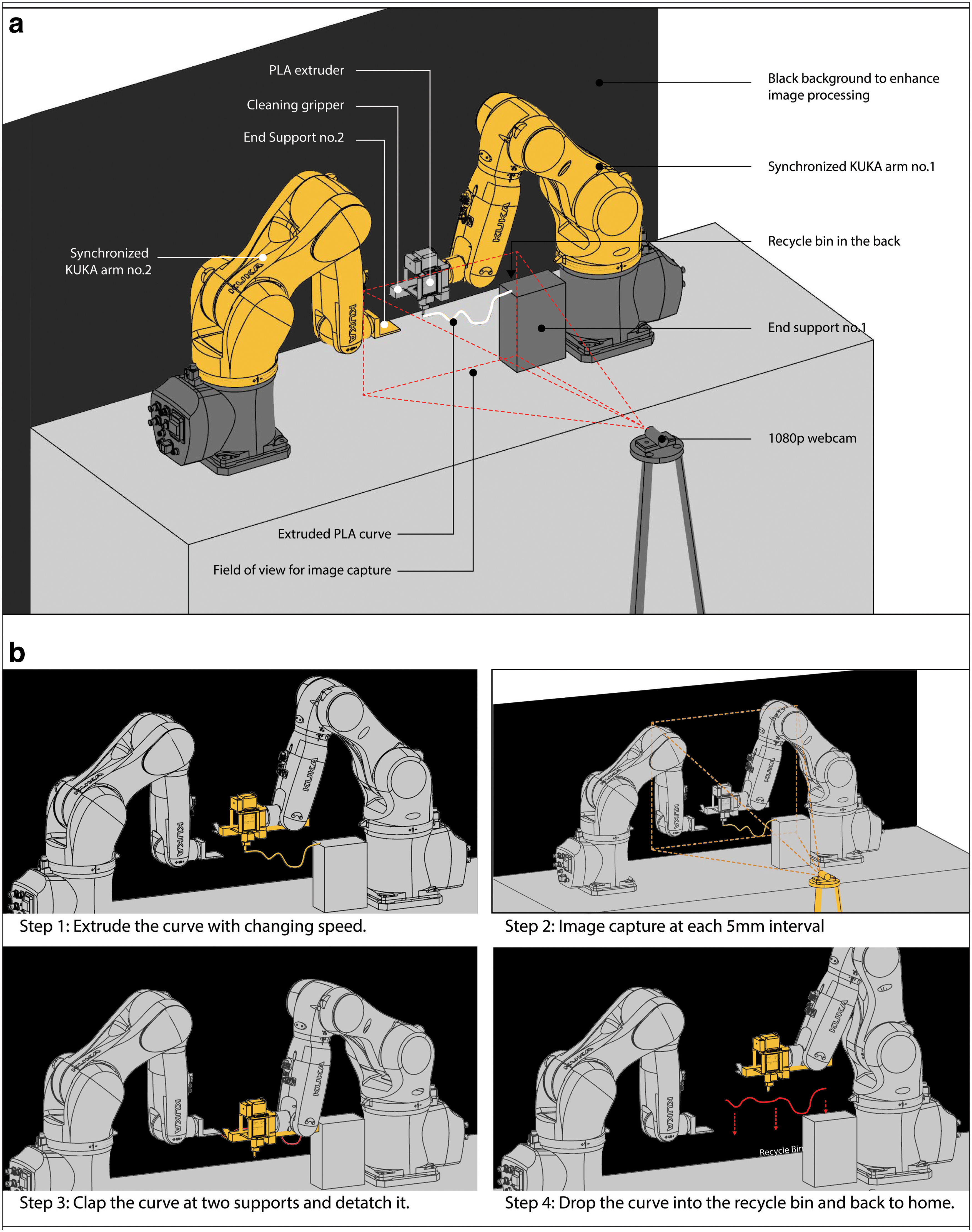
Hardware setup for the automated experimental pipeline
Few different iterations of experimental prototyping hardware platforms are developed in this research. The most effective hardware setup utilized two synchronized KUKA robotic arms. One robotic arm was responsible for supporting one end of the extrusion. It was designed so that the distance and difference in elevation between the two supporting ends could be customized and controlled with input parameters, which would in turn be an input feature for the NN to consider. The other robotic arm served multiple purposes. The end-effector of the second robot arm comprised two parts: a PLA near-end extruder with a Volcano hot-end and a 1.5 mm bronze nozzle with a 3 mm PLA roll as the printing material. This ensured a smooth extrusion process that was responsive to changes in the extrusion speed. The other side of the end-effector included two pneumatic grippers spaced apart. After extrusion and documentation, the fifth axis of the KUKA robot rotated and used the gripper to remove the printed result and clear the experiment space (Fig. 2a). Afterward, the end-effector rotated back and moved the extruder back to its home position. This complete the full cycle and got the hardware ready for the next round of the experiment (Fig. 2b).
Obtaining training data sets
Two sets of data are obtained via the automated pipeline: Data set
Data set C for controlling parameters
The extrusion process was characterized by two parameters for every
To maximize the effect of each printing and train the NN to adapt to diverse lengths, the experiment was optimized so that all curves were printed with a uniform horizontal length of 300 mm rather than at different distances between the supports. Images of the printed results are captured with a 1080p video camera triggered every 10 mm of movement by the robot. Thus, if the minimum length was 50 mm, each printed curve outputted 26 training samples, by taking picture at every 10 mm horizontal interval (Fig. 3a) between 50 and 300 mm. In this way, 500 printed curves could be expanded to a data set of 13,000 samples, and 2000 printed curves would generate a data set of 52,000 samples. This significantly increased the scope and accuracy of the validation of the NN model. To ensure the best quality of image capture so that the profile of the printed curvature could be clearly read, the system printed a white PLA curve against a black background for maximum contrast.
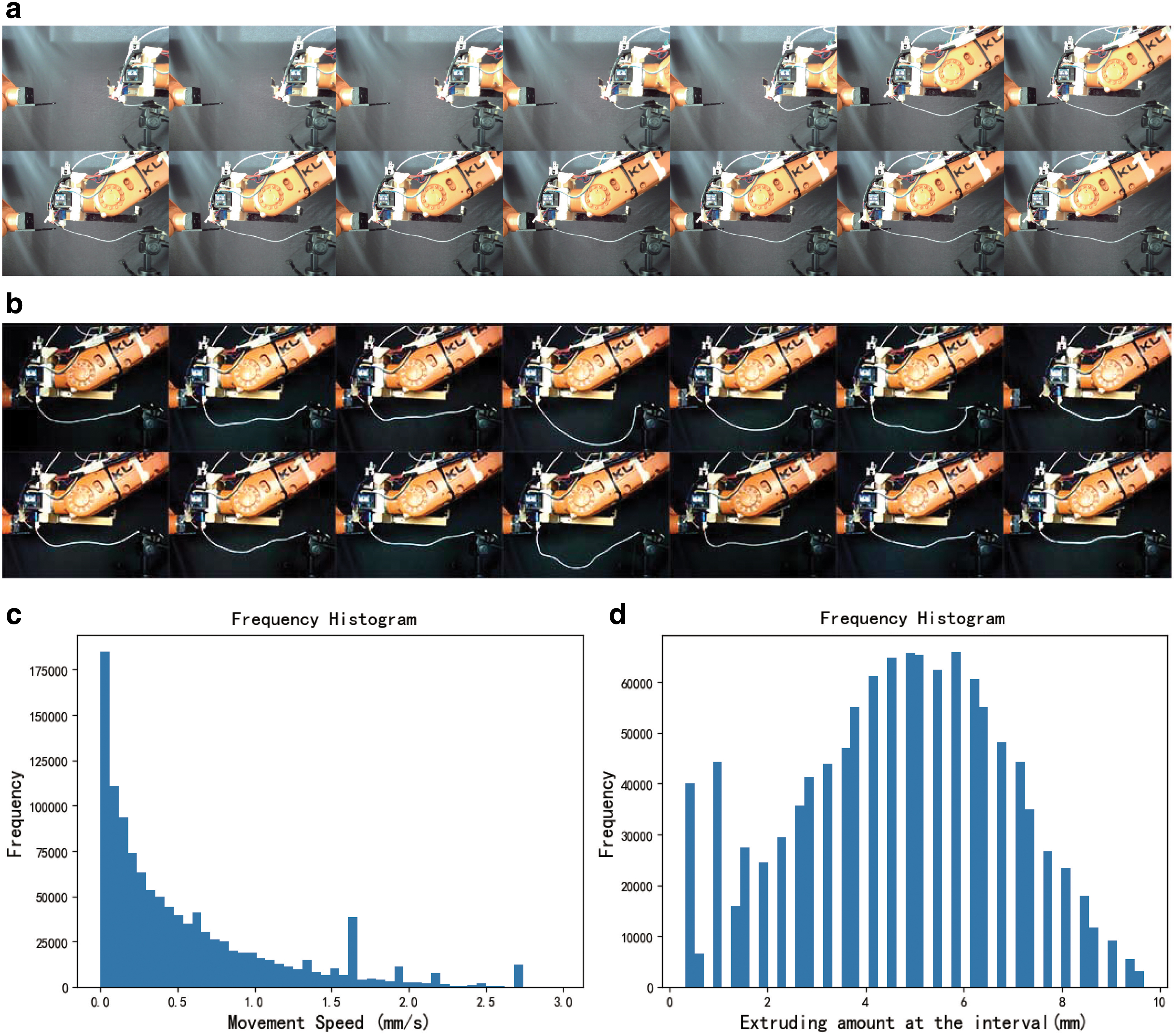
With this pipeline, the printing cycle of each curve took ∼3 min, and 26 samples could be extracted from the printing process of each curve. Ideally, such a system could be running 24-7 with minimum human interference, which would mean printing 480 cycles and collecting 12,480 samples of different lengths per day. In reality, owing to safety regulations, we managed to run ∼2000 cycles in 2 weeks (Fig. 3b) and cleaned into 35,357 valid samples. Figure 3c shows the distribution of the parameters for movement speed in the valid samples, and Figure 3d shows the distribution of the parameters for extruding speed. This innovative hardware setup for automatic testing and data collection was core to collecting a sufficient data set to make the supervised learning process possible.
The values of e and s are generated randomly based on a set of predecessor manual test that defines the approximate valid range. The range of raw value of extruding speed e is (0.0, 31.0), and the range of raw value of movement speed s is (0.0, 10.991138). However, as the robot is run at 30% of full speed, such values can be converted to E and X values in Gcode for 3D printer by multiply 30%. Figure 3c and d shows the distribution of the converted values in the data set.
Data set D for extruded curvature
As there are no existing algorithms to reverse calculate the machine code from predetermined target curvature, all curvatures collected in the data sets are the natural printed outcomes of the randomly generated control code in data set

Fixed area cropping (Fig. 4a): reduces the size of image to a predetermined boundary that removes unnecessary background information.
Binarization: binarization of the image with an adjustable threshold function in OpenCV.
Image denoising: areas of continuous white pixels are measured, and only the largest area of white pixels is maintained as the main body of curvature, whereas smaller areas are considered noise and removed.
Adaptive crop: crop down the image furthermore to the bounding box of the main body of extruded curve.
Feature extraction: based on the calibration and measurement of reference points, the conversion between the pixel distance and the physical dimension is 1 pixel = 1 mm. As the pixel distance is maintained during the image processing, key training features can be extracted from the processed images. The cropped images are sampled from right to left every 5 pixel column. The
Zero padding (Fig. 4b): since the number of features extracted is different for each segment, all input data sets
Data validation: the information of D is further reflected and superimposed onto the original image so that our system could quickly flash through it to validate the extracted information and remove any failures. Image processing failures are mainly due to interim errors in the mechanical system, such as breaking of the printed curve or failure to remove previous curves that interfered with later results. Thus, the data set is needed to be validated before being used for training.
Training of NN and evaluation
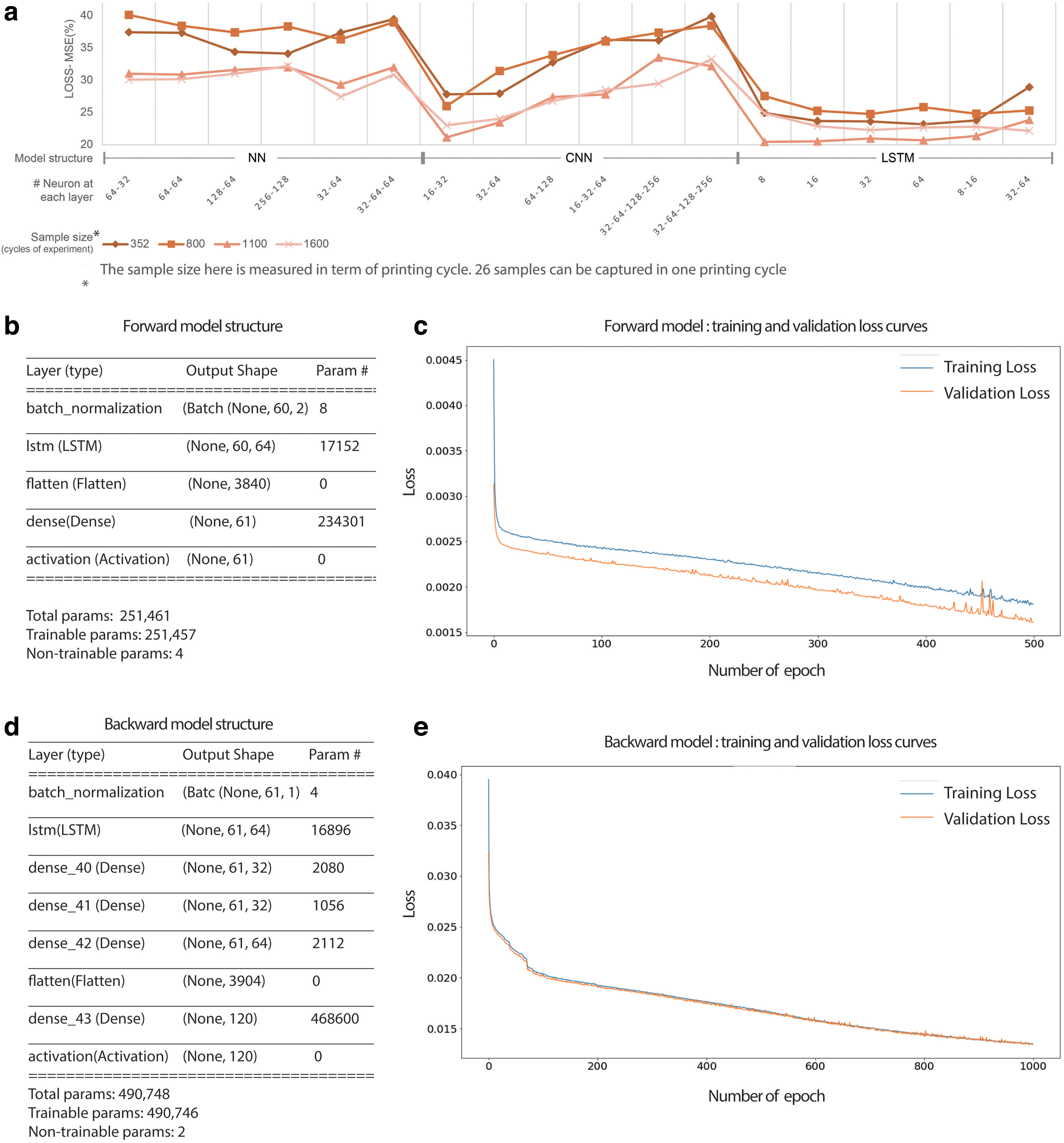
A major constraint on wider NN application is its hunger for training data. An NN requires an adequate amount of training samples. In contrast to image and natural language samples, which can easily be collected from the internet and databases, training samples for fabrication and material models are collected at a significantly higher cost, both financially and time-wise. Our research showed that the losses of the models significantly decreased as the number of printed samples was increased from 500 to 2000 printed curves (Fig. 5a). With 500 samples, we were able to systematically reduce losses by tuning the NN and increasing the training epoch. With 1200 samples, we were able to train an NN that outputted Gcode to print curvatures that followed the general trend of the target curve in an unstable manner. With 2000 samples, the NN model could predict the Gcode for printing curvature within its distribution in a more stable manner, where the overall flow of the surface could be clearly recognized.
Owing to the limited time, the experimental pipeline and cleaning of the data generated a data set of 35,357 valid samples. With those training samples, we were able to achieve an average deviation of 4 mm. As shown by the selected testing samples, the NN demonstrated clear potential at recognizing the mapping relationship between the fabricated curvature described by the distance of points along the curve
In addition to the impact of data size, we investigated tuning and selecting the NN for the best results. One percent of samples are kept as the test set to evaluate the accuracy of the final model, and the training validation split is 8:2 for the rest of samples.
Selecting and fine-tuning an adequate NN would significantly increase the stability and accuracy of the model. As shown in Figure 5a, the performance of common type of NN, 28 such as ANN and CNN, long short-term memory (LSTM) are compared together, with different number of units and layers for predicting the forward model. Due to the sequential nature of the data, 1D convolutional layer with kernel size 3 is used in the CNN, followed by a max polling layer with a pool size of 2. A few variances of this basic structure are studied as comparison to explore the potential of CNN, as shown in Figure 5a. Generally speaking, CNN is an improvement over ANN in this research especially with relatively simple architecture. The hypothesis is that the printing outcome at each feature point is physically related to not only the printing parameter at this point but also significantly impacted by the parameters at the adjacent feature points. This physic relationship of material behaviors during the printing process is more effectively picked up by the CNN architecture where the convolutional kernels are effectively picking up local connections with smaller number parameter. However, by far, the best performing NN for samples from the current data set was based on the LSTM model, which will be explained in detail in the following sections of this article. The result of this comparison also echoes with precedence research on deep learning-based tensile strength prediction in fused deposition modeling. 29 We hypothesize that the clear superiority of the sequence model owes to the fact that each feature point on the printed curve (i.e., distance deviation from the extruder path) is heavily affected by the series of parameters of feature points leading up to it, thus behaving similarly to the logic of recurrent NN model such as LSTM, where there exist and direct graph along the temporal sequence 30 of printing process. Based on this preliminary finding, the structure of NN is developed and refined to achieve the best performance for both forward and backward models.
The forward model
The forward model was trained to predict the shape of the extruded curve
Loss Metrics and Values for the Forward Model
The current training process is terminated after 500 epochs as the absolute error falls within the tolerance. However, the loss curved does during the training indicate there are further potential to reduce the loss. One possible solution is to use early stoppings 32 with higher number of epochs and a patience value to obtain best outcome. Early stopping is a regulation method to avoid overfitting during the training process. With a set patience value, the training process will only stop if the accuracy of the validation set does not increase after the set number of epochs, thus effectively allowing the training of higher number of epochs.
The backward model
During the training the backward model, data set
The overall loss and metric values for the training, validation, and testing set are shown in Table 2. The mean square error of the overall loss for the test set with the best backward model was 0.0131. The mean absolute error for the test set was 0.0641. This means that the predicted control parameters of the fabrication process, which included the movement and extrusion speeds of the extruder, deviated from the control parameters used to print these curves by 6.41% on average.
Loss Metrics and Values for the Backward Model
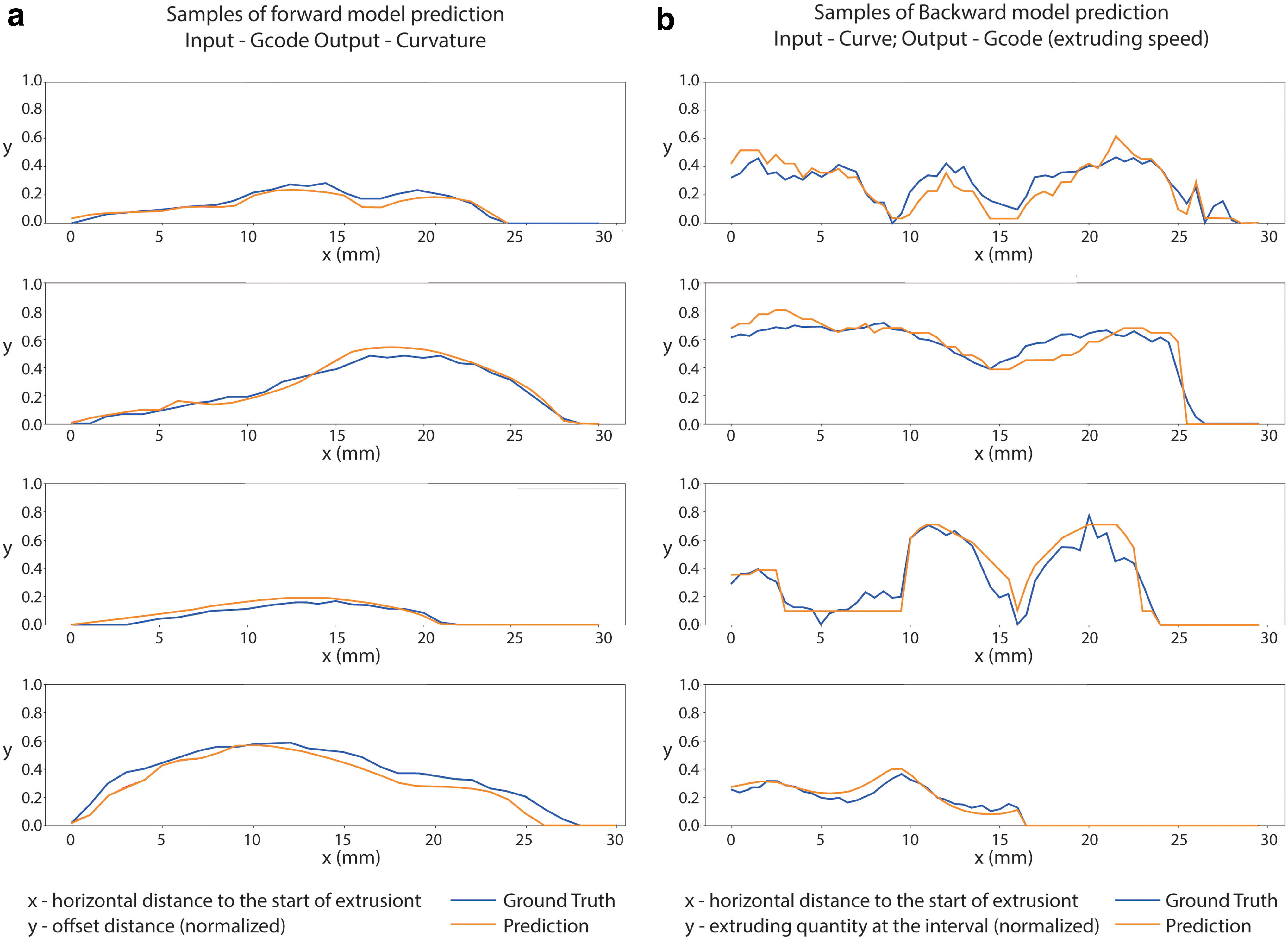
To further validate the performance of the forward NN model, the curve printed with the predicted parameters was compared with the original target curve that was input into the NN. The results showed clear positive correlations (Fig. 6a). Furthermore, to validate the backward model, the machine control variables generated from the given target curve were compared against the actual Gcode that drive the printing process. A few selected samples are shown in Figure 6b. Similar to the forward model, the accuracy of the backward model could also be improved potentially with calibrated early stopping.
Discussion
An interesting phenomenon observed during the experiment was that some of the curvatures could be printed with significantly more accuracy and stability than similar curvatures. Because the NN generates a nonlinear model, certain minor features of the target curvature can have a huge impact on the prediction. For example, one such feature that appeared during the experiment was that having a small fillet curve at both support ends increased the accuracy and stability of the printed outcome. Thus, future research should focus on quantitatively defining the scope of curvature that can be achieved with this printing method and how to optimize a random curvature for printing. A post-analysis using the NN to print diverse target curvatures can be used to collect a few common disruptive features (Fig. 7a). With this knowledge, designers can optimize the geometry for better prediction and printing results (Fig. 7b). However, this process is currently based on synthesis and observation. Further research should focus on systematically analyzing the scope of the NN and identifying disruptive features to inform the design process.

This novel 3D printing method is the result of a second study on our developed digital version of the hand–eye–mind workflow. The first study focused on building an NN model for nonuniform synthetic rubber with a similar experimental workflow. The present study on 3D printing advanced the systematic workflow as follows:
Proving that the same system can be used to build models for diverse unrelated material behaviors ranging from active bending to heat deforming.
Training an NN model by directly mapping mechanical control parameters of the fabrication machine to the output of dynamic printing, which has no existing simulation method.
Transforming the common fabrication technology of 3D printing and proving the potential of our workflow for future commercial application.
For further refinement and to improve the accuracy and stability of the system for actual application, a few key issues require further research. First, we are currently using a supervised learning method that collects a large amount of data and then feeds everything to training. In practice, we have found that, instead of training an NN that generates mediocre predictions, in many scenarios, we need the system to be optimized for prediction based on a certain type of curvature. Instead of supervised learning, adding a live feedback system (e.g., reinforcement learning) is a more appropriate system for such a task. Second, a camera from below can be added to optimize the system and reduce the side wiggle of the extruded material. Finally, the incorporation of environmental factors such as the room temperature and hot-end temperature for extrusion into the model should be considered.
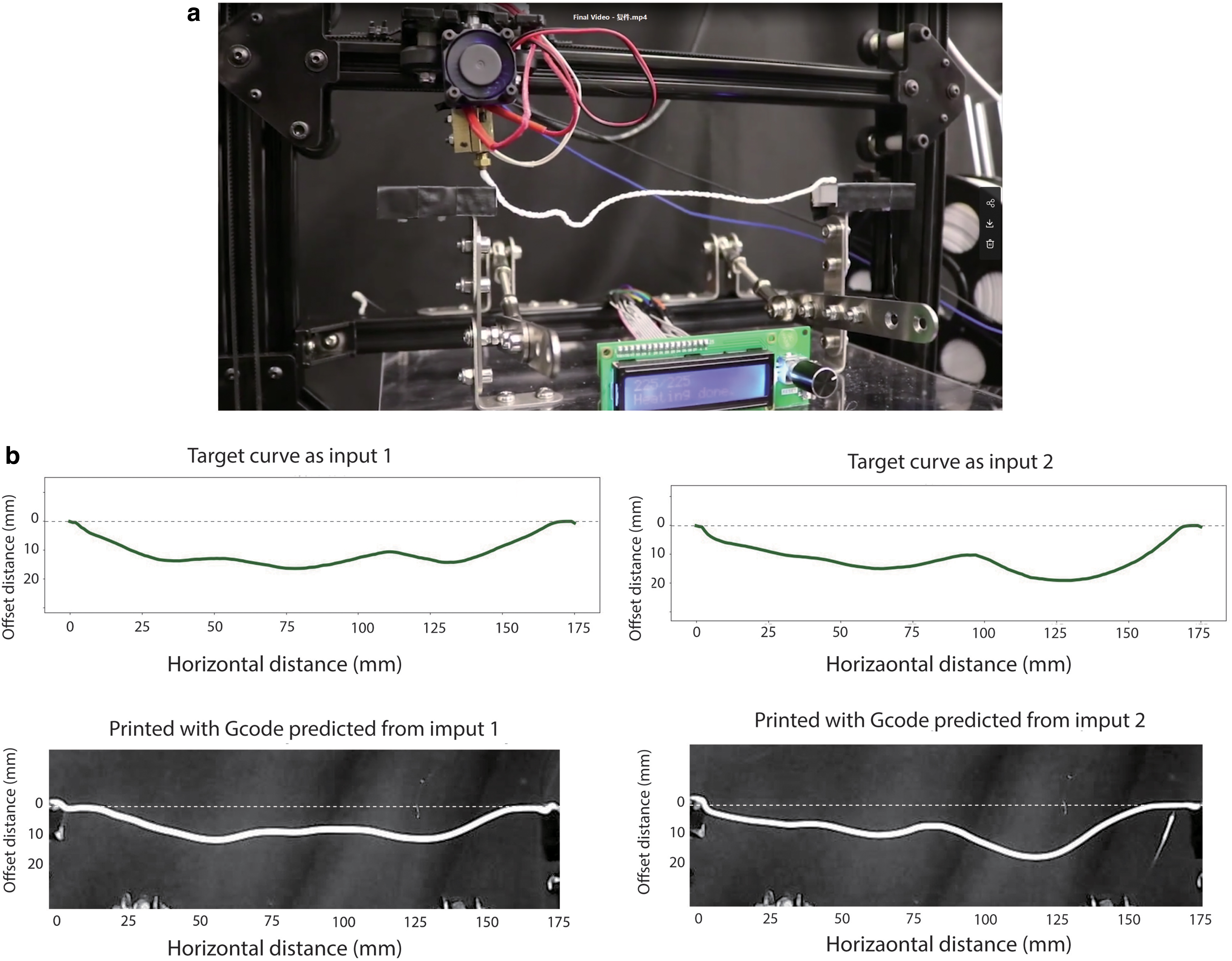
Although developed via robotic testing system, as the value of control parameters is collected in correspondence to the E and X values of a typical fused filament 3D printer, the NN model trained in this research can be adapted to a fused filament 3D printer via unit conversions and calibration. Thus, a practical application of this research is to expand the capacity of existing fused filament printer by enabling it to path plan and print 2.5D wireless frame simply by introducing a novel controlling algorithm. A prototype (Fig. 8a) that adopts the outcome of this research is developed by altering and adapting a low-cost 3D printer to print with the code generated via the code developed in this research. Figure 8b shows a few selected examples of curvatures printed with the low-cost 3D printer compared against the target curvatures that are used as input to generate the Gcode for printing.
Conclusions
Computing with the natural form-finding process of dynamic materials has long been a tempting idea in digital architecture design. This article presents our current progress on continuing research to combine AI and a mechanical automation process to generate an end-to-end material performance model that directly bridges the fabrication control and outcome form while utilizing complex dynamic material behaviors without requiring scientific understanding of the material properties. Inspired by the hand–eye–mind approach to crafting and materials, we explored the development of a universal method based on emerging technologies. This will liberate researchers and designers from technical constraints and from the need for in-depth knowledge of multiple professional fields, such as material sciences, that takes years to acquire.
By enabling design and fabrication with dynamic material behaviors that are beyond established systems, we developed an approach that is capable of utilizing dynamic material properties to realize more flexible and cost-effective fabrication. In this research, by replacing movement on the z-axis with control of the movement and extruder speeds, the challenge of printing a 3D spatial wireframe was achieved with 2D planar movement of the end-effector. This avoided the typical challenge of collision for 3D spatial printing. Movement along the z-axis was achieved by controlling the movement and extruder speeds. This method has clear potential to empower a typical FDM 3D printer for PLA to expand its capacity to printing 3D spatial wireframes with minimum modification of the hardware.
Footnotes
Authors' Contributions
D.L. conceived the presented idea, developed the theory and performed the computations, and drafted the article. W.X. provided the funding for this research, verified the analytical methods, encouraged D.L. to continue the investigation, and supervised the findings of this work. Both authors discussed the results and contributed to the final article.
Acknowledgments
The authors are sincerely grateful to Jingsong Wang, Dechen Chen, and Guanqi Zhu for their contribution in developing early prototypes and collecting data sets.
Author Disclosure Statement
No competing financial interests exist.
Funding Information
The authors gratefully acknowledge the financial support provided by the National Natural Science Foundation of China (NSFC) (project no. 51538006).