
Abstract
This article proposes a support diminution design method for layered manufacturing of manifold surface based on variable orientation tracking (VOT). We aim at reducing the external support or upholders to a minimum with maximum possibility theoretically to save material and diminish material stripping effect (MSE), thereby improving the bilateral surface precision either exterior or interior. The cosmic gravity effect criterion is first used to extract surface need support from manifold surface with various materials by considering the balance force involving material characteristics and inclination angle. In the light of this criterion theory, varying the substrate normal orientation (SNO), namely workbench, for each layer in printing coordinate system, may break the balance between gravity and its equilibrium force. Therefore, the optimal SNO can be rigorously calculated using mathematical harmonic analysis among the continuous domain. To serve for the multidegree of freedom (DOF) on account of SNO, a reconfigurable VOT robot with six-axis DOF is developed for 3D printing (3DP). The matched servo controller is successfully implemented to accurate tracking of both orientation and Cartesian coordinates, using forward kinematic chains as well as reverse kinematic tracking. What is more, the end-effector (extruder) is holding perpendicular to the substrate workbench. The physical experiment that takes human external ear auricle, for example, using a layer-based process is implemented via VOT. The MSE due to supporting material can be clearly observed and diminished using an optical microscope. The stripped material from external support via diminution design can be evaluated quantitatively by electronic weighting balance. All of which indicate the findings that external support in 3DP can be virtually reckoned and diminished using VOT rather than the so-called build orientation traversal method. The VOT method upon which we touched can be widely applied to various layered manufacturing of accurate structure, for instance, cantilever, sandwich, and scaffolds in the occasion needing precise curtailment of outer support multimaterial.
Introduction
The 3D printing (3DP) or additive manufacturing (AM) fundamentally uses a material additive process through which products are built on a mostly layer-by-layer basis, via a series of cross-sectional slices, using potential external support structures in general cases, origin from the whatever geometry manifold model. 3DP uses discrete materials such as liquid, powder, granule, and filament to accumulate layers based on the 3D CAD metadata of the object, and relies on the bonding force between the materials to finally produce the diversified object, using various techniques that include fused deposition modeling (FDM), stereolithography appearance, selective laser sintering, selective laser melting, laminated object manufacturing, digital light processing, continuous liquid interface production, and so on. All the manufacturing process is generally carried out on the Earth whereon the cosmic gravity effect (CGE) affects everything.
The last centuries have unconsciously seen a steady increase in average human life expectancy all around the world, particularly due to the advances across antibiotics, vaccines, availability of better health care, and improved hygiene. There exist a huge market and demand in transplantation and reconstruction of organs.1–3 And the typical way to do that is possibly bio-3DP or bio-AM4–6 for tissue engineering (TE), such as scaffolds, stents, artificial skin, and prostheses. The increasing requirements on fabrication of issues and even intravital organs worldwide are putting forward a higher request to the original design.
Minimizing external support is an important issue in 3DP to save materials and improve processing quality. Chowdhury et al. identified support facets with simple angle criterion. 7 Ezair et al. found that the volume of the support is a continuous but nonsmooth function, with respect to the orientation angles. 8 Extrusion-based bioprinting is a rapidly growing technology that has made substantial progress during the last decade. It has great versatility in printing various biologics, including cells, tissues, tissue constructs, organ modules, and microfluidic devices, in applications from basic research and pharmaceutics to clinics. 9 Stuart et al. defined and refined the concept of “printability” and reviewed seminal and contemporary studies to highlight the current “state of play” in the field with a focus on bioink composition and concentration, manipulation of nozzle parameters, and rheological properties. 10 3D-printed scaffolds and 3D bioprinting technique have the potential to develop a fully functional heart construct that can integrate with native tissues rapidly. Wassel et al. fabricated scratch-resistant nonfouling surfaces via grafting nonfouling polymers on the pore walls of supported porous oxide structures where the organic/inorganic nanocomposite films provide scratch-resistant antifouling surfaces. 11
Additional support structures are often needed, which leads to material, time, and energy waste. The external support might induce excessive material and energy consumption, meanwhile, reducing the surface accuracy, whether exterior or interior, and even upper surface and lower surface. Therefore, reducing the external support is apparently somewhat of a bottleneck and of great significance to improve the accuracy. Seepersad reviewed the advantages and developments of 3DP. 12 Habib presented an investigation on designing and fabricating possible scaffolds of a different internal structure with desired porosity and surface-area-to-volume ratio for TE by using FDM. 13 Mirdamadi presented a modified method of embedded bioprinting, which allows maintaining freestanding 3D-printed structures in cell culture conditions for extended periods of time. 14 Walker presented a framework for using isothermal curing kinetics and transient rheological data to 3D print a curing thermoset silicone without support. 15 Hildreth presented that overhanging surfaces often require support structures to be fabricated and minimize thermally induced distortion. Unlike polymer AM processes, soluble sacrificial support materials have not been identified and characterized for metallic materials, as a result, support structures in 3D-printed metals must be removed using additional machining operations. 16 Lefky demonstrated two approaches to dissolve supports. The approaches replace slow machining operations with fast electrochemical bath. 17 Ameen presented a segmentation strategy for the support. The strategy can reduce the support without reducing the accuracy of overhang. 18 Jiang et al. proposed a four-step strategy of multipart production for reducing support consumption. When printing a group of parts in the same build vat or chamber, the strategy optimizes the print orientation for each part, combines every two parts based on the geometries, proposes several possible multipart combinations, and then selects the optimal part positions for fabrication.19,20
The potential degree of freedom (DOF) of design offered by AM is, however, often limited when printing complex geometries due to an inability to support the stresses inherent within the manufacturing process. Many scholars have studied it from the perspective of geometric calculation theory. Di Angelo presented the objective functions of build direction and calculated the best direction for quality and support with the objective functions. 21 In addition, Llewellyn-Jones et al. proved the ability to automatically generate curved layer G-code tool paths for arbitrary shapes from a typical CAD model file, which are then printed with a Delta 3D printer. Experimental results showed the efficacy of using curved layers to improve the surface finish of a printed component. 22 Xu et al. presented a curved layer-based process planning algorithm for multiaxis printing of an arbitrary freeform solid part. 23 Chen et al. studied so-called curved layer FDM by allowing the sliced layers to have variable thicknesses and adjusting the build direction adaptively concerning the surface normal to print thin-shell models. 24 Most articles depend upon solely build orientation to improve accuracy, which is prone to impracticality, whereas the build orientation method seems ineffectual, in many cases particularly for holosymmetric body.
The traditional 3DP devices, such as the most basic XYZ printer and Delta printer, have only three DOFs. The printing nozzle is always perpendicular to the carrier platform, which makes it impossible to print when the printing platform is inclined at a certain angle. It is difficult for the 3-DOF printer to print complex models, especially in mechanical and medical fields. Inspired by computer numerical control and robotics, multi-DOF 3
These publications have more or less witnessed the development of 3DP for high-performance requirements. Nevertheless, there still lacks a theoretical method to diminish external support for 3DP of complex manifold surface. Therefore, based on our previous work,29–31
a support diminution design method for layered manufacturing of manifold surface based on variable orientation tracking (VOT) is herein proposed to reduce the external support or upholders to a minimum with maximum possibility theoretically. The VOT actually means adaptively varying workbench (carrier) normal for each layer to minimize external support till support-free 3DP considering interpolation smoothness using reverse kinematics via more DOFs. The VOT method is carried out on the 3
Printing Coordinate System of the Manifold Surface Model
The mechanical equipment for AM of manifold surface in the orthogonal printing coordinate system (PCS) is schematically shown in Figure 1. The equipment mainly includes the following: power system, electrical system, mechanical feeding system, carrier workbench, material feeding system, end-effector (EE) (nozzle), and so on. The maximum print strokes of a printer along
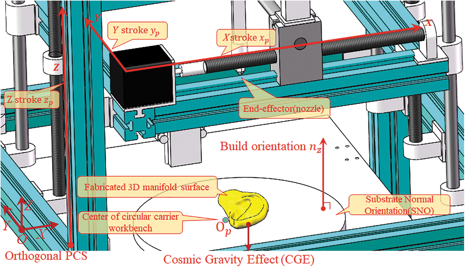
Mechanical equipment for AM of manifold surface in orthogonal PCS. AM, additive manufacturing; PCS, printing coordinate system.
The build orientation has an effect on precision, external support, and printing stroke. Hence, the factors that are affected should be considered in advance. For a nominal geometry, namely polyhedron manifold model M in R3 to be fabricated, let Ai,
In PCS, abiding by predefined uniform build orientation, to slice the manifold model into planar layers, the normalized height hn of i-th layer can be calculated hereby to represent the normalized height of the layer:
The total area of surface
The enclosed volume
where
For extrusion-based or layer-based 3DP, there exists the inherent SE. The SE can be manifested by cusp height
where d is layer thickness, α is the included angle between the z normal vector
The layered volume Ve can represent the error in cubic space.
where
The layer thickness sequence
where diff means first-order forward difference, arbitrary
Obviously, for uniform slicing, layer thickness is equal to each other,
The adaptive slicing is generally realized via variable thickness using multiple criteria such as cusp height
where
External Support Structure of Overhang Material Due to CGE
CGE criterion to extract surface need support
In 3DP, materials can be accumulated without extra supporting structures (i.e., the model can support itself without causing deformation) whenever the material is enough to balance CGE. We hereby proposed CGE criterion to extract surface need support, from a more essential perspective, which satisfies the following:
where G is the material gravity (N), Fb is the balance force generated from material affected by many factors such as material characteristics and inclination angle. m is mass (kg), g is acceleration due to gravity (N/kg).
The geometric included angle between the model surface and its printing orientation is defined as inclination angle
As we all know, different materials have different properties of solidification strength and van der Waals' (VDW) force at even mesoscopic scale. The imbalance of VDW forces may result in surface tension. The surface tension of nonmetals is mostly smaller than that of metals. On the basis of volume of the fluid method in computational fluid dynamics, the material equations can be derived.
33
where scalar Fs is the surface tension force (N · m−2).
where
The surface tension Fs contributes most of the Fb in some common cases for most materials used in the 3DP, which include the following: acrylonitrile butadiene styrene, polylactide, polyvinyl alcohol, thermoplastic polyurethanes (TPU), polycarbonate, polyamide, acrylonitrile styrene acrylate copolymer, high-impact polystyrene, thermoplastic polymers, polylactic-co-glycolic acid (PLGA), and so on.
Herein taking commonly used PLGA and TPU for comparative instance, some of the physical characteristics of the two are similar, whereas others are quite different. For PLGA, the intrinsic viscosity is about 0.2–2.5 dL/g via an Ubbelohde viscosity meter, the viscosity-average molecular weight of PLGA and the number average molecular weight attain 1–40 w, and the dynamic viscosity
Accordingly, it is practicable to consider the differences in the properties of materials when designing printing parameters for AM using Eqs. (9–12). Therefore, compared with the inclination angle method, the proposed CGE criterion is more essential and more suitable for various materials (Fig. 2).
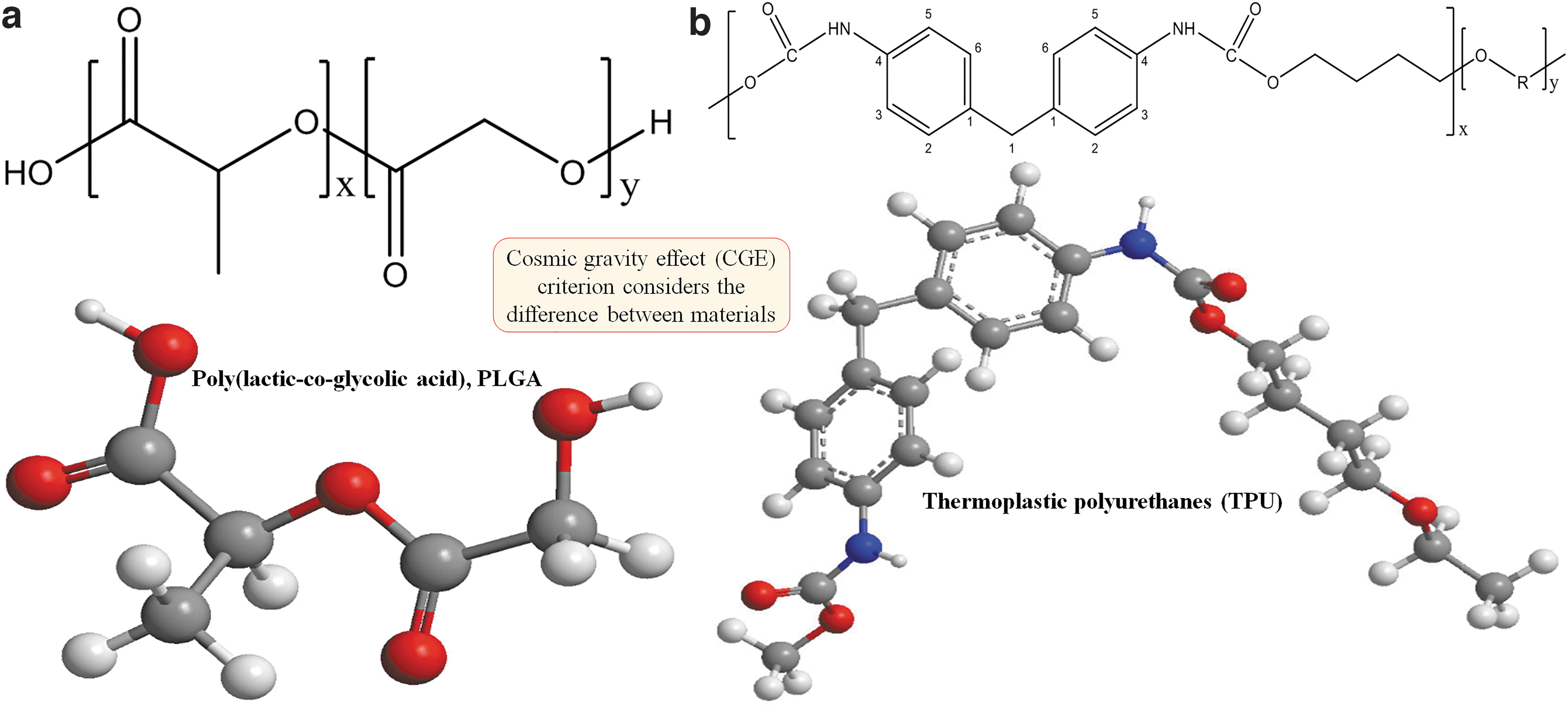
Balance force Fb is influenced by material property with distinctive molecular structure bonding diagram of PLGA
Determine the build orientation of each layer via principal component analysis
In the light of this criterion theory, varying the substrate normal orientation (SNO), namely workbench, for each layer in PCS may break the balance between gravity and its balance force. The optimization model can be built for each layer on the basis of Eqs. (9–12)
where
Academically speaking, the Fb for each layer is an infinite domain. It involves analytic mathematical programming methods, covering harmonic analysis, linear and nonlinear programming and multiobjective programming. And it is obviously difficult to find the optimal solution set precisely, just depends on the discrete method. Therefore, we propose and implement a method for calculating optimal solution in manifold surface by projecting high-dimension feature to low-dimension latitude feature of best fit using principal component analysis (PCA).
Let
where cov is covariance, card (Xi) = m,
The eigenvalue decomposition algorithm is used to obtain eigenvalue and eigenvector of covariance square matrix C. The calculated eigenvalues are ranked and the s largest eigenvalues are picked. The eigenvectors corresponding to the eigenvalues are also selected and combined as U.
where Y contains the s dimension data of the original vector. On the basis of Y and Fs, the appropriate vectors are calculated. Thus, normal orientation
Feasible solution ratio of each layer
For each layer in 3DP, after PCA manifold learning using Eqs. (14 and 15), herein we propose the feasible solution ratio
where
Innovatively, the
Variable Orientation of Each Layer to Minimize External Support
Overall conceptual design to realize variable orientation and thickness
It is common knowledge that the simplest and typical 3

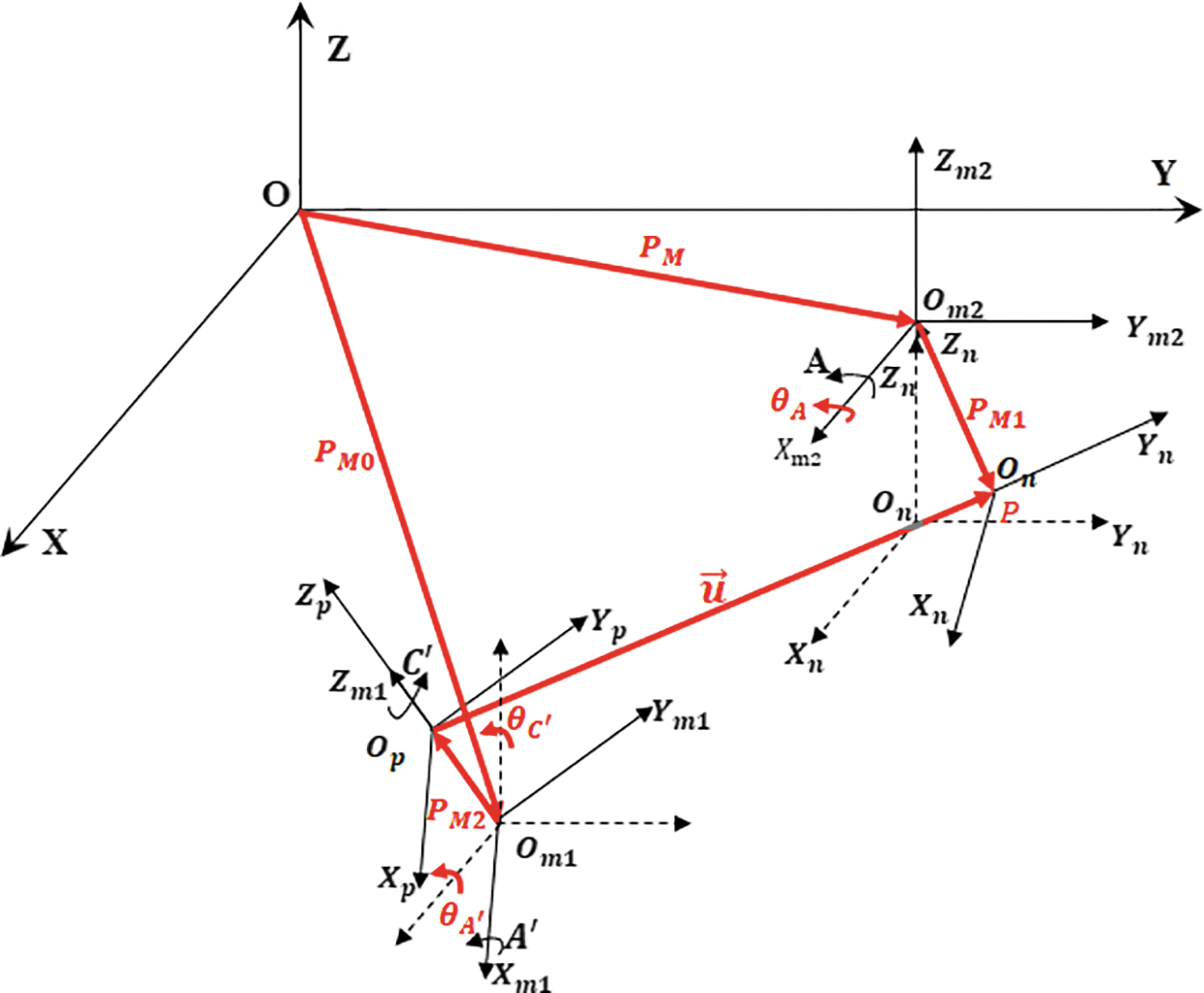
Coordinate systems of VOT robot where
Note that
It is assumed that the initial state of the printing robot is that the EE support CS is at the origin of
Let EE length
In
Establishment of kinematic chains of VOT robot with six DOFs
Let
The expressions of the direction vector of the EE and the position coordinates of the EE in
The kinematic chains corresponding to the position
Recursive homogeneous coordinate transformation of VOT robot
The transformation formulas corresponding to the coordinates
where
Where
Where the homogeneous coordinate matrix of
where the homogeneous coordinate matrix of
Where the homogeneous coordinate matrix of
The homogeneous coordinate matrix of
Through matrix operation, the expressions of direction vector
The homogeneous coordinate transformation equations of translation and rotation Eqs. (18 and 19) are all depicted by nonsingular matrix:
Kinematic equations of VOT robot
Substituting the homogeneous transformation matrices into Eq. (19), the coordinate transformation equations of the VOT robot can be obtained as follows:
Based on the mechanical structure of the VOT robot, the corresponding mathematical model is established and expressed in the form of a CS and kinematic chain group. The coordinate transformation equations of position and pose
VOT via Reverse Kinematics of Six-DOF Robot
Prioritized quadrant projection for unique reverse kinematics
To determine the unique exact solution of the VOT robot, the prioritized quadrant projection (PQP) judgment criteria are proposed.
If the obstacle avoidance requirement of the printer relative to the movement of the EE is not yet considered, the unique orientation solution can be obtained by the three steps.
First step, with the highest priority, according to the
Second step, the angle
Third step, according to the method of solving nonhomogeneous linear equations, the unique orientation solution of the 3D space motion control parameter
Unique optimal solution of rotation control parameter
of carrier platform
The quadrant position of
Prioritized Quadrant Projection Judgment of
As shown in Figure 5a,

Prioritized quadrant projection judgment criteria are proposed to obtain a unique orientation solution of reverse kinematics of VOT robot.
Then:
So far, the unique optimal solution of the rotational control parameter theta
Swing angle
of EE and the swing angle
of supporting platform
The angle
According to the solution principle of swinging EE before swinging hotbed workbench, the parameters are obtained as listed in Table 2.
Prioritized Quadrant Projection of Tracking Control Parameters
Note: According to the requirement of the posture of the EE,
So far, the unique orientation solution of the swing control parameter
Tracking spatial location of EE support
After obtaining the unique orientation solutions of
The final solution of
By orderly assembling the tracking control parameters of EE among all layers of a 3D-printed object, each DOF can be obtained to drive the machine. Combining with the specific motor drive control mode, the parameter set of motor motion control can be obtained with different accuracy.
After reverse tracking, the Cartesian coordinate trajectory P in PCS (shown in Fig. 4) of each layer can be obtained precisely for 3DP. For arbitrary
To further improve the surface quality of the printed model, nonuniform rational B-spline interpolation can be used between adjacent layers to improve manufacturing efficiency.
Numerical Example of 3D Manifold Surface
Variable orientation of manifold surface model
Cochlear implant is recognized as an effective bioelectronic medical equipment to provide a sense of sound to totally severe deafness for restoring or reconstructing deaf people's hearing. The auricle is a highly directional sensitive reflector, and therefore, the surface roughness has an important influence on the perception and location of sound source for a human being. For sound waves with a frequency of about (2, 3 kHz), the wavelength may be close to the auricle size, only then does the auricle begin to collect sound waves. For the sound waves with a higher frequency of about (5, 6 kHz), the auricle's spatial positioning function appears to be obvious. Figure 6 indicates medical magnetic resonance imaging and a regenerated human head with an external ear auricle structure.
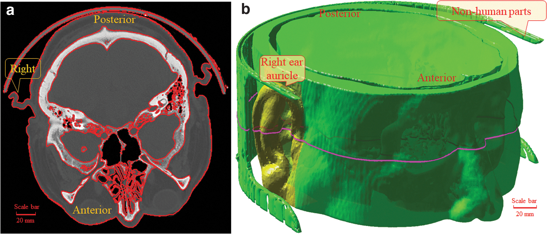
Medical magnetic resonance imaging
The to be printed model is human external ear (right ear in Fig. 6b) with a complex surface, which is concerning either the exterior or interior surface. It has no geometric symmetry by itself. The size in Y direction, namely auricle size is 59.14 mm (mm, hereinafter inclusive). The stroke ratio in x,y,z direction of AABB is 2.1005:3.1159:1. The total surface area
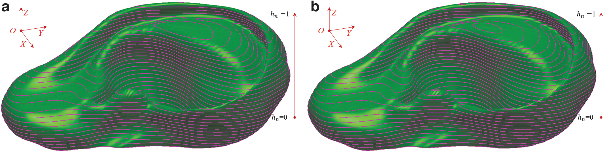
Comparison of uniform and variable geometric slicing of human external ear using same total layers where
Figure 8 shows comparisons of cross-sectional area and volume of each layer of external ear (shown in Fig. 7) under the constraint of same layer amount. About the cross-sectional area in Fig. 8(a), the maximum is optimized from 9.423057e+02 at 31.0345% to 9.422570e+02 at 31.0345%, the minimum is optimized from 1.901384e+01 at 100% to 2.044865e-02 at 100%, and the mean value is optimized from 681.6599 to 674.4360. About volume shown in (b), the maximum is optimized from 6.726971e+02 at 27.5862% to 6.386996e+02 at 31.0345%, the minimum is unchanged, and the mean value is changed from 456.9531 to 457.1288. The trend of the cross-sectional area and volume is similar but not the same, which proves that the layer thickness varies.

Comparison of cusp height of each layer for external ear under same layer amount
Figure 9 demonstrates feasible solution ratio
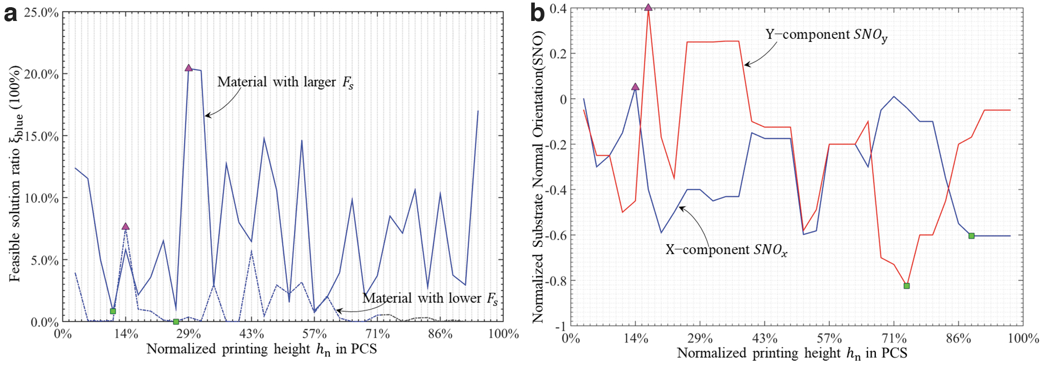
Variable SNO of each layer for external ear where
Meanwhile, in Figure 9b, the blue curve indicated about
The full continuous domain of the SNO can be figured out by using polar coordinates instead of Cartesian coordinates. Figure 10 shows nondiscrete continuous SNOs of schematic four layers in a normalized circular workbench. Note that the solved blue or red regions are concordantly continuous, which proved a continuous analytical calculation without discretization. About (a),
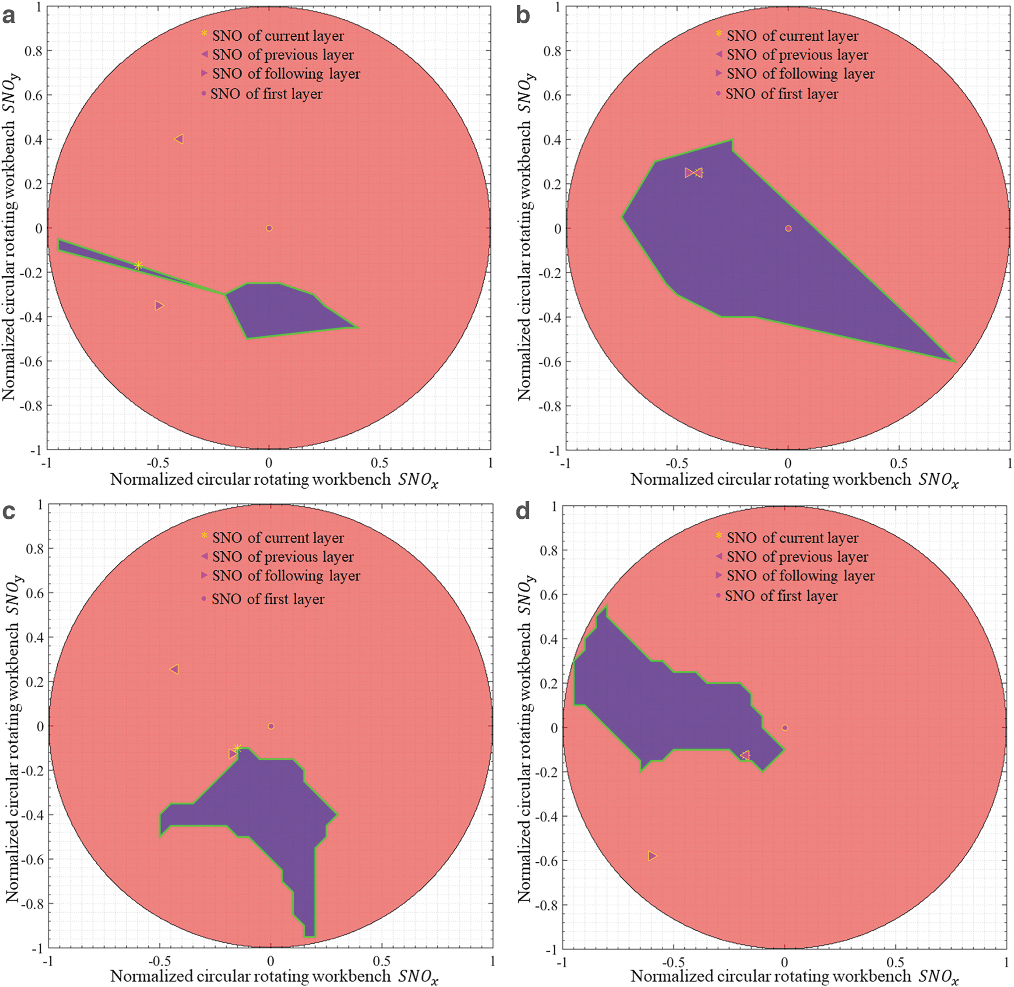
Nondiscrete continuous SNOs of four layers in normalized circular workbench where blue region means without external support, whereas red region means indispensable external support.
Kinematic parameters of six-DOF 3DP system
Herein we completed the prototype design of six-DOF 3DP system conceptually, shown in Figures 3–4. By adding extra three DOFs on the traditional three-DOF printer, the workbench orientation can be adjusted to minimize upholders for each layer. Prior to any reverse tracking computation, the mechanical parameters should be predefined to clarify the range of tracking control parameters listed in Table 3. (The rotation direction is determined according to the right-hand helix rule.)
Range of Parameter Variation of Variable Orientation Tracking Robot
EE, end-effector.
By iterative convex optimization, all layer tracked orientation angle of six-DOF robot is shown in Figure 11. About rotational parameters with
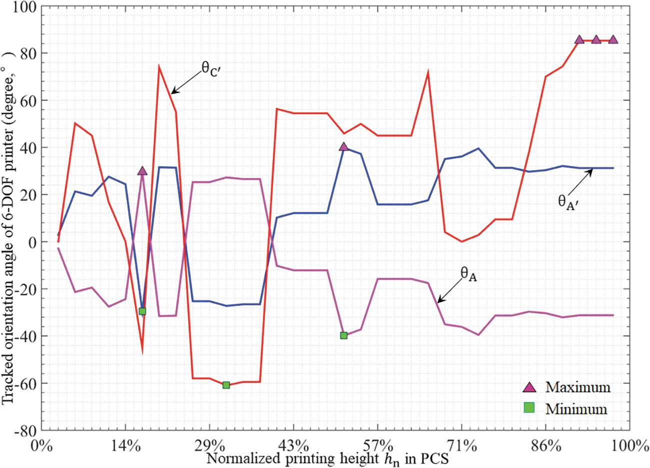
All layered normalized SNO and its tracked orientation angle of six-DOF robot. DOF, degree of freedom.
Figure 12 exhibits the layered trajectory to be tracked of different layers in MCS. About (a), the loop amount is 141, the total trajectory length is 1847.3317 with point amount
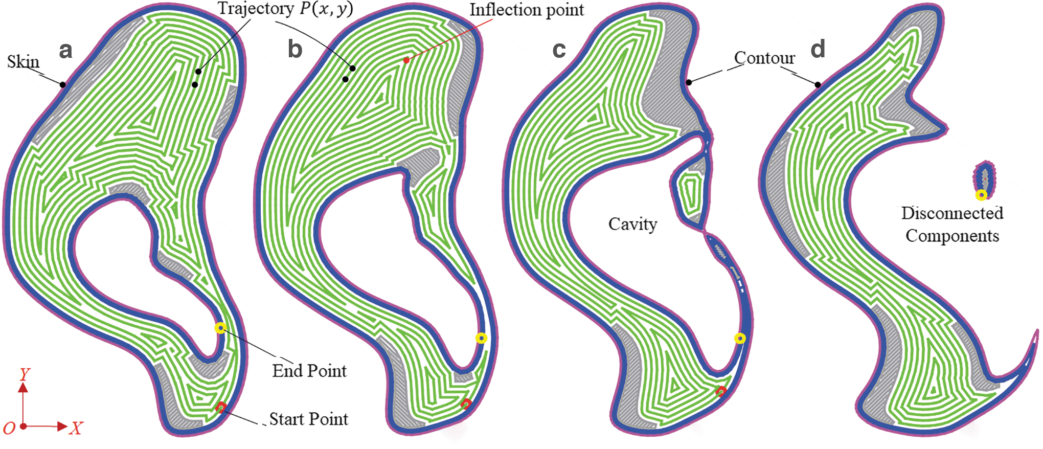
Layered trajectory to be tracked of different layers in MCS with
VOT of the manifold model via six-DOF 3DP printer
Based on the VOT method, the reverse tracked contour trajectory in PCS of different layers is shown in Figure 13. The tracked results are all with Cartesian coordinates instead of rough shape, which manifest the systematic and rigorous superiority of the proposed VOT. In arbitrary given layer, the Z coordinate varies instead of being a constant, which proves that the build orientation is variable layer by layer. The translational parameters
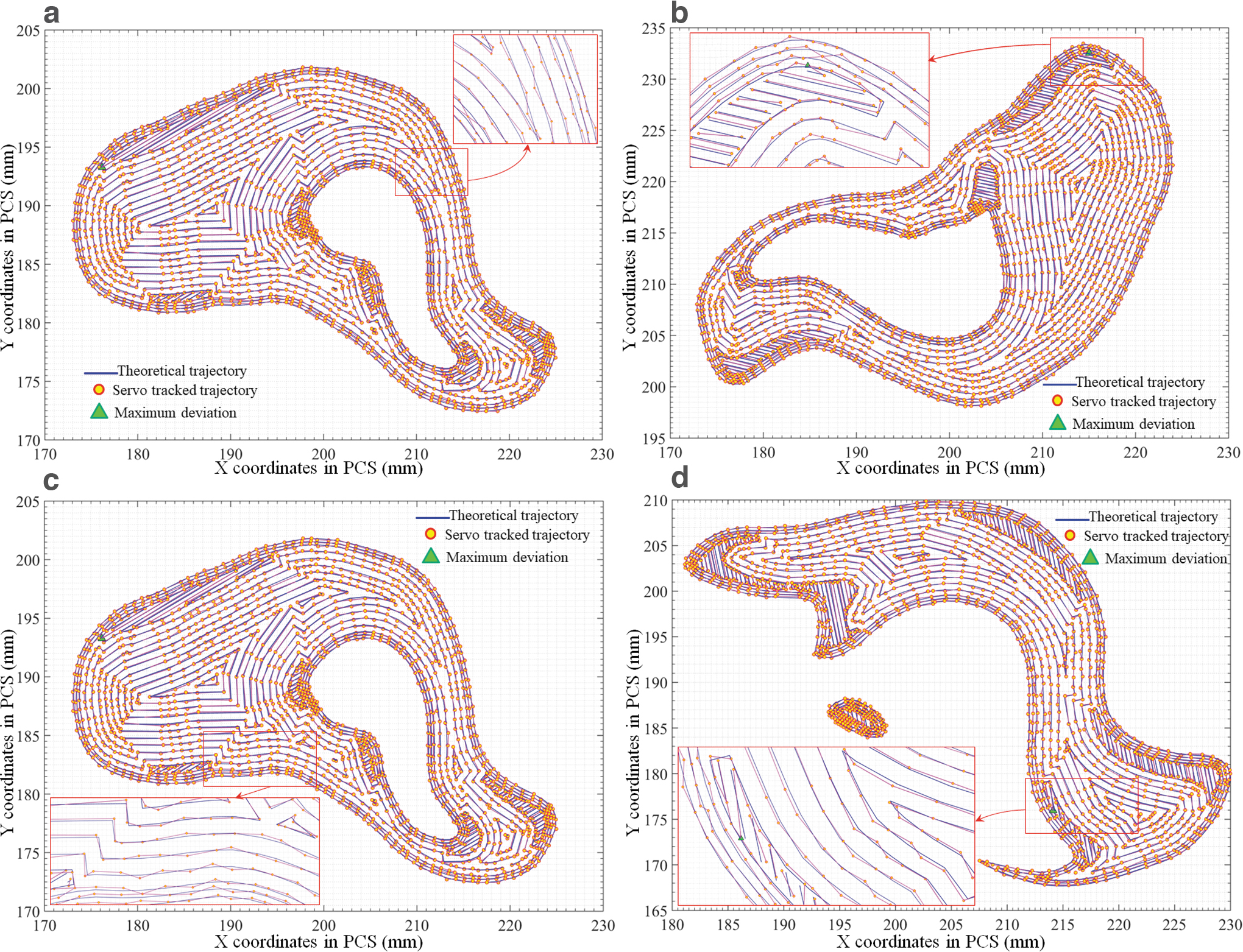
Reverse tracked contour trajectory of different layers in PCS where
The kinematic simulation of the proposed VOT robot can be further verified using multibody dynamics software ADAMS™. The simulation time can be 60 s and the simulation step size can be set as 0.1 s. The amount of simulation points should be in accordance with
The process of fabricating manifold surface using six-DOF robot via VOT is shown in Figure 14. The tracked orientations can be validated by Figure 11. It is important to note that the EE (extruder) is holding perpendicular to the substrate workbench, which reflects the accuracy of inverse kinematic calculation.

Fabricating manifold surface using six-DOF robot via VOT where
VOT result comparison
Beware that the external support structure varies multifariously, for instance, cylinder type, tree type, fractal tree type, and bionic structure. Herein we use the typical cylinder type to evaluate the surface need support, which is akin to feasible solution ratio
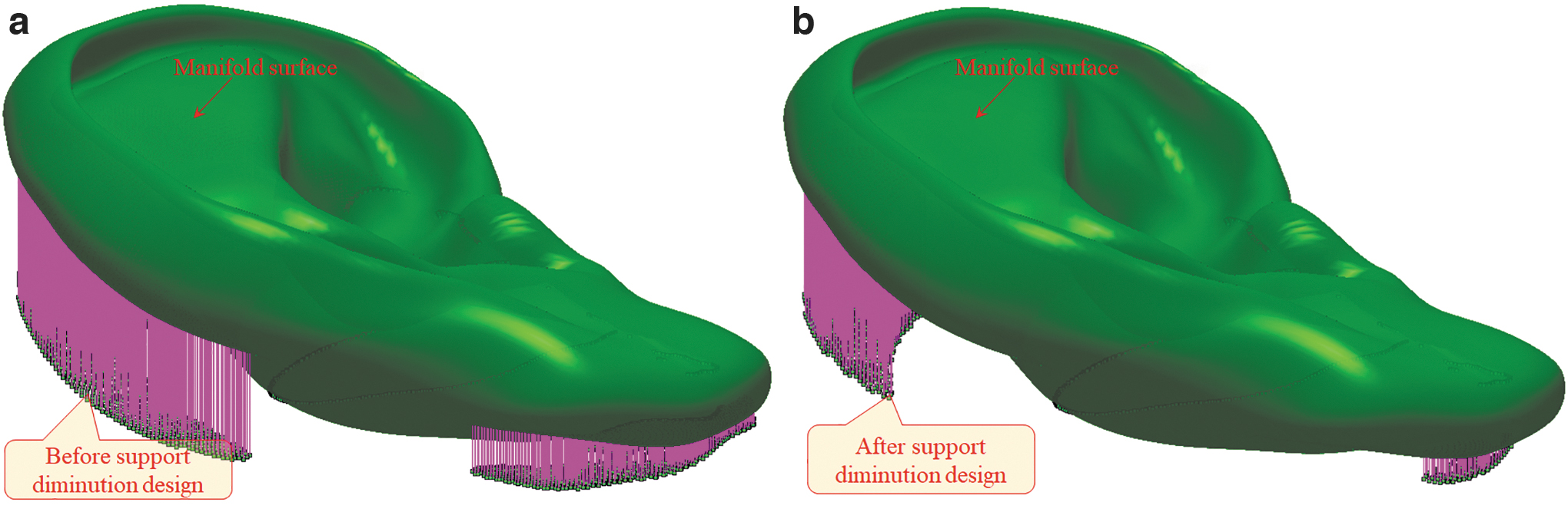
Comparisons of external support material consumption where
Physical Experiment of VOT Printing
Physical fabricating via extrusion-based AM
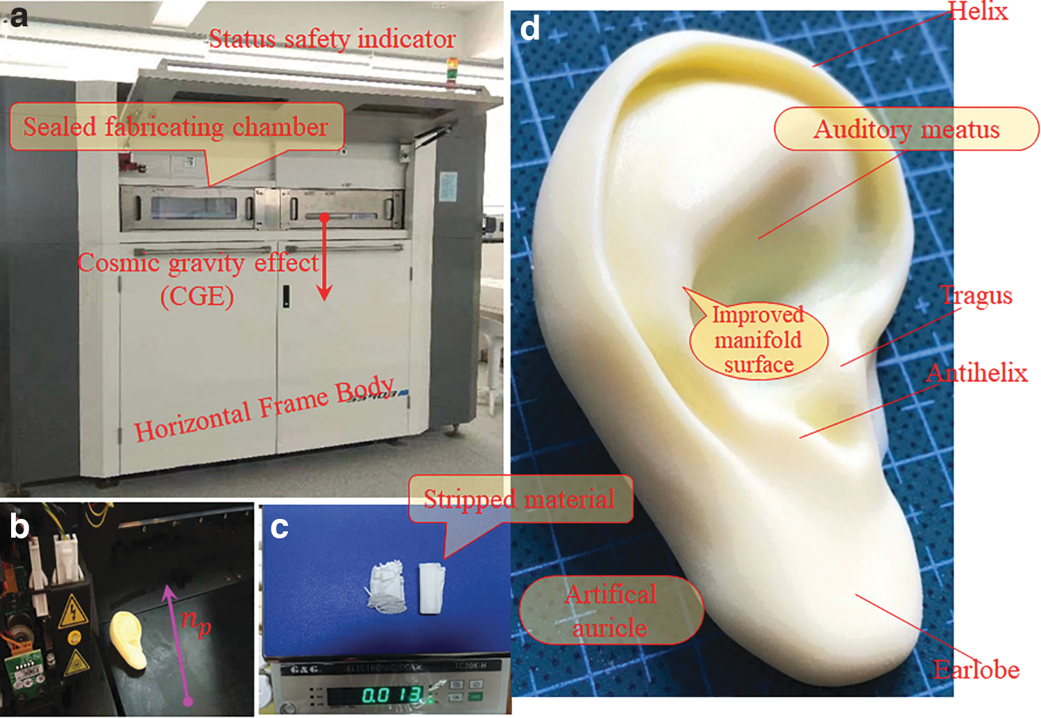
The stereolithography apparatus is extrusion-based manufacturing. The desktop apparatus size is relatively larger than the maximum space. The layer thickness can be as small as 0.02, 0.05, 0.1 mm. The resolution precision size in X/Y direction can be 0.1 mm. The power supply is alternating current (AC) 220 V. The ambient temperature is 25°C with 55% relative humidity. The nominal voltage electrical motor for rotating DOF is direct current (DC) 24 V. The printing process using extrusion-based 3DP is shown in Figure 16a and b. The stripped material from external support via diminution design can be evaluated quantitatively. The material weight (mass) has been measured by an electronic weighting balance using high-precision strain-type weighing sensor with antielectromagnetic interference, shown in Figure 16c. As is known metrology to all, the capacity range and resolution are two contradictory and mutually restrictive indexes. Herein the capacity is 1 kg, meanwhile the resolution ratio is 0.1 g (1‱), maximum permissible error 0.2 g, whose power supply is nominal AC 230 V ± 10% 50 ± 1 Hz 4 W or DC 6 V/4 Ah/20 HR rechargeable battery. Regarding the communication functions, it can connect with computer to collect and calculate data or support remote control to generate ASCII text file, using standard RS 232C serial bidirectional data communication interface (16 pins), with Baud rate 600-9600. The photograph (Fig. 16d) in macromode qualitatively revealed the effect of material stripping on the fabricated surface.
Fabricating process for high surface accuracy where
Manifold surface precision measurement
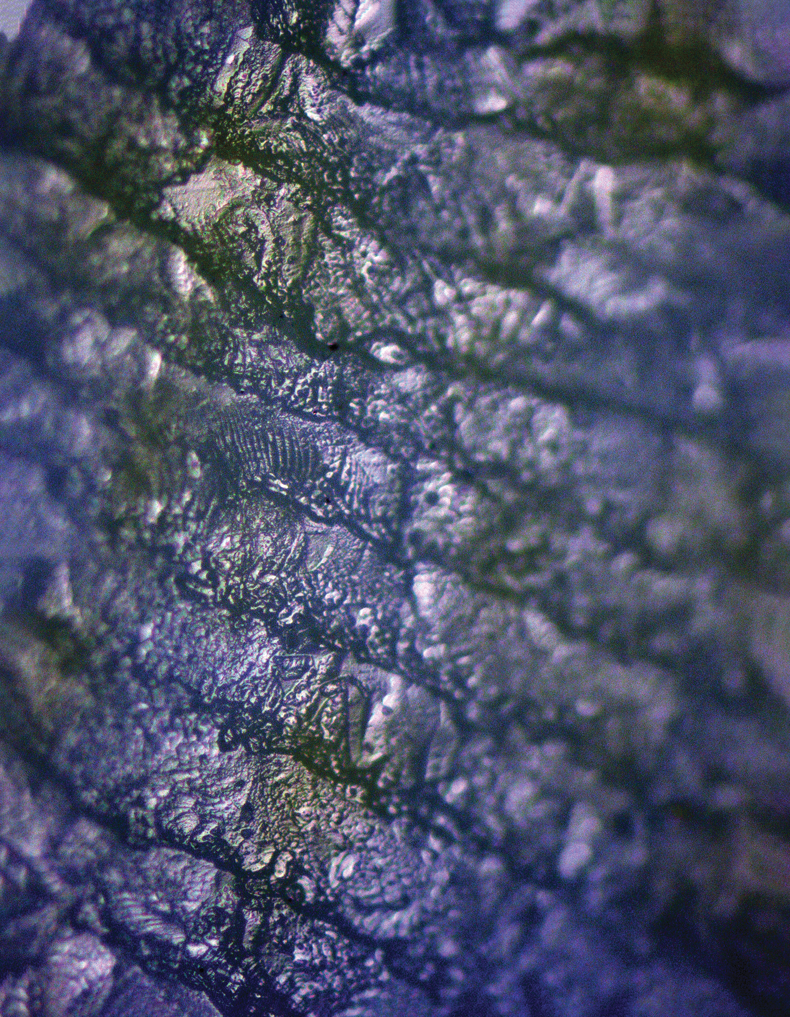
The surface roughness of the 3DP fabricated specimen can be measured by surface profilometer, either an optical microscope (OM) or EM. The wavelength of visible light ranges about 380–780 nm. Optical methods of measuring surface roughness have many advantages such as imaging stability, rapid response, noncontact, nondestructive, and area-averaging. Hence, we use the OM (Label.1) to observe and evaluate material stripping effect (MSE) with distinct sampling regions. The relevant physical experiment of material surface topography is shown in Figure 17. The specimen (Label.4) is insulating with big enough electrical conductivity.
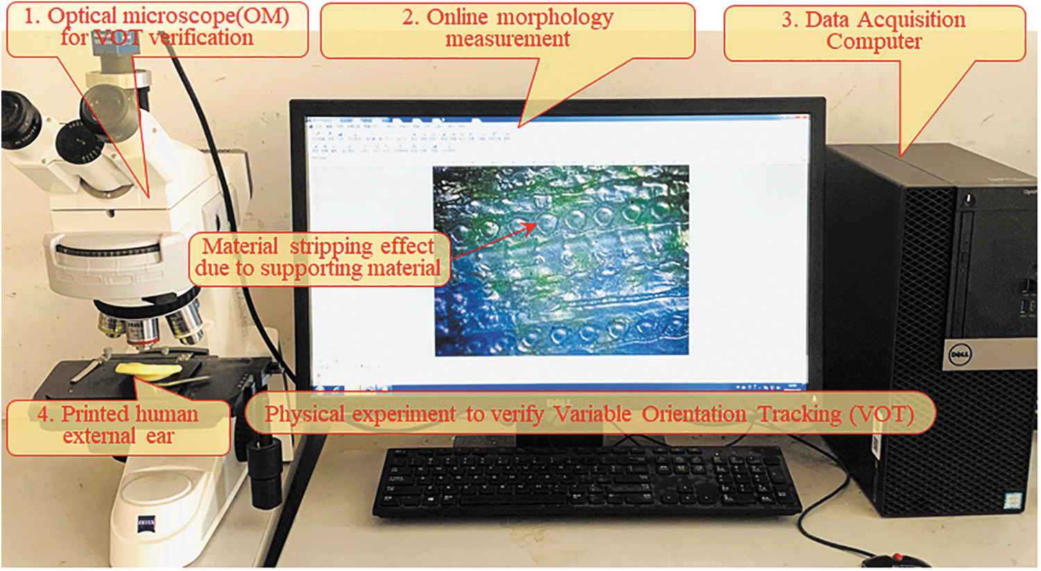
Physical experiment of material surface topography using OM. OM, optical microscope.
During measurement via using OM, a little bit different from the scanning electron microscope, the region should be approximately 2D planar, Otherwise, the focus area will be reduced, dues to incomplete spotlight. The measured surface topography comparison of the fabricated specimen using OM is shown in Figure 18. The MSE due to supporting material can be clearly observed. The slight defocus of the image nicely proves that the region being photographed is rather a curved surface than a plane. By external support diminution design, the vast majority of surface can be optimized (decreased) from at least about Ra 12.469 μm to no more than Ra 7.681 μm.
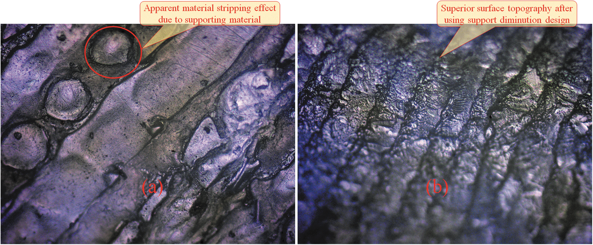
Surface topography comparison of the fabricated specimen using OM where the magnification is 100 × times for either before
Innovation comparison
The innovation comparison between the others' published articles and the proposed VOT method is conspicuously listed in Table 4.
Innovation Comparison Between the Published Articles and the Proposed Variable Orientation Tracking Method
AM, additive manufacturing; CGE, cosmic gravity effect; DOF, degree of freedom; MSE, material stripping effect; PCA, principal component analysis; SLA, stereo lithography appearance; SLS, selective laser sintering; SNO, substrate normal orientation; VOT, variable orientation tracking.
Conclusions
Support diminution design method for layered manufacturing of manifold surface based on VOT is proposed
The CGE criterion is first used to extract surface need support from manifold surface with various materials by considering the balance force such as material characteristics and inclination angle. The CGE criterion lays a theoretical foundation for the VOT method. This CGE criterion may inspire more following research because of its profound commonality and adaptability. The important scientific discovery is that varying the SNO, namely workbench, for each layer in PCS may break the balance between gravity and its equilibrium force. The optimal SNO for each layer is calculated using continuous mathematical harmonic analysis on surface. The external support in 3DP then can be exactly calculated and reduced based on rigorous mathematical theory to reduce external support or upholders and further to protect the manifold bilateral surface. The proposed method can be reversely used to evaluate the build orientation in terms of external support material metering. This article facilitates fabricating high-precision multimaterial 3
A reconfigurable VOT robot with six-axis DOF and the matched servo controller are developed simultaneously for 3DP
A reconfigurable VOT robot with six-axis DOF is developed for 3DP. The forward kinematic model of the six-DOF 3DP robot is built via recursive homogeneous coordinate transformation considering the RTCP effects. The PQP judgment criteria are presented to obtain a unique orientation of reverse kinematics of VOT robot. What is more, the EE (extruder) is holding perpendicular to the substrate workbench. The accuracy between the original theoretical trajectory and the reversely tracked trajectory points can be distinctly adjusted by using various electrical servo drive step sizes. The VOT results are given with coordinate values in PCS, which enhances and highlights the rigor of scientific computation process.
The physical experiment of manifold surface 3DP using layer-based process is implemented using VOT
The physical experiment, which takes human external ear auricle, for example, using the layer-based process, is implemented via VOT. Moreover, the physical experiment involves material property experiment, material roughness experiment, mechanical servo drive test, position and orientation measurement, and so on. The MSE due to supporting material can be clearly observed and diminished using OM. The stripped material from external support via diminution design can be evaluated quantitatively by the electronic weighting balance. All of which indicate the findings that external support in 3DP can be putatively reckoned and diminished using rather VOT than the so-called build orientation traversal method. The covering surface area of the external support is reduced with a ratio of up to 32.66%, and the mandatory consumed material of the external support is reduced with a ratio of 69.62%. The proposed method provides a relatively scientific quantification for minimizing external support material rather than the so-called support-free concept. It can be expectantly applied to various AM of more accurate 3D manifold structures such as cantilever issues and even intravital organs.
In future, the VOT method and its machine prototype robot will be developed toward high performance with intelligent adaptation, together with printing more complex manifolds, mechanical parts, and surface curved thin end-use objects. We expect this VOT approach will promote and arouse more ongoing research, which spans intelligently adaptive slicing, multimaterial external-supporting diminution, geometry trajectory generation, infill structure topology optimization, and even electromechanical control.
Footnotes
Authors' Contributions
J.X. initiated the essential innovations and finalized the article. M.G. carried out the analytic mathematical programming and theoretical computation among the continuous domains. X.F. participated in the mechanical precision experiment. Z.S. developed the six-DOF robot and relevant matched servo controller. K.W. verified the feasibility and practical superiority of diminishing material. S.Z. guided the team research as PI (Principle Investigator). J.T. made constructive suggestions to the work as Chief Scientist. The all metadata of ![]() are shared for the readers for verification or calculation.
are shared for the readers for verification or calculation.
Author Disclosure Statement
No competing financial interests exist.
Funding Information
The work presented in this article is funded by the National Natural Science Foundation of China (nos. 51935009; 51775494; 51821093), the Zhejiang Provincial Research and Development Project of China (no. LGG21E050020), and the National Key Research and Development Project of China (no. 2018YFB1700701).