
Abstract
Over the past two decades, electrospinning has emerged as a common technique to produce biomedical scaffolds composed of ultrafine fibers formed from many natural and synthetic polymers. A major advantage of this technique is the ability to produce scaffolds that resemble the native extracellular matrix in physical, chemical, and topological properties. However, scaffolds fabricated via electrospinning are not formed with a controlled architecture and typically do a poor job of directing cell growth into prescribed structures for tissue/organ development. To address these weaknesses, 3D bioprinting has recently been used to develop scaffolds that have a highly organized and precise global topology. Unfortunately, these 3D bioprinted scaffolds do not typically resemble the native extracellular matrix in physical properties, such as porosity, fiber diameter, and pore size (e.g., the microarchitecture). Thus, the goal of the current study was to develop a technique that harnesses the intrinsic advantages of both conventional electrospinning and 3D bioprinting techniques to produce scaffolds that have the potential to be used within biomedical applications. The physical properties of formed 3D printed electrospun scaffolds were compared with conventional electrospun and 3D printed scaffolds. Further, we conducted initial proof-of-concept biocompatibility studies to illustrate the applicability of the scaffolds within vascular applications. Our results illustrate that 3D printed electrospun scaffolds can be developed, via our technique, that have highly tailored and organized arbitrary geometries with scaffold properties in the range of the innate extracellular matrix. In addition, these scaffolds were shown to support endothelial cell growth. Therefore, we illustrate the development and testing of a novel bioscaffold fabrication technique that may be used for many tissue engineering and regenerative medicine applications, which allows for the direct printing of electrospun scaffolds into well-defined macro-scale geometries that also retain the micro-structures commonly observed in electrospun scaffolds.
Background
The fields of tissue engineering and regenerative medicine hold significant promise for future medical applications, by allowing for the design, growth, and optimization of tissue and organ structures ex vivo for repair or replacement of innate structures. However, this field has been limited by the inability to develop scaffolds tailored to specific applications. Further, these tailored scaffolds should support the growth of cells that are appropriate for the specific application and/or themselves be designed such that they can be incorporated into innate biological structures with limited inflammatory and thrombogenic responses.
Multiple scaffold fabrication techniques have been investigated over the past few decades. Although there has been success with various scaffold fabrication techniques, most engineered scaffolds still have significant limitations within their adoption for tissue engineering and regenerative medicine applications.1–4 We believe that these limitations can be addressed by developing novel techniques that aim at combining the strengths of individual fabrication techniques that have been investigated thoroughly to date. In this report, we aimed at directly combining conventional electrospinning techniques with 3D printing techniques to develop a porous scaffold formed in a prescribed non-filled geometry that resembles the native extracellular matrix in microarchitecture properties.
Electrospinning is a process that was originally patented in the 1930s as a means to develop small artificial threads from various polymers using electrical gradients.5,6 Since the original patent, many modifications of the electrospinning apparatus have been made to control the overall properties of the scaffolds or the properties of individual fibers. For instance, through the use of a rotating mandrel, scaffolds can be formed with fibers aligned in one direction.7,8 Further, coaxial systems have been developed, so that scaffold fibers can be designed with specific materials in the core section of the fiber with different materials composing the sheath of the fiber.9,10
Regardless of the fabrication technique, electrospinning produces highly porous fine-fibered scaffolds that are typically mechanically weaker than the native extracellular matrix, composed of fibers that are randomly deposited onto a collector and that have different mechanical interactions between the cells and the scaffold fibers. 11 Although there have been approaches to improve the mechanical properties of formed electrospun scaffolds, 9 the resulting overall mechanical properties only approach the lower end of the innate extracellular matrix. Thus, it is usually observed that electrospun scaffolds cannot direct and support cell growth into prescribed patterns and it is common for electrospun scaffolds to be too mechanically weak to support the growth of cells into tissue- or organ-like structures.
Extrusion-based 3D printing is a relatively new technique that has been applied to the production of biological scaffolds. A major advantage of 3D printing is that scaffolds can be formed with very precise and repeatable geometries.12,13 Many 3D printed scaffolds have been developed that perform well with respect to cell growth, with the cells either printed directly within the polymeric material or seeded onto scaffolds afterward. 14
3D bioprinting has been illustrated to have promise in tissue engineering and regenerative medicine applications.15,16 However, these scaffolds have limitations that are similar to pure electrospun scaffolds, in that the topological properties of formed scaffolds do not mimic the microarchitecture of the innate extracellular matrix, and typically the resolution of features that can be 3D printed are on a much larger scale than that of the innate extracellular matrix. 17 Under ideal conditions, inkjet and extrusion-based bioprinters can approach a resolution of 50 μm, which far exceeds the size of typical extracellular fibers (in the range of 10 s of nanometers) and the size of an average biological cell (∼10 μm). As described earlier, there is a need to improve on both the electrospinning and 3D printing techniques for successful biomedical applications.
In the past, there have been reports on combining electrospinning techniques with 3D printing techniques. These combinations have always been reported in a series layer-by-layer fashion, where one layer of a scaffold will be fabricated using one technique and then a second layer will be fabricated with the opposite technique.18–20 For instance, a vascular graft was fabricated from polydioxanone (PDO) electrospun onto a tube, followed by a layer of 3D printed poly-caprolactone (PCL), followed by a third electrospun PDO-PCL layer on the external surface of the scaffold. 21 Another report has shown that electrospinning can be used to prepare freeze-dried fibrous bioinks that were then used to produce 3D bioprinted scaffolds. 22 A third report discusses the 3D bioprinting of a PCL layer, followed by a PCL electrospun layer, followed by a third 3D printed PCL layer. 20
A recent report illustrates the use of computer-controlled motors to print electrospun scaffolds 23 ; however, the final scaffolds produced with this method were still completely filled, resembling conventional electrospun scaffolds. This report 23 used rigid plastics to “frame” the overall shape of the electrospun scaffold, but did not illustrate the ability to pattern a pure electrospun scaffold into an arbitrary geometry.
We report here a method that combines the electrospinning and 3D bioprinting process into a single process aimed at harnessing the strengths of 3D printing (e.g., well defined macro-structures) and electrospinning (e.g., highly porous small diameter scaffold constructs). Formed scaffolds from the reported technique can have an arbitrary macroarchitecture while retaining the electrospun microarchitectures within the printed structure. Scaffolds produced from this technique can potentially address biomaterials needs, where a highly organized macroarchitecture that is composed of microarchitectures that resemble the native extracellular matrix are required.
Methods and Materials
Electrospinning
PCL (MQ200, average molecular weight 80,000, note that all chemicals were purchased from Sigma-Aldrich, unless otherwise noted) was dissolved in acetone at a 5% or 10% weight/volume solution and was used for all conventional electrospinning experiments. Electrospinning scaffold fabrication is a function of distance from the tip of a small gauge needle (20G used here) to a collector plate, the voltage gradient over that distance, and the flow rate of the polymer solution being extruded from the needle. For this work, we matched all applicable parameters between our three techniques to allow for a comparison between the formed scaffolds. Here, we fabricated electrospun scaffolds with a 3 kV/cm voltage gradient (Model MK30P2.5, Glassman High Voltage), over a 3 cm distance at a flow rate of 300 μL/min (Model WPI SP 220I). All electrospun scaffolds were collected directly onto aluminum foil for easy sample sterilization post-electrospinning.
3D printing
Ten percent weight/volume PCL (in acetone) was printed using a Tissue Scribe (3D Cultures, Philadelphia, PA). Scaffolds printed with this technique were made with a linear-arrayed geometry with uniform spacing of 400 μm. The PCL/Acetone solution was heated to 70°C and extruded through a 32G needle at a feed rate of 2.5 mm3/s. These scaffolds were printed directly onto glass coverslips (40°C) for easy sample collection, sterilization, and use within cell culture applications. Scaffolds were printed at a linear rate of 0.5 mm/s. The tip of the extruder was brought to within 1 cm of the printing stage.
3D printed electrospun scaffold development and fabrication
To combine 3D printing and electrospinning, we needed to tune the conventional electrospinning parameters (as described earlier in the electrospinning section) so that the forming fibers do not disperse significantly from the nozzle during the printing process (note that in conventional electrospinning, in general, the further the needle tip is from the collector, the larger the area is for collection). Our system was developed from a customized and controllable 3D printing rail and stage (fabricated from 80/20 aluminum) system that was ∼45 cm square. Three computer-controllable stepper motors allowed for precise motions within the X, Y, and Z directions. The motors were connected to an Arduino Uno board and a gShield v5b complex for computer control. Motor motions were programmed using Universal G-Code and sent to the motors. All motor motions were tested for accuracy before printing.
The stage of this system was placed at a distance of 3 cm from our steel collector plate (aluminum coated), and a 20G needle was clamped onto the stage. The needle was connected to a syringe pump to control the polymer extrusion at a rate of 50 μL/min; the stepper motors were controlled so that the needle would move at a rate of 0.5 mm/s (tangential velocity along the pattern). Our voltage supply was connected to the collector plate and the needle at a voltage gradient of 3 kV/cm. Figure 1 illustrates the customized system to produce 3D printed electrospun scaffolds. Overall, we aimed at fabricating a scaffold with a prescribed macroarchitecture (as guided by the 3D printing process) that retains a microarchitecture that resembles that innate extracellular matrix (as guided by the electrospinning process).
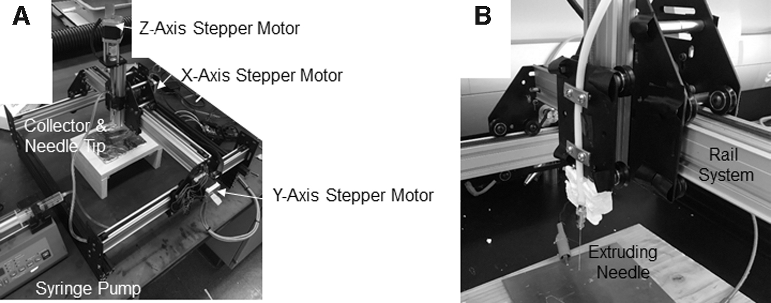
Representative image of our customized 3D printing electrospinning apparatus
Scaffold characterization
Topological characterization of all scaffolds was completed using Image J (National Institutes of Health [NIH]) analysis of microscopy images collected from all produced scaffolds. A minimum of five independent scaffolds were documented with a minimum of three to four locations per scaffold recorded. Scaffold fiber diameter was measured directly from calibrated images for front-facing fibers (only). Scaffold porosity was measured by converting images to binary data sets with manual thresholding. Manual thresholding was verified for independence and for retention of as much of the fiber characteristics as possible. The percent of void area was calculated directly from these binary images. 8 The percent void was calculated as the binarized black area divided by the total area of the picture for at least three independent scaffold formulations. We additionally attempted to collect data from the core of formed scaffolds and the periphery of formed scaffolds, to determine whether there are differences in scaffold characteristics as a function of deposition location throughout the scaffold.
Scaffold degradation was tested in culture media over the course of 48 h, to quantify the stability of formed scaffolds over the cell culture duration. In all instances, there were no significant differences in scaffold mass before placing the scaffolds in culture media and after the 48 h period (with a 24 h drying period). Thus, there was no need to normalize data by changes in scaffold mass.
In addition, the accuracy of the printed scaffold was compared with the coded dimensions used to control the movement of the extruding nozzle. Coded circular structures have a single unique value for diameter. Printed electrospun scaffolds, however, have a line-width. Thus, the average inner diameter (calculated from 8 measurements, each ∼45° apart) and the average outer diameter (calculated from 8 measurements, each ∼45° apart) were used to calculate a single independent average diameter of the printed scaffold. The average percent error between the single independent average diameter of the printed scaffold and the coded circular diameter was calculated and reported.
Cell culture
Human umbilical vein endothelial cells (HUVECs) were cultured with fabricated scaffolds to determine its use in biomedical applications. HUVECs were cultured as previously reported, 8 with the following modifications. HUVECs were purchased from ScienCell Research Labs (Carlsbad, CA) and cultured using conditions as outlined by the manufacturer (Dulbecco's modified Eagle's medium supplemented with 5% fetal bovine serum, 1% endothelial cell growth supplement, 0.5 U/mL penicillin, and 0.5 μg/mL streptomycin; all from ScienCell). Cell media were exchanged the day after seeding and then every other day thereafter. Cells were maintained as 37°C and 5% CO2 on flasks pre-coated with collagen.
HUVECs were passaged to cell culture plastic or scaffolds via trypsin digestion for no more than 3 min (at 37°C). Digestion was confirmed with light microscopy. HUVECs were cultured on scaffolds for 48 h to determine whether or not the scaffolds can support cell survivability. A live/dead cell cytotoxicity assay (consisting of 2 μM calcein and 4 μM ethidium) was added to the cells and scaffold for ∼5 min at 37°C. Stained cells were then imaged immediately under fluorescent microscopy to document and quantify the percent of cells that were alive (viability) and the cell density throughout scaffolds. Cell density provides us with a measure of proliferation as the seeding density before experiments was maintained at 1000 cells/cm2.
Statistics
All data were compared for significance using SAS (v9.4). Averages of independent scaffold physical property data were compared directly from recordings and assumed to be normally distributed. Biological property data were normalized by either the total number of cells present (cell viability) or the initial cell seeding density (proliferation) to provide us with a relative measure that can be compared. All data were analyzed for significance using ANOVA as a comparison between the quantified properties of the three individual scaffolds. Duncan's multiple-range post hoc test was used to examine for differences between pre-planned comparisons with an α set to 0.05. This work is exempt from IRB or IACUC review as this work did not include human data or animal experiments.
Results
Scaffold characterization
To determine whether or not electrospun scaffolds can be fabricated in a prescribed pattern using 3D printing techniques, we fabricated scaffolds using processing parameters in the same range and then compared the formed scaffolds. A conventional electrospun PCL scaffold, a 3D printed PCL scaffold, and a 3D printed electrospun scaffold (Supplementary Video S1, illustrates a representative print from our described method), formed using the processing parameters described earlier, were fabricated and imaged for characterization (Fig. 2). This figure illustrates that by using conventional electrospinning, scaffolds can be formed with randomly oriented fibers (Fig. 2A). Further, by using 3D bioprinting, we can fabricate highly organized scaffolds (Fig. 2B). By using the method described here, we can fabricate scaffolds that have a prescribed pattern (illustrated as a circle in Fig. 2C) that can be described by a random fiber deposition (Fig. 2D).

Representative microscopy images of electrospun PCL
Fiber diameter (Fig. 3A) and overall scaffold porosity (Fig. 3B) are important physical properties to quantify when developing scaffolds for potential use in biomedical applications. The average fiber diameter for the scaffolds prepared using the different fabrication techniques was significantly different from the average fiber diameter of scaffolds prepared with the other techniques (p < 0.0001). Conventional electrospinning prepared the largest fibers with the smallest diameter, whereas 3D printing prepared the largest fibers that were limited by the resolution of the needle gauge attached to our extruder. The 3D printed electrospun scaffold produced fibers that closely resembled that of the conventional electrospun scaffold technique, as this technique is not limited by the printing resolution. Further, the porosity of all scaffolds was analyzed and it was observed that the porosity of the formed scaffolds was independent of the fabrication technique.
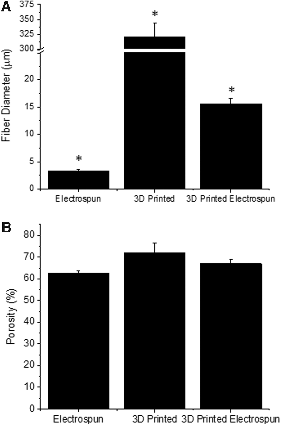
Average fiber diameter
We aimed at developing a method that allows for the formation of electrospun scaffolds with well-defined macrostructures, in addition to the regular microstructures provided by the electrospun scaffolds. To accomplish this, we compared the dimensions of the formed scaffold (representative scaffold shown in Fig. 2C) with the dimensions used to control the movement of the motors. The average line-width of printed scaffolds was 1.34 ± 0.2 cm, with an average inner diameter of 9.4 ± 0.4 cm and an average outer diameter of 11.7 ± 0.3 cm (all values are reported as the mean ± standard deviation). These values resulted in an average percent error of 5.5%, as related to the set dimensions for the printer.
Cell properties
HUVECs were cultured on all scaffolds as a means to determine whether or not the scaffolds could be used to support biomedical applications. After the 48 h culture duration, cell viability (Fig. 4A) and cell proliferation (Fig. 4B) were quantified. Cell viability was high throughout all scaffolds and was independent of the scaffold fabrication techniques employed. Cell viability on the 3D printed electrospun scaffold was in the range of typical electrospun and 3D printed scaffolds.
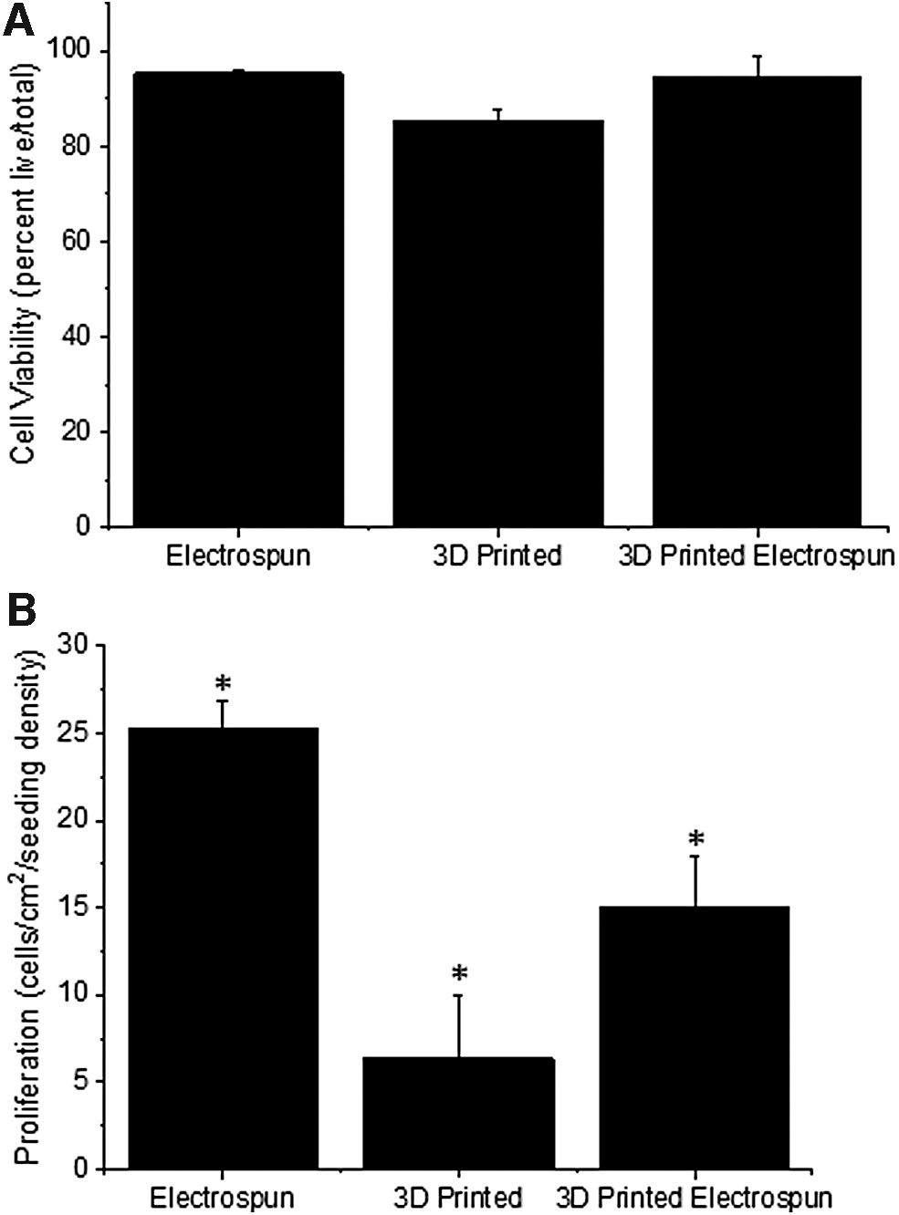
HUVEC viability
Cell proliferation throughout scaffolds was also quantified as a means to determine whether or not cells were both viable and able to grow during the culture duration (Fig. 4B). We observed different proliferation rates throughout the scaffolds for each of the fabrication techniques as compared with the other fabrication techniques (p < 0.0001). Scaffolds produced with conventional electrospinning techniques supported the highest endothelial proliferation rates over 48 h, whereas scaffolds produced with 3D printing techniques supported the lowest endothelial proliferation rates.
We also attempted to identify scaffold physical parameters that can be used to predict endothelial cell growth throughout the formed scaffolds. We found a particularly strong correlation between fiber diameter and the viability of HUVECs throughout scaffolds (Fig. 5A). Second, the scaffold porosity had a strong correlation with the proliferation of HUVECs throughout scaffolds (Fig. 5B). The correlation coefficient for each of the plots shown in Figure 5 was >0.99, illustrating that there is a strong relationship between the fiber diameter and the viability of cells throughout the scaffold and separately the porosity and the proliferation of cells throughout the scaffold. We observed that with an increasing fiber diameter there was a corresponding decrease in cell viability. Similarly, with an increasing porosity, there was a decrease in the proliferation rate of cells throughout the scaffolds.
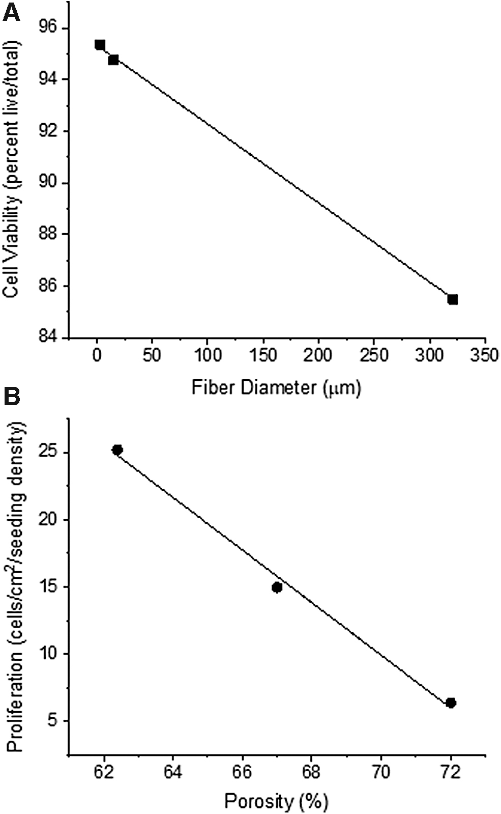
Correlation between scaffold fiber diameter and cell viability
Discussion
The primary goal of this project was to develop a method to combine 3D printing and electrospinning technology to develop porous fibrous scaffolds in a predetermined arbitrary pattern and to determine whether or not scaffolds produced with this technique have the potential to be used for biomedical applications. To accomplish this goal, we first had to identify parameters such that during the fabrication of conventional electrospun scaffolds the deposition spot size of fibers was relatively small. This was achieved by minimizing the distance between the needle tip and the grounded collector. The minimum distance that the collector tip was able to come within the grounded collector was 3 cm—the distance could not be further minimized without compromising the quality of the scaffolds. Our minimized distance was in the range of a previous report that moved the collector in an electrospinning apparatus, 24 instead of the needle as reported here.
Our 3 cm distance was then used to design our 3D printing electrospinning machine, as illustrated in Figure 1. To the best of our knowledge, this is the first reported system that has been designed to control the deposition of electrospun scaffold fibers in prescribed patterns, while retaining the random orientation of fibers within a prescribed geometry (Fig. 1). There have been reports that aimed at controlling the deposition of electrospun scaffold fibers; however, these reports aimed at producing scaffolds that resembled 3D printed layer-by-layer architectures that have proven to be ineffective in promoting cell growth into prescribed structures.24–26 Others have shown some improvement in these layer-by-layer approaches, but a global approach that combines the strengths of 3D printing and electrospinning has not been achieved by others. 20
There have also been reports illustrating the ability to control the position of the electrospinning extruder; however, these systems formed scaffolds that resembled conventional electrospun scaffolds and further the biological relevance of these scaffolds was not evaluated. 23 Our goal was to produce arbitrary patterned electrospun scaffolds that retain the random fiber deposition within the patterned structure. The system that was fabricated and reported here (Supplementary Video S1) can be scaled up for mass production of tailored 3D printed electrospun scaffolds as demanded by the particular application.
To compare the physical properties of our formed 3D printed electrospun scaffolds with conventional electrospinning and 3D printing, we fabricated scaffolds with similar processing parameters (Fig. 2). It should be noted that electrospun scaffolds were formed with typical gross morphologies, as many other groups have shown when electrospinning scaffolds.27,28 Similarly, the 3D printed PCL scaffolds that we produced have predefined morphologies based on our processing parameters and we choose to fabricate scaffolds in a linearly array of fibers, limited to the resolution of our printer. The 3D printed PCL and electrospun PCL have been shown to be viable candidates for various biomedical applications, including cartilage tissue engineering, 29 bone tissue engineering, 30 cardiac repair, 31 wound healing, 32 and vascular tissue engineering. 33 Thus, we choose to make use of PCL as our base polymer for 3D printed electrospun scaffolds. Further, the scaffold fabricated by combining 3D bioprinting and electrospinning has both a prescribed pattern (Fig. 2C) and a random deposition of porous fibers (Fig. 2D).
We characterized the fiber diameter and porosity of formed scaffolds as a means to quantify whether the newly formed 3D printed electrospun scaffolds have physical properties in the range of conventional scaffolds (Fig. 3). The fiber diameter of scaffolds varied somewhat significantly between our three fabrication techniques.
Interestingly, the 3D printed electrospun scaffolds more closely resembled the electrospun scaffolds in fiber diameter, as the overall fiber fabrication technique mimics that of electrospinning. Although the distance between the collector and the needle tip was matched between the 3D printed electrospun and electrospun scaffolds, there was a significant difference in fiber diameter. This may be attributed to the motion of the needle, which may have disrupted the Taylor Cone formation and overall time for the fibers to deposit. Note that the conventional 3D printed scaffolds fiber diameter is limited by the resolution of the printer and thus the formed fibers were somewhat larger than those produced by other methods.
Overall, the fiber diameter of the scaffolds that we produced with electrospinning was in the range of the fiber diameters produced in previous work from our lab, which focused on vascular tissue engineering and the work of others.8,9,34 It should be noted that the fiber diameter of electrospun scaffolds is a variable of many processing parameters (including flow rate, polymer viscosity, and voltage gradient) and it is, therefore, rare to have exact matches in scaffold fiber diameter for scaffolds produced from different methods.
The porosity of electrospun scaffolds is typically high and this allows cell growth throughout scaffold fibers, proliferation, and nutrient delivery. All scaffolds that were produced here had a high porosity that supported cell growth (Fig. 3B) and this is in agreement with the porosity of other scaffolds produced for tissue engineering applications. 35 Thus, our new method did not compromise the formed scaffold topological characteristics that were quantified here.
Further, the ability of our method to replicate random geometries was accurate with an overall percent error of 5.5%. The difference in set value for the print and the actual print is likely due to the electrospinning process, whereby fibers follow an expanding circular pathway from the tip of the Taylor cone to the collector plate. It is possible that the printing accuracy can be improved by altering the electrospinning processing parameters, such as distance between the extruding needle and the collector or the voltage gradient; however, this is not something that we attempted to optimize during this study.
To characterize the biological performance of scaffolds for potential biomedical application, we quantified the cell viability and proliferation of endothelial cells cultured on scaffolds for 48 h (Fig. 4). We observed a high cell viability after 48 h and a relatively high proliferation rate for all scaffolds. Interestingly, scaffolds that were produced with conventional electrospinning techniques had a significantly improved proliferation, as compared with 3D printed scaffolds, and this is likely due to the intrinsic nature of these scaffolds in resembling the innate vascular extracellular matrix in multiple physical properties and the larger thickness of these scaffolds in three dimensions. The cell culture parameters throughout our scaffolds (3D printed electrospun) were high and resembled those of conventional electrospinning.
We believe that this result was found since the topological properties of the 3D printed electrospun scaffold most closely resembled that of the conventional electrospun scaffold. In addition, this enhanced thickness would provide an overall larger area/volume for cells to grow throughout. Although most groups do not quantify proliferation as a function of scaffold area/volume, the viability and proliferation of cells throughout our scaffolds is in agreement with previous reports. This suggests that this new scaffold fabrication method can be used to produce scaffolds that are viable for biomedical applications.34,36
One of the most critical aspects of scaffold development is the ability to predict cell growth properties throughout the scaffold a priori. This has proven challenging, but interestingly we show a correlation between fiber diameter and endothelial cell viability, for scaffolds produced from PCL (Fig. 5A). Similarly, there was a strong correlation between scaffold porosity and endothelial cell proliferation throughout these scaffolds (Fig. 5B). Although this correlation may be limited to the particular conditions that we investigated here, it is important to note that with this information, investigators may be able to design scaffolds with specific growth attributes.
Conclusions
Overall, the goal of this work was to develop a method where electrospun scaffolds can be produced with well-defined geometrical constraints. We aimed at retaining the random orientation, fiber characteristics, and scaffold characteristics that are associated with electrospinning and at the same time illustrate that these 3D printed electrospun scaffolds can be used for biomedical applications.
Herein, we report a method to 3D print electrospun scaffolds. Our method was able to produce scaffolds that retain the macro-geometric features as determined by the 3D printing component and the micro-architecture determined by the electrospinning process. Further, our scaffolds were fabricated from a polymer commonly used for biomedical applications and were able to support the growth of endothelial cells in culture. This suggests that this method can be used for vascular applications and broadened to other biomedical applications. Importantly, we were able to identify correlations between scaffold properties and cell culture parameters, which may be a valuable predictive tool when designing and developing scaffolds for use in biomedical applications.
Footnotes
Acknowledgments
The authors would like to thank the Department of Biomedical Engineering at Stony Brook University for supporting this work through the Senior Design (BME 440/441) process. Dr. Wei Yin provided invaluable insight into the design and development of this device as the instructor of BME 440/441. The authors would also like to thank Bonnie Macaluso, Steven Ghitis, and Eva Gallegos for their valuable technical support during the work described herein.
Authors' Contributions
All authors meet the definition of authorship as: substantial contributions to the conception or design of the work; or the acquisition, analysis, or interpretation of data for the work; drafting the work or revising it critically for important intellectual content; final approval of the version to be published; and agree to be accountable for all aspects of the work in ensuring that questions related to the accuracy or integrity of any part of the work are appropriately investigated and resolved,
Author Disclosure Statement
No competing financial interests exist.
Funding Information
No external grant was used to support this work. The Department of Biomedical Engineering at Stony Brook University supported the purchase of some components required for this work.
References
Supplementary Material
Please find the following supplemental material available below.
For Open Access articles published under a Creative Commons License, all supplemental material carries the same license as the article it is associated with.
For non-Open Access articles published, all supplemental material carries a non-exclusive license, and permission requests for re-use of supplemental material or any part of supplemental material shall be sent directly to the copyright owner as specified in the copyright notice associated with the article.