
Abstract
Based on the established system of concrete-filled fiber-reinforced polymer (FRP) tube (CFFT) in civil engineering and construction industry, this research presents a novel fabrication method for freeform FRP formwork through an additive process of winding FRP fabric with industrial robots. Different from the filament winding or fused deposition modeling process in additive manufacture, large-scale formwork is fabricated with layered winding of FRP fabric and simultaneously applying fast cure epoxy resin in the proposed methods. It increases the fabrication speed and material efficiency compared with the typical fabrication process of FRP formworks, and achieved the geometry flexibility from the numerically controlled additive process. The fabrication methods are developed through a series of preliminary tests, exploring the appropriate fabrication parameters, such as the overlapping height of each layer, winding speed, and epoxy resin type. Two additional prototypes addressing geometrical flexibility are also fabricated. Based on the feasibility studies, the article discussed the potential application of this system on a double-skin tubular arch (DSTA) bridge and a tree-like topological optimized column as the future outlook of this method. As developed based on the established construction systems such as CFFTs and DSTAs, not only the proposed system is compatible with current structure and construction system, but it also benefits from combining an off-shelf material with a flexible and accurate programmable robotic process. This research contributes to the scope of additive manufacturing system by targeting the fabrication of nonuniform optimized large-scale structures.

Introduction
With the development in structural design and topology optimization, 1 there is an increasing need to fabricate the customizable large-scale structural components with nonstandard geometry, while the fabrication process of these structures in a rapid and cost-efficient manner remains a challenge. The application of concrete structure components with nonuniform sections in construction is restricted by its steep cost, mainly due to the extra cost and time on the customized formwork. 2
The development in additive manufacture (AM, also known as three-dimensional [3D] printing) makes mass customized concrete structures possible without extra formwork.3,4 Although a variety of AM technologies are developed for small-scale rapid prototyping, the majority of large-scale AM for building industry is based on 3D concrete printing (3DCP). However, as the material composition of 3DCP is different from the conventional concrete, for example, more additives and no coarse aggregates in the 3DCP, and the challenge to integrate it with typical connection and reinforcement system, there are significant challenges to incorporate the 3DCP into the established construction process, thus restricting the wide application of AM to on-site constructions. 5
This article proposes a fabrication system for nonstandard curve-shaped formwork for concrete casting using a novel AM method. This new fabrication method was inspired by the concept of the fiber-reinforced polymer (FRP)-confined concrete structure,6,7 in which the tubular FRP structure serves both as stay-in-place formwork and as confinement for the concrete inside. Using the FRP tubes as the concrete formwork also saves the falsework, which significantly reduces the interruption of traffic and the on-site construction waste. In previous applications, the FRP tubes are usually prefabricated using filament winding or wet layup method based on standard base formworks, while in this research, industrial robot and AM method is used for the fabrication of FRP tube with customizable geometry. It explores the potential of utilizing industrial robotic systems for on-site fabrication of optimized structural members with higher geometrical flexibility and material efficiency, while significantly reducing the transportation cost and the subsequent energy consumption.
The main advantages and innovation of this new fabrication method are as follows:
The shape of the fabricated tube is numerically controlled by the robotic arm with high accuracy, allowing the components to be fabricated with curvature and nonuniform sections, without significantly increasing the cost and time. The fabrication method is proposed to be applied on the FRP-confined concrete structures, which provides a feasible industrial application for it and increases the compatibility of the fabricated component with an established construction system. The formwork fabricated serves both as the stay-in-place formwork and as confinement for the concrete, which reduces the construction waste and increases the concrete material efficiency, meanwhile the FRP layer can also protect the concrete inside from the corrosion environment. FRP fabric, instead of FRP filament, is used for the tube in the proposed method. It helps increase the fabrication speed by covering larger areas with the same winding runs compared with filament winding or fused deposition modeling (FDM). With the application of industrial robot, the current system can accommodate components up to 2.2 m tall, and expandable with additional external linear axis, making its application in the fabrication of the large-scale structural components possible. The proposed fabrication process can be conducted on-site where the robots are accessible, which can significantly reduce the transportation cost of prefabricated formworks.
This article presents a novel fabrication method for FRP tubular sections as the concrete formwork using fabric winding by robotic arms (Fig. 1). The fabrication process is first presented, then three prototypes with different geometries are fabricated, followed by the application outlook of this fabrication concept. This application broadens the boundary of AM, and provides an efficient and automatic way of fabricating large-scale formwork for the FRP-confined concrete structures.
Concrete formwork fabricated with robotic FRP winding. FRP, fiber-reinforced polymer.
Background and Relevant Projects
FRP-confined concrete structures
FRP has been widely applied on the reinforcement of existing structures, by externally binding the FRP laminates on the structure surfaces.8–10 More recently, concrete-filled FRP tubes (CFFTs) have also been developed, in which the tubular FRP profiles are used as the stay-in-place formwork for concrete filling,11–13 as shown in Figure 2. In CFFTs, the FRP section confines the concrete core and acts as structural reinforcement, when loaded, the concrete is acting under a three-axial compression load, and the FRP laminate is under tensile load so that both materials can be efficiently utilized. The FRP tube also acts as a durable and corrosion-resistant protector for the concrete core, which makes this type of structure ideal for the bridge piers, marine piers, and girders.14,15
Left: cross-section of CFFT; middle: cross-section of DSTA; right: a 12.5 m span DSTA bridge. CFFT, concrete-filled FRP tube; DSTA, double-skin tubular arch.
A 12.5 m span bridge system based on the CFFT called the hybrid double-skin tubular arch (DSTA) bridge was developed in the University of Queensland (Fig. 2). 13 In DSTA section, an additional steel tube is used inside the FRP tube, so the concrete is confined by the outside FRP skin and the inside steel skin, much higher load carrying capacity can be achieved than the CFFTs without significant self-weight increase. 13 Currently, the construction process of the DSTA bridge is divided into five main steps: (1) fabricate the FRP and steel tube segments and transport to the factory construction site, (2) put the steel and FRP tubular segments in position in the factory, (3) weld the steel sections and connect the FRP segments by FRP wrapping, (4) concrete casting and hardening, and (5) transport the bridge to the construction site and install the bridge. In step (1), the FRP tubes were fabricated overseas, and it was time- and cost consuming to transport them to the factory in Australia; and in step (5), significant extra cost is needed for transportation and traffic control to transport the whole bridge to the construction site.
Fabrication methods for FRP tubes
In CFFTs and DSTAs, tubular FRP sections are used as the formwork and confinement for the concrete inside. Filament winding, wet layup, and pultrusion are the most commonly used methods for FRP tubular section manufacture. A wide range of sections, such as circular section, rectangular section, and elliptical section, can be manufactured using these methods.12,13,16 Filament winding is currently the most commonly used method for the FRP tube in the CFFT and DSTA sections; it creates tubular composite sections by winding the filament under tension over a rotating mandrel.17–19 Fiber strength can be effectively utilized by carefully designing the fiber layouts in filament winding method, and various sections and sizes can also be fabricated; however, its application on concave sections is very limited. A project called BUGA Fiber Pavilion 2019 20 tried to solve this problem by exploring a coreless filament winding method, which winds the FRP filaments between two rotating winding scaffolds, and builds the predefined concave shapes from the interaction of the filaments. Wet layup method, or the so-called hand layup method, puts layers of FRP fabrics into or against the mold, and shapes the sections by the resin applied between the layers; both concave and convex sections can be manufactured using this method.21,22 Wet layup method is also widely applied for the repair or reinforcement of concrete structures by externally wrapping the FRP mat on the beam or columns, which can effectively enhance the mechanical behavior of the reinforced structure.23,24 Pultrusion is a highly industrialized method for FRP sections; the resin-saturated FRP fiber is first guided and hardened to the designed shape in a heated steel-forming die, and then the profile is pulled out and trimmed into the desired length.25,26 Limited by the pultrusion process, fiber in the section is always parallel to the section length, while in the FRP-confined concrete structures the FRP fiber should be orientated along the hoop direction to provide confinement for the concrete. Thus, pultrusion is not suitable for the FRP-confined concrete.
The above-mentioned traditional fabrication methods for FRP profiles are usually well suited for factory production, but not for on-site application owing to the limitations of the accessibility to highly controlled manufacture facilities. Also applying the current industrial prefabricated FRP profiles on-site demands additional cost in storage and transportation.
Topology optimization
Recent studies on topology optimization have found that material efficiency can be significantly improved by using irregular sections to replace the conventional sections in the design of structural members. 27 Within the last decade, a dynamic approach using the finite element analysis has been developed for structural optimization. This technique seeks the most efficient way of using the material by altering the shape, topology, and geometry of the buildings and its structural components. 28 The optimized structures are usually featured with changing cross-sections along the member span or height, such as the tree-like structure exhibited at 2019 IASS Form and Force Expo. 29 The proposed fabrication method has a strong outlook in fabricating large-scale topologically optimized structure.
Additive manufacturing method for concrete formwork
AM30,31 method makes it possible to fabricate the topology optimized structures in an accurate manner. AM represents the process of fabricating 3D objects by adding layer-by-layer material; materials commonly used for AM including plastic, 32 metal, 33 and concrete.4,34,35 Traditionally, AM is mostly applied for fabricating the solid components defined by computer, so that optimized, nonstandard, and esthetic construction components or even structures can be manufactured without using extra formwork, and meanwhile the construction waste can be significantly reduced.4,35,36 However, the application of the AM technology on building-scale structures is still limited by some factors, such as the steep cost of printing large components and the difficulty of integrating the AM components with steel reinforcement.2,37,38
Recent trials of using AM for fabricating the concrete formwork or tubular sections provide a way to solve these problems. Kayser et al. 39 in Massachusetts Institute of Technology proposed a multirobot system called “FIBERBOTS” to manufacture a series of large-scale FRP tubular structures. In this project, a fleet of robots worked parallel from the ground up to enable collaborative and site-specific construction of the tube structures using fiber winding. Peters 40 in Kent State University investigated a method of fabricating the formwork for concrete casting using FDM, while they found that it is challenging to apply this method on structural scale due to the concrete hydrostatic pressure. “Eggshell” developed in ETH Zurich 41 proposed a fabrication process for large-scale tubular formwork using robotic FDM and can simultaneously cast the concrete inside. Eggshell solved the problem of concrete hydrostatic pressure, while the formwork fabricated only works as concrete formwork without increasing the concrete material efficiency, which can be further optimized. Another project called “Mesh Mould” in ETH Zurich 42 explores a robotic fabrication process for the nonstandard curved reinforcement, which also acts as the formwork for the concrete. Besides, a range of research studies on dynamic form casting have been conducted through dynamic fabrication with a numerically controlled formwork, achieving a balance between shape customization and fabrication efficiency.43,44
Method and System Design
In this project, the glass fiber-reinforced polymer (GFRP) fabric is winded over a designed path by the robotic arm, and then hardened by the resin applied on it. GFRP fabric was chosen as the material in this system because it is flexible when no resin is applied, so it can easily be fabricated to curved shapes with the guide of the robotic arm; and when the resin applied is hardened, it will hold its shape and provide high confinement to the concrete inside because of its high strength. A workflow is carefully designed to control the moving path of the arm and guide the GFRP fabrics to fabricate the designated form. The additive fabrication system starts from the bottom of the structure, where an initial section with GFRP fabric is fabricated on a short tubular base, and the section height is extended by winding fabric layers over the lower fabricated part. Resin is applied alongside the winding process, and the speed is carefully calibrated to ensure that the lower layers of the extruded fabric would be hardened enough to hold its shape while the top layers are still malleable to be shaped by the position roller. The moving path and speed of the robotic arm are investigated so the shape of the fabricated structure can be accurately controlled. Because of the high flexibility of the FRP fabric, the fabricated tube can change its shape and direction progressively as the winding process develops (Fig. 3). After one segment is finished, the fabricated formwork will be removed from the base before mounting into place for concrete casting. The fabrication process of the proposed method is as illustrated in Figure 4.

Design and fabrication workflow of the proposed method.
End-effector
An end-effector is designed to guide the fabric winding and carry the GFRP fabric roll (Fig. 5). Three passive rollers are designed in the end-effector, including one position roller (Fig. 5E) and two supporting rollers (Fig. 5F). While winding, the free end of the GFRP is first attached to the fabricated tube, then set between the position roller (Fig. 5E) and supporting roller (Fig. 5F.a), followed by attaching to the other supporting roller (Fig. 5F.b), and finally connected to the GFRP roll (Fig. 5H). In this preliminary design, the size of the end-effector is designed to carry a 150 mm wide, 50 m long GFRP fabric roll, which is enough to fabricate an 800 mm tall tube with an average diameter of 250 mm.

Design of the end-effector and path planning.
The position roller (Fig. 5F.a) sits inside the fabricated profile to ensure the accurate position of the fabricated section. The supporting rollers are designed to hold and ensure the GFRP fabric is driven in tension. A spring damper is connected to the supporting roller (Fig. 5F.a) to apply pressure on the newly winded fabric, so it can be fully appended to the previous winded layers. Another spring damper is connected to supporting roller (Fig. 5F.b) to tighten the fabric. The current end-effector requires a minimum 120 mm clearance on the inner side of the tube to operate, which restricts the minimum diameter of the fabricated tube to be 120 mm. In the original design, there was a resin dispersing mechanism (Fig. 5C) designed in the end-effector beside the position roller and supporting roller (Fig. 5F.a). However, owing to the difficulties in balancing the curing time and dispersing speed of the resin, in the preliminary explorations, the resin is applied on the fabricated tube by brush manually.
Robot settings
The head of the end-effector (Fig. 5I) was connected to the Kuka KR16 robot arm to drive the GFRP fabric. During the fabrication process, the end-effector operated in a spiral path around the fabricated tube; therefore, the sixth axis was set on a limitless mood in the robotic arm. The data configuration file was set, so the robotic arm can rotate beyond the default ±360° in a limitless spindle mode. The path planning of the robotic arm was generated by the KUKA|prc 45 and the Grasshopper plugin 46 of the 3D modeling software Rhino 3D. 47
Material Properties
The section is composed of woven FRP fabric and epoxy resin. The FRP fabric used in the prototype was plain-woven GFRP fabric with a 150 mm width and 155 gsm density. The adhesive used in the prototype was a two-part epoxy resin Ampreg 22 with fast hardener; the mix ratio of the resin and hardener was 100:28 by weight. The prototype was fabricated at the indoor environment with a temperature of 25–30°C. A 100 g resin was used in each mix, and the pot life (working time) was ∼15 min before the viscosity of the mix was too large to be applied by brush. The tensile strength of the cured epoxy resin is 70.3 MPa according to the supplier. 48
Prototype Fabrications
To validate the feasibility of the proposed method, three prototypes have been fabricated with it. An FRP hollow segment with a height of 800 mm and cross-section changing from a circular base with a 250 mm diameter to an elliptical top with 280 and 180 mm axial lengths is first fabricated to validate the proposed fabrication concept (Fig. 1). Following the success of the initial prototype, a complementary experiment was carried out by fabricating two additional prototypes, validating the capability of such system in fabricating formworks with more flexible geometries such as changing section and developing along a curved path.
Prototype A: a straight hollow section
A straight hollow section with a height of 800 mm and cross-section changing from a circular base with a 250 mm diameter to an elliptical top with 280 and 180 mm axial lengths was first fabricated. The prototype tube was fabricated with the following workflow (as shown in Fig. 6). Before the fabrication, one end of the FRP fabric was fixed to the circular cardboard base at three points using paper fasteners. Then, the first layer of GFRP fabric was applied over the base following the guide of the robotic arm. Right after the fabric layer was applied, the mixed adhesive was applied by brush on the outer surface of the tube. Then, the second fiber layer was applied on top of the first one, with an overlap of 140 mm (i.e., section height increases 10 mm after each layer), and then resin was applied again. Each mix of 128 g resin was enough for five layers of fabric, then the manufacturing process was paused for 30 min for the resin to be hardened. Afterward, the GFRP fabric was winded directly over the hardened GFRP tube, and then repeated the process until the full height is finished.

Fabrication time-lapse photographs of Prototype A.
Three failed experiments were conducted before the first success prototype was built (Fig. 7 and Table 1). The following technical skills were concluded from the trial tests in Prototype A to provide a reliable fabrication quality:
Left: samples of success and failure version of testing prototypes; right: the inner surface of a successful prototype.
Summary of the Four Tests for Prototype A
These values are theoretical numbers.
(a) Proper hardener should be used in the fabrication. In Test 1, slow cure hardener was used, the fabrication process stopped after ∼1 h because it took only a few minutes to wind the first few fabric layers while taking >1 h for the resin to cure. In Tests 2–4, fast cure hardener was used instead.
(b) The overlapping height of fabric layers is essential for the success of the fabrication process. When the overlapping height is small, the section height increases fast after each spiral run; however, the section may not be strong enough to hold the later layers. To reduce the GFRP material usage and increase the fabrication speed, 100 and 120 mm overlaps between two adjacent GFRP layers (which means the section height increased 50 and 30 mm with each spiral run) were used in Tests 2 and 3. But the resultant section stiffness was not enough to maintain the section shape when applying the upper layers. In Test 4, an overlap of 140 mm between adjacent layers was found to provide enough stiffness for the tube to hold its shape, so the tube height increased 10 mm with each spiral run and there were 15 layers of fabric in each standard tube section.
(c) The winding speed of each spiral run was controlled to be 1 min for the robotic arm and 2 min for resin application. After each resin mix (five layers of fabric), the process should be on hold for 30 min for the resin to be hardened. As a result, the inner layers supporting the bottom part of newly winded fabric should be cured for ∼45 min, so it is hard enough to keep its shape during the passive winding of FRP fabric; and the outer layers of the wrapped fabric should be cured for ∼30 min to ensure it is malleable and can be adapted to the section change during the fabrication process.
(d) Excessive resin should be avoided at the outer surface of the tube, so the supporting roller inside the tube (Fig. 5F.a) is clean from the resin. As the resin creates adhesive force between the roller and the fabric during the rolling process, if excessive resin permeate through the fabric layers, the inner layers of fabric will stick to the position roller, when the position roller move forward, the fabric will move with it and the shape of the fabricated tube will be changed. (Fig. 7, Tests 2 and 3). To avoid this undesired deformation, the top freshly winded 3–5 cm of GFRP fabric should be kept clean from resin when applying the adhesive.
(e) At the end of the fabrication, there was a 150 mm high region with decreasing layers because of the winding process, as shown in Figure 8. This part is thinner than the rest of the formwork, when assembling the segments in the structure, it will be further reinforced by manual GFRP wrapping, which also connects adjacent segments.

The section of FRP formwork and its condition during the winding process.
Evaluation
To evaluate the fabrication quality, a circular tube with 200 mm diameter was fabricated using the proposed fabrication method. The tube was scanned to check the fabrication accuracy compared with the designed shape, and then split tests were carried out to check the tensile strength of the tubes in hoop direction. The scan results are as shown in Figure 9; a 150 mm tall part in the middle of the tube was taken to check the geometry accuracy. It shows that the average deviation of the tube was 3.57 mm, while the overall shape accuracy was 98.4%. Split tests were carried out according to ASTM D2290, 49 5 standard rings (with 15 layers of fiber) with 29.92 mm average height and 4.32 mm average thickness were cut from the tube for the tests. The average tensile strength of the rings was 52.32 MPa.

Fabrication accuracy from scan data.
Local bump (delamination between layers) was observed in the tube, especially within the layers beside the inner surface, as shown in Figure 10. As discussed in the previous part, exclusive adhesive was avoided to reduce the undesired deformation caused by the adhesive force between the supporting roller and the fabric. This also makes most part of the inner fabric layers clear from resin (Fig. 8), so with low interlayer bonding in this part. Besides, when we look close into the fabricated surface, inclined pattern can be observed (Fig. 6), this was caused by the traction force of the fabric while winding.
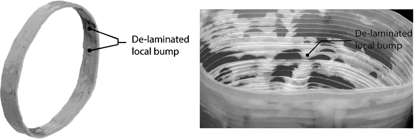
Local bump within the inner layers. Left: scan data; right: photograph.
Prototypes B and C: tubes with nonstandard sections and varying direction
After achieving the first successful prototype using the proposed fabrication method, two more prototypes as shown in Figure 11 were fabricated following the same process. Prototype B is a 500 mm high tube with a circular base with 200 mm diameter and varies to be a shamrock-shaped section at the top, while Prototype C is a circular hollow section changing its direction gradually during the fabrication process. These two prototypes further showcased the feasibility of using this fabrication method on GFRP hollow sections as nonstandard concrete formwork.
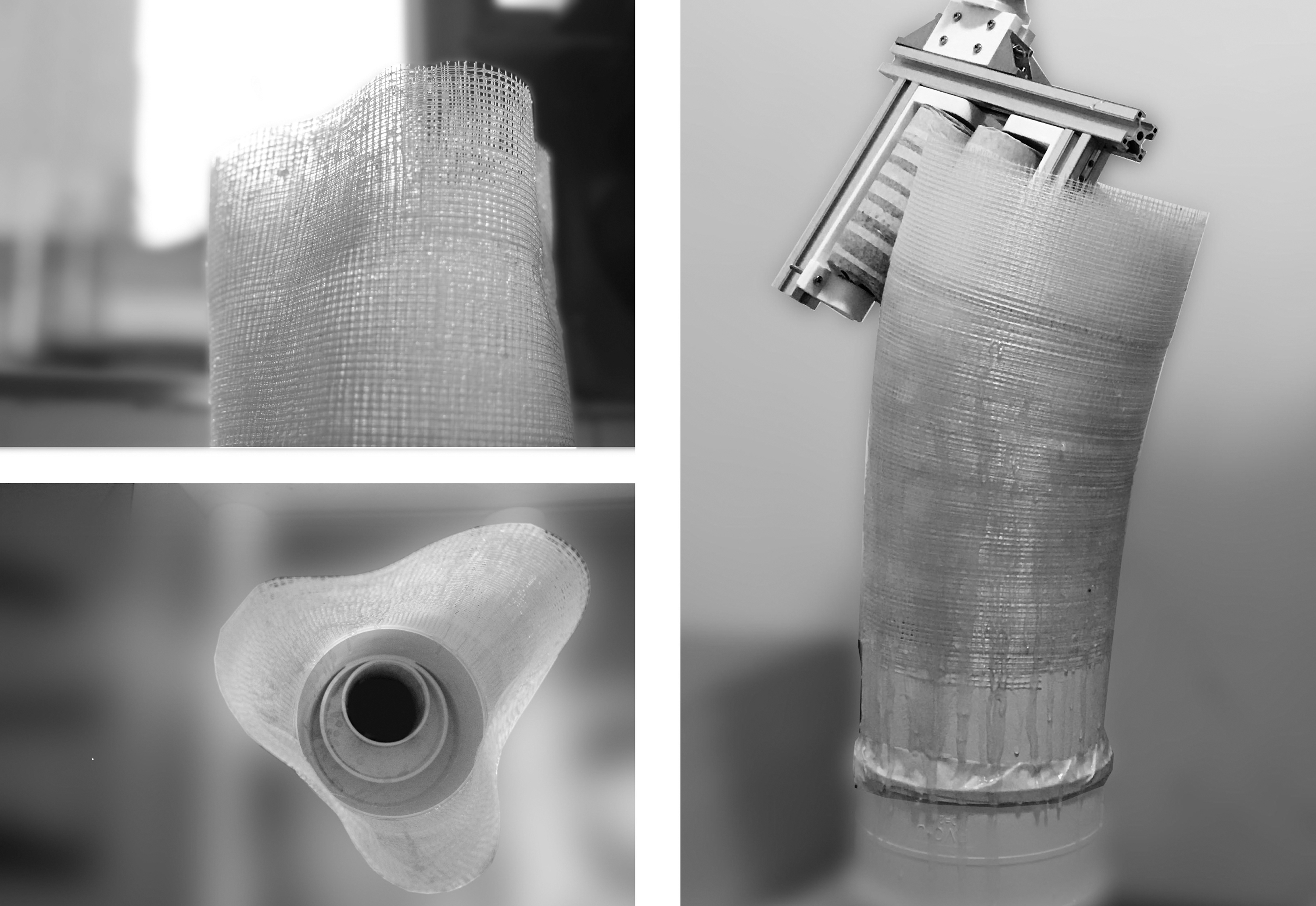
Left: Prototype B, a tube with nonuniform section; right: Prototype C, a tube with changing direction.
Discussion
The average fabrication speed of the current prototypes was 100 mm/h (height increase). There are several possible ways to speed up the winding process. For example, fabric with higher stiffness can be used to reduce the required overlapping layers for each section and larger height increase with each winding; and the general-purpose epoxy resin can be replaced by ultraviolet-curing resin to accelerate the curing process. These aspects will be studied in future research.
The concrete confinement in the CFFTs is mostly provided by the FRP strength in the hoop direction. 50 In this study, the split test results showed the high strength of the fabricated tube in hoop direction, which verifies the potential of applying it in the CFFTs. In addition, the impregnation of the resin at the outer surface layers helps holding the concrete in the tube. Traditionally, in the FRP mat-reinforced concrete structures, the mat is wrapped on the concrete surface by wet layup method, while in this application the fabric is winded in a loose aggregation. Whether the confinement provided by the FRP formwork in this study is comparable with the traditional FRP confinement is yet to be evaluated.
Outlook of this Application
This article explores the integration of emerging technologies in digital structural design, AM technique, and established structure systems, including topological optimization, robotic fabrication, and FRP reinforcements. In this research, three prototypes have been developed with a novel fabrication method based on a synthesis of the technologies to fabricate the highly optimized nonstandard structures in a cost-, time-, and material-efficient way.
This fabrication method was inspired by the CFFT or DSTA structures in which the FRP tube works as the formwork and confinement for the concrete inside. Based on the established construction sequence of CFFT or DSTA structure, which includes prefabrication of circular steel core and FRP skin/formwork, FRP formwork trimming, installation, and segment jointing with wrapping, 13 an application outlook of the proposed method is presented in this part on the in situ construction of a topologically optimized and customized large-scale structure with FRP with similar construction sequence.
Applying bidirectional evolutionary structural optimization (BESO) 51 algorithm on the loading condition and design domains in Figure 12, an optimized tree-branch-like structure is generated. To fabricate the BESO-generated structure, the generated geometry is first preprocessed and refined to be compatible with the proposed fabrication system. The workflow is composed of the following steps:
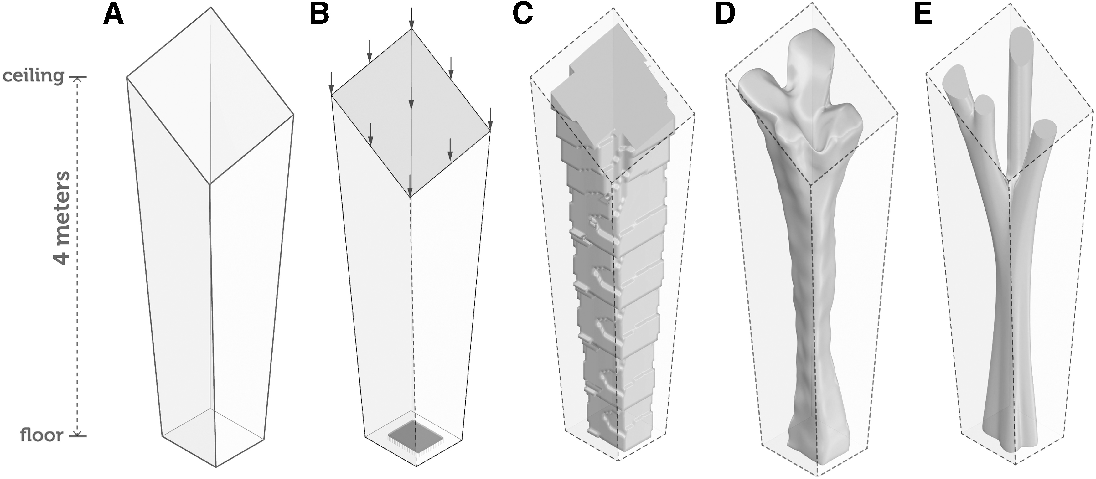
Structural column topological optimization process:
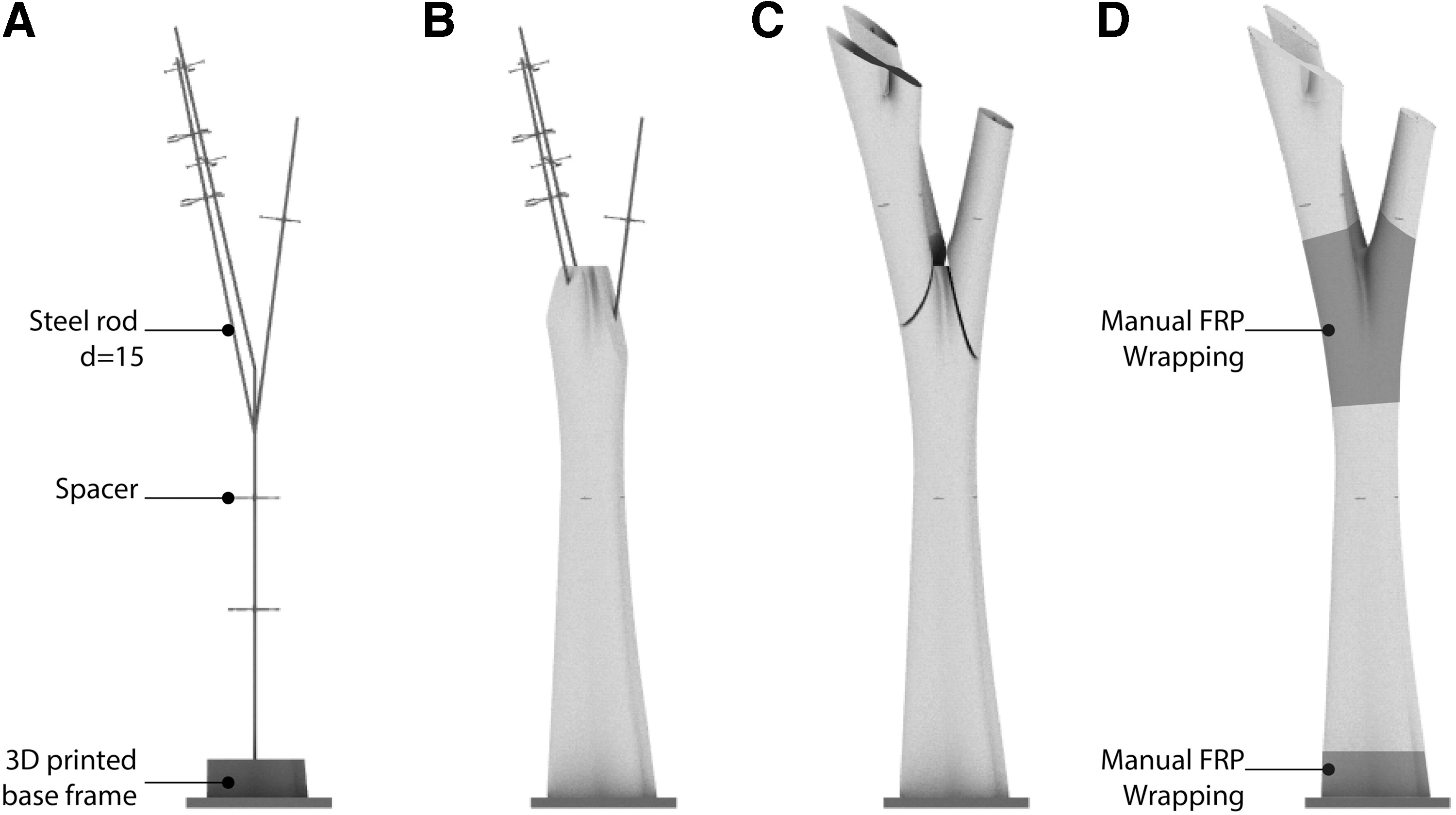
(a) Segmentation of geometry. The structure is divided into segments to fit the operation range of the robot and the compatibility of the fabrication process. The geometry is usually separated at the branching root since the current system does not accommodate the fabrication of branching geometry (Fig. 13A, B). Meanwhile, a steel core is extracted from the geometry as the skeleton.
(b) Geometry preparation. The geometry of each segment is processed by computer to extend the end-surface to be in a full loop of the tubular geometry (Fig. 13C). The geometry is also adjusted to ensure the clearance and gradient are compatible with the end-effecter.
(c) Prefabrication of steel core. The prefabricated steel core is made of standard steel profiles such as channel, angle, or steel rod; the skeleton is prefabricated as standard segments and will be assembled with the FRP formwork fabricated on-site.
(d) FRP formwork winding. The outer surface of each segment of the optimized column is fabricated on-site with the system developed in this research using FRP winding, starting from a short 3D printed base with the same geometry of the end or branching root region of the optimized geometry (Fig. 13D). After the formwork is finished, it will be removed from the base, and the extra part at the ends will be trimmed according to the geometry of the original segment (Fig. 13E).
(e) Steel core and formwork installation. The steel core will be placed at the base (Fig. 14A), followed by the “trunk” part of the column, which will be fabricated outside of the steel core using the proposed winding method (Fig. 14B). Then, the fabricated “branch” formwork will be placed at the designed location of the skeleton and be joined with other segments by a manual FRP wrap around the joints (Fig. 14C, D). After the FRP parts are finished, the concrete can be cast in the tube.
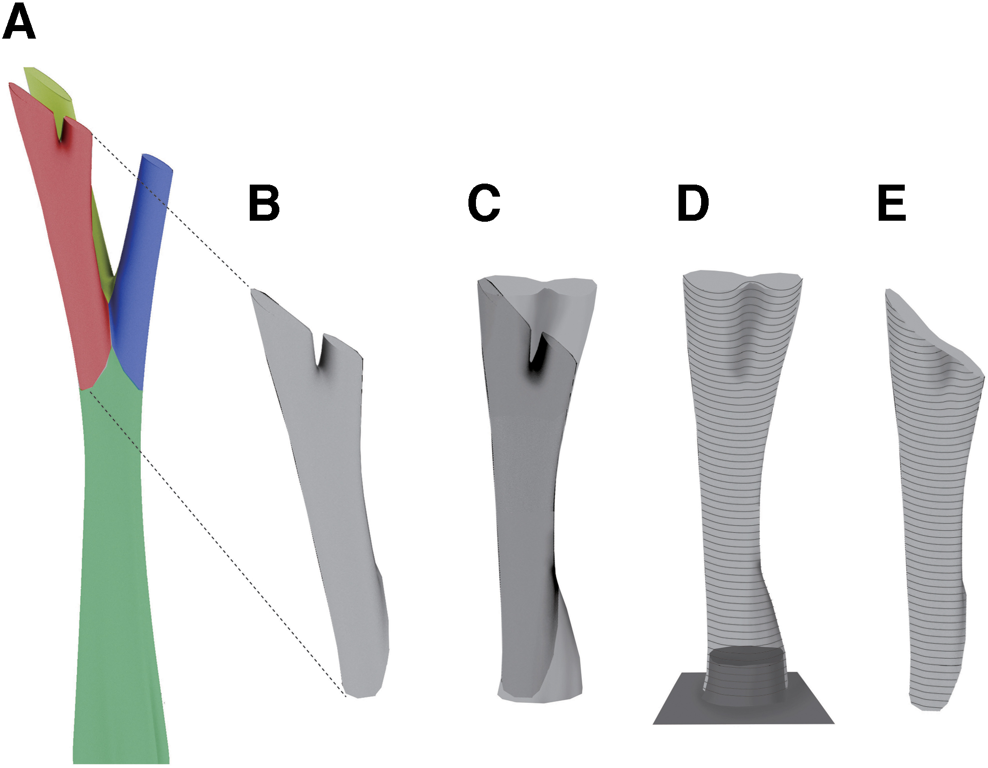
Processing and fabrication process of a segment of the column:
Assembly sequence:
This study is a preliminary research on the feasibility of this fabrication method, while more work is needed to upscale this method in the upcoming research. For example, more systematic studies will be done to check the relationship between the overlapping height, fabrication speed, and overall strength for different section sizes and shapes; concrete will be filled inside the tube, and the compressive strength of the confined concrete will be compared with the plain concrete; epoxy resin dispenser and the dispense rate will also be studied for a better automatic and accurate control.
Conclusion
As demonstrated and verified with the fabricated prototype, this article presents a new fabrication method for the customizable FRP tubular structure, which can be used as both the concrete formwork and the structural reinforcement for large-scale nonstandard sections. The nonuniform structural formwork is manufactured by robotic winding of GFRP fabric; fast cure adhesive resin is applied during the winding process so the fabricated tube can be self-supported. Multiple layers of fabric are winded in a spiral way to extend the segment with changing section and direction using the path planning of industrial robots. The proposed system makes it possible to fabricate large-scale customized tubular formwork on-site, where the robots are accessible, and then concrete can be cast. The unparalleled flexibility in the system made the fabrication of highly optimized structure system possible without a significant increase in cost and construction waste. Although the proposed method has only been applied on indoor condition, it has high potential to be applied on-site, as the fabrication process is highly robotic controlled, which guarantees the fabrication quality in different environments.
The method and prototypes developed in this research provide an alternative solution to fabricating customizable large-scale structural members for on-site construction. The system is derived from a well-developed construction process, allowing it to be compatible with existing building process in the construction industry. With the rapid fabrication of customizable FRP formwork, the novel method can significantly reduce the cost of transportation and possible damage of the tubes, while increasing structural flexibility and efficiency.
Footnotes
Author Disclosure Statement
On behalf of all authors, the corresponding author states that there is no conflict of interest.
Funding Information
The authors received financial support provided by University of Queensland and the Science and Technology Innovation Program of Hunan Province (Grant No. 2020RC4049).