




Abstract
In selective laser sintering (SLS), process parameters are essential to fabricate outstanding mechanical properties products. In this research, process parameters of porous Polyamide 12 (PA12) scaffold were investigated for the sake of obtaining superior mechanical properties. The area energy density (AED) determined by laser power, scanning speed, and scanning space was employed as the main index to assess process parameters. Six groups with different AED were planed, and then cubic and cylindrical samples were modeled and fabricated with PA12 powders via SLS. Afterward, mechanical properties of the samples were measured and studied to achieve optimum parameters. After a detailed comparison of micrograph, density, dimensional accuracy, and mechanical properties of samples under different AED, laser power of 16 W, scanning speed of 2500 m/s, and scanning space of 0.12 mm were found to be the optimum parameters. Further, a 60% uniform porosity scaffold was fabricated with the optimum parameters to measure mechanical properties for evaluating the optimized results, which were elastic modulus of 87.79 MPa, yield strength of 8.25 MPa, and Poisson's ratio of 0.3. Finite element simulation was also performed, and the results exhibited a good agreement with the experimental behaviors.
Introduction
Selective Laser Sintering (SLS), one of the additive manufacturing techniques, is a rapid prototyping technology developed in recent years that selectively fuses powders to build parts layer by layer. 1 The SLS is widely used in bone tissue engineering to fabricate complex geometric scaffolds with different porosity due to its wide range of materials and higher parts quality.2,3 Polyamide 12 (PA12) is the most widely material used in laser sintering because of its easier processability by SLS and relatively low cost compared with the other available material. 4 Therefore, SLS with PA12 powders is extensively applied to fabricate scaffolds in bone tissue engineering. 5 The process parameters such as laser power, scanning speed, scanning space, layer thickness, and preheating temperature affect the resulting quality of the SLS-fabricated scaffolds directly. 6
Research that discussed the effect of process parameters on the parts quality has been carried out.7–9 Craft et al. reported the influence of extend sintering times on the mechanical behavior of PA12 parts by powder bed fusion generated with three different processes. 10 Stichel et al. back traced the pore morphology to the process parameters via analyzing pore morphology measured by X-ray computed tomography, and they observed that pore density is strongly affected by the process temperature. 11 Singh et al. investigated the effects of process parameters on the part density and hardness. 12 Tan et al. studied the relationship among energy density and the Young's modulus, ultimate strength and dimensional deviation of the sintered parts. 13 Besides, finite element simulation was also employed to provide guidance for process and efficiency prediction to obtain optimal process parameters.14,15
The SLS provides powerful capacity to fabricate complex geometric parts with tailored porosity, which satisfies the porous requirements of tissue engineering scaffolds. 16 Therefore, the influence of SLS process parameters on the porosity and mechanical property of the produced scaffolds is another important aspect that should be considered.17,18 Tan et al. evaluated the microstructural of the scaffolds produced by SLS using electron microscopy that the result ascertained the potential of SLS-fabricated tissue engineering scaffolds. 19 Liu et al. proposed an SLS fabrication process of bone scaffold with titanium biomedical materials. 20 Tortorici et al. investigated the relationship between the process parameters (laser power, beam compensation, and beam diameters) and dimensional accuracy of the sintered scaffolds to produce highly porous scaffold. 21 Chiu et al. studied the SLS process of bio-glass scaffolds with the iron element, and it was successfully manufactured at a certain energy density. 22
Although experiments studying the influence of process parameters on the quality of sintered parts have been conducted, research on the process parameters of tissue engineering scaffolds has been still limited. With the purpose of obtaining the optimum process parameters of PA12 powders applied to tissue engineering scaffolds as accurately as possible, the present research employs the area energy density (AED) controlled by the layer power, scanning speed, and scanning space to evaluate the effects on the sintered PA12 parts quality through experimental methods. Parameters such as layer thickness and preheating temperature were also taken into account. A scaffold was produced in the optimized parameters, and finite element simulation was also performed to evaluate the results.
Materials and Methods
Wavier statement
Now the study is in the process research stage, and it has not been applied to clinical treatment. Therefore, all experiments in this paper do not involve human or animal subjects, and this behavior also do not violate ethics.
Material properties of PA12 powders
The materials used in experiments were spherical PA12 powders purchased from Evonik specialty chemicals (Shanghai) Ltd. The Quanta FEG 250 SEM was used to investigate the microstructures of the powders. Figure 1a shows the micrograph of PA12 powders previously treated by spray-gold. It was found that the PA12 particles were ellipsoids with different sizes. Figure 1b illustrates the diameter distribution of PA12 particles by using QICPIC/L02-OM dynamic image analyser. Frequency distribution characterizes the ratio of the particles number within current size range to total particles. Cumulative distribution is defined as the ratio of the particles number under a certain size to total particles. The average particle diameter of 56.08 μm and main distribution range of 36.48–70.57 μm (D10–D90) were, respectively, obtained from the diameter distribution.

SEM morphology and particle-size distribution of PA12 powders.
Differential scanning calorimetry (DSC) analysis was used to determine the temperature-dependent material properties of PA12 powders from solid to liquid phase. The STA 449F3 comprehensive thermal analysis instrument was employed to perform DSC analysis for tracking the melting behavior of the powders, as shown in Figure 2. It was observed that the melting point of the PA12 powders is 178°C according to the extended lines interaction.

The DSC and TG curves of PA12 powders. The blue triangle representing the melting point of PA12 is the intersection of two extended lines. DSC, differential scanning calorimetry.
Experimental approaches
Preheating temperature and layer thickness in process parameters can be optimized through single factor experiments, but laser power, scanning speed, and scanning space are hard to gain ideal results by the same method. Therefore, the AED is used to describe the interaction of the three parameters:
where AED is the area energy density, p is the laser power, v is the scanning speed, and h is the scanning space.
The melting point of PA12 powders was considered to determine the preheating temperature of 170°C, and the layer thickness of 0.1 mm was obtained from our previous work. 23 The experiment cases with different parameters listed in Table 1 were carried out to produce real test samples. The SLS machine used in experiments was HW-S4040 produced by Wuhan 3DPAction Technology Co, Ltd. Figure 3 illustrates the shape of samples designed according to GB-T1041–92. The cube with the size of 10.4 × 10.4 × 30 mm was used to analyze dimensional accuracy, density, and fracture morphology, and the cylinder with the size of φ12 × 30 mm was employed to analyze cylindricity and compressibility. The six groups of experiments were divided into two parts, that one to three groups and four to six groups were, respectively, formed at one time via the SLS process.

Test samples designed according to GB-T1041–92.
Experiment Cases with Different Process Parameters
AED, area energy density.
Scaffold design and simulation procedure
To evaluate the optimized results, a scaffold was fabricated with the optimized process parameters as described in the Micrograph, Density, Dimensional Accuracy, and Mechanical Properties of Samples section via SLS and the compressive mechanical properties of the scaffold were tested. The scaffold was designed as a uniform porosity structure, of which volume fraction was set as 60% with 5 × 5 × 5 unit cells in a cubic space of 24 × 24 × 24 mm and the cell size was set as 2.7 × 2.7 × 2.7 mm, as shown in Figure 4.

The uniform scaffold fabricated with the laser power of 16 W, scanning speed of 2500 mm/s, and scanning distance of 0.12 mm.
For the sake of obtaining the compressive mechanical properties of the scaffold, a mechanical compressive test was performed by using an electronic universal testing machine of WDW-100. The compressive displacement was applied with 1 mm/min loading rate, and thus force-displacement data were generated. To prevent anisotropic effects, the loading direction was the same with the printing direction. Meanwhile, the 3D finite element analysis was carried out in an ideal condition by using ABAQUS/CAE to compare the numerical and experimental stress–strain results. Compressive displacement was applied to the 3D model, and the results of simulation were compared with the stress–strain rates from the experimental test. Properties of the material used in the simulation were modeled with Young's modulus of 87.79 MPa, yield strength of 8.25 MPa, and Poisson's ratio of 0.3 (seen in the Simulation Results and Validation section).
Result and Discussion
Micrograph, density, dimensional accuracy, and mechanical properties of samples
The micrographs of cubic samples were obtained through JEOL JSM-7800F scanning electron microscopy, as shown in Figure 5. It was observed from Figure 5a and b that there was an obvious phenomenon that insufficient sintering between layers with AED <0.05 J/mm2. It was seen from the fracture surface that there were clear boundaries in layer by layer that resulted from an incomplete melting of particles. When AED was added up to 0.05 J/mm2, the fracture micrograph showed a rough surface with some holes in Figure 5c and f, in which the boundaries among layers disappeared completely. The fracture surfaces in Figure 5d and e were improved into smooth surfaces with no voids when AED went up to 0.07 and 0.06 J/mm2, respectively. It was seen that the surface quality of both figures did not exhibit obvious difference. It was shown that smooth surfaces with no holes could be obtained as AED exceeded 0.05 J/mm2 for PA12 powders.
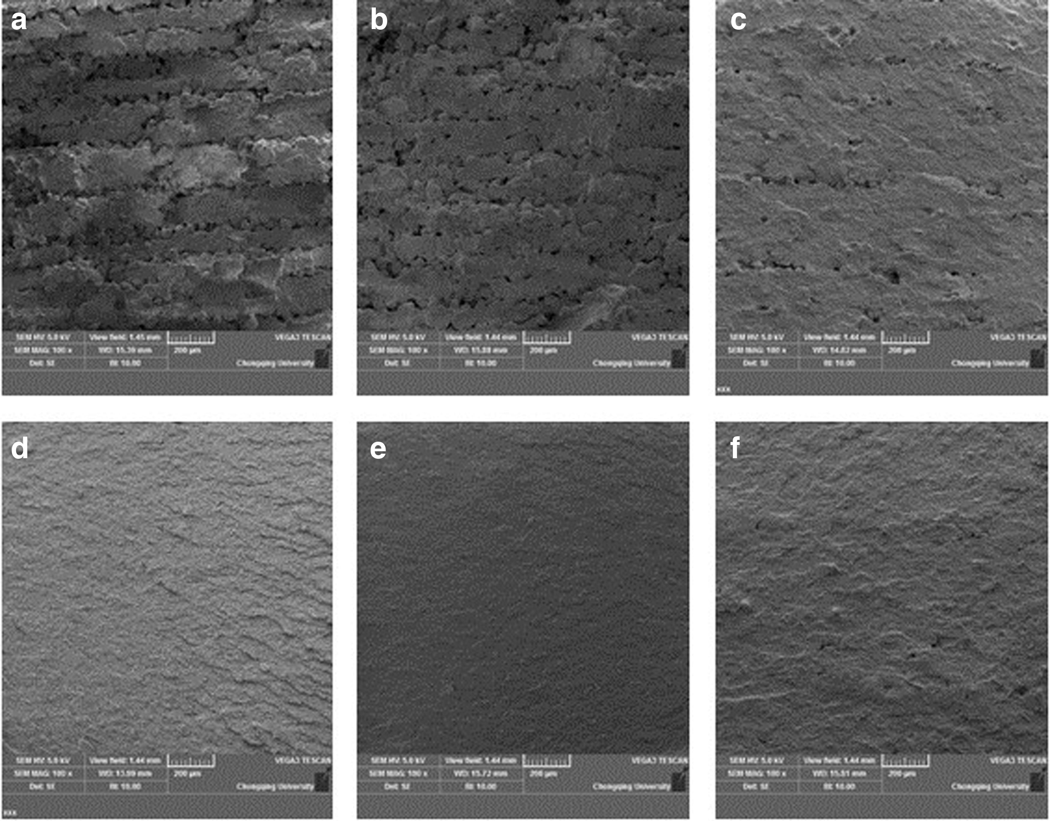
SEM images of the cubic sample's fracture surface of PA12 powders with different AED.
Density for the cubic samples was obtained through calculating the rate of the effective volume to surface volume, and the results are shown in Figure 6. It should be noted that as AED increased, the density for all cubic samples increased distinctly as the fluidity of melted powders was improved with the increase of temperature. A similar trend was also obtained for laser power while measuring the density of SLS samples. 12 Further, the fourth group with 0.07 J/mm2 was observed to be the maximum density of 0.91.

The effect of AED on density.
The dimension and cylindricity errors of cylindrical samples are illustrated in Figure 7a and b. The trend of dimension error in three directions was almost the same as that of AED, which was in agreement with the cylindricity results. It was observed that the dimensional errors of X and Y directions exhibited little difference but those of the Z direction were much larger as powders were sintered layer by layer in the X-Y plane whereas it was compacted by a roller in the Z direction. It was also found that the minimax error of dimension and cylindricity was obtained at AED of 0.07 J/mm2.
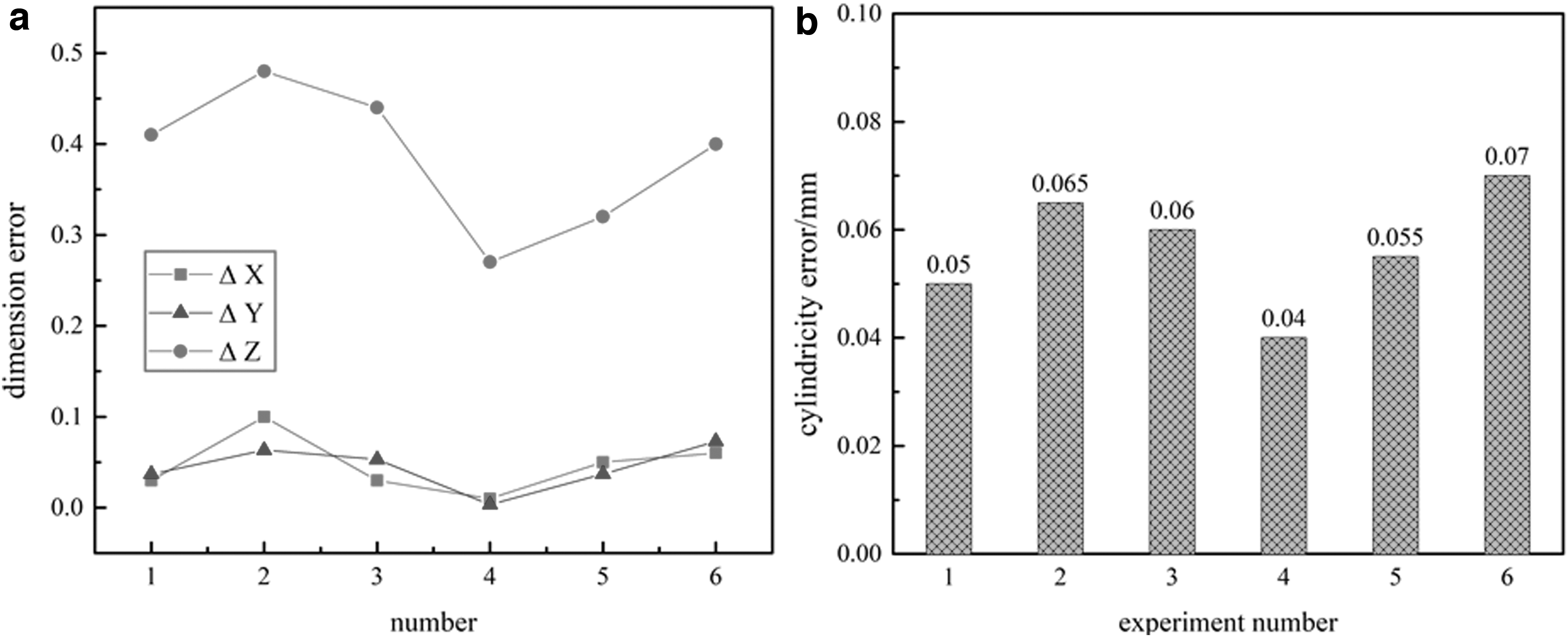
The effect of AED on dimensional accuracy.
Compressive tests were employed to analyze the stress–strain behavior of cylindrical samples. Figure 8 illustrates the compressive stress–strain curves of all cylindrical samples. The compressive yield strength and elastic modulus obtained from stress–strain curves are listed in Table 2. It was found that the fourth experiment with AED of 0.07 J/mm2 had superior mechanical properties, such as compressive yield strength of 42.18 MPa and elastic modulus of 1193.36 MPa. This resulted from the different density of cylindrical samples in which density had a direct bearing on the mechanical properties of samples.
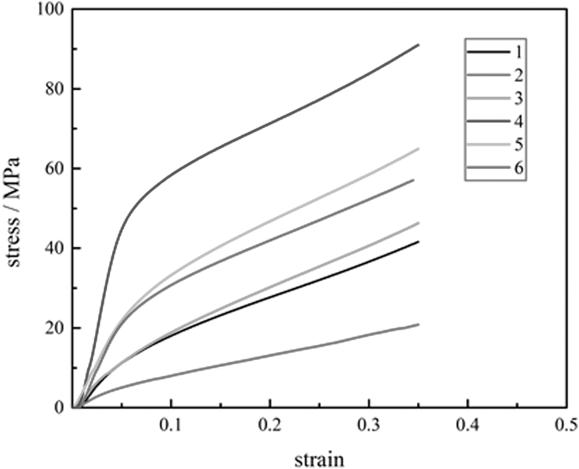
Experimental stress–strain curves of cylindrical samples.
Compressive Mechanical Properties of Cylindrical Samples
Considering the comprehensively aforementioned comparison of six groups in micrograph, density, dimensional accuracy, and mechanical properties, it was inferred that the optimal parameters were laser power of 16 W, scanning speed of 2500 m/s, and scanning space of 0.12 mm with AED of 0.07 J/mm2.
Simulation results and validation
According to research results, porous structure could enhance mechanical properties of scaffolds, which was a feasible method to avoid stress shielding between scaffolds and bones. 24 Figure 9 illustrates the stress–strain curves of the experiment and simulation. The scaffold was fabricated with a laser power of 16 W, scanning speed of 2500 m/s, and scanning space of 0.12 mm. The mechanical properties of the scaffold were elastic modulus of 87.79 MPa, yield strength of 8.25 MPa, and Poisson's ratio of 0.3 according to the experimental curve. The compressive yield strength of the porous scaffold in this article was 8.75 MPa, which was far greater than 0.56–3.71 MPa of the femoral neck.25,26 Therefore, the porous scaffold made of PA12 powder could provide sufficient compressive yield strength. Moreover, Singh et al. demonstrated superior biocompatibility of the PA-2200 scaffold through cultivating cells in the porous scaffold. 27 It shows the applied potential of PA12 in the bone tissue engineering scaffold.
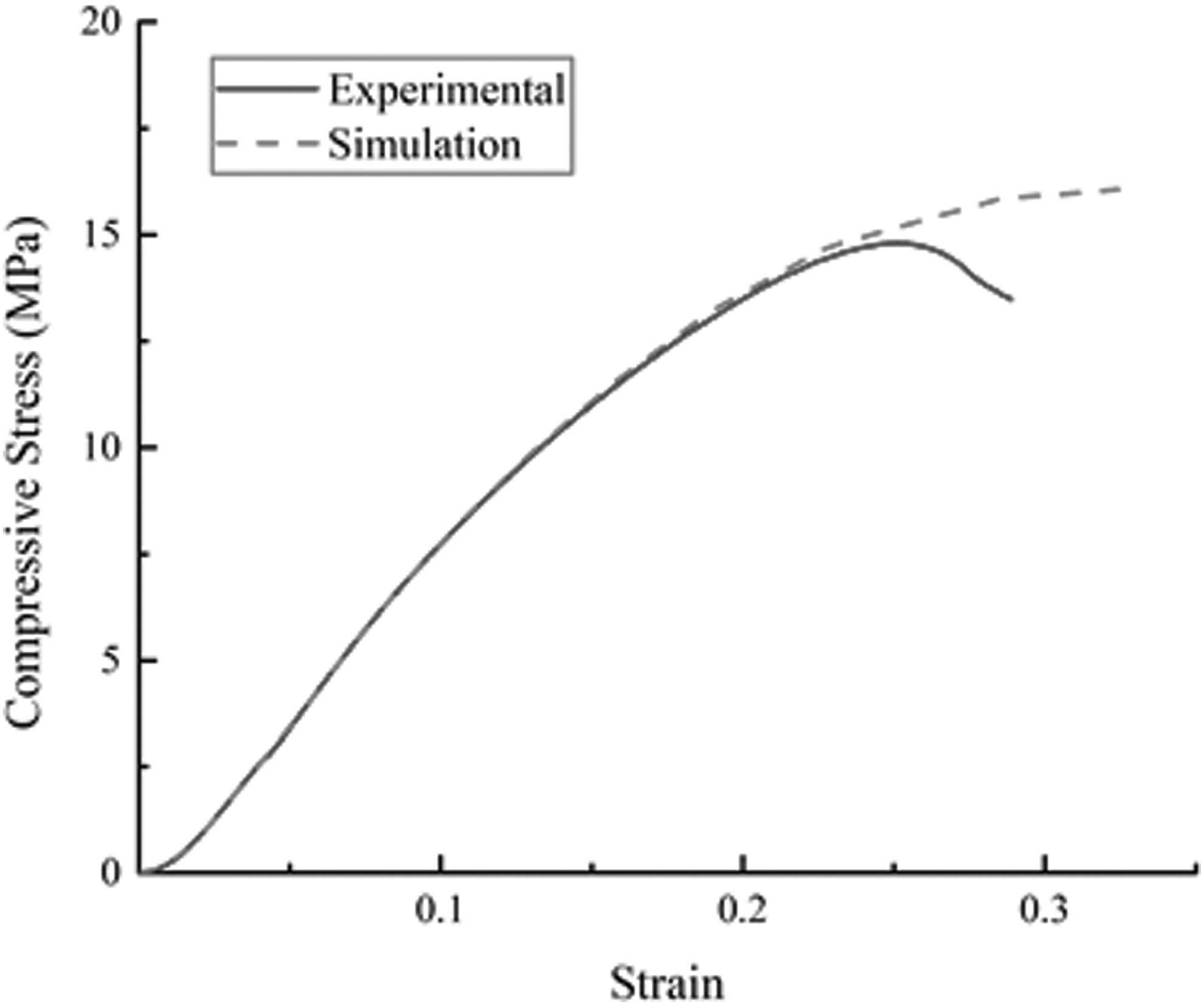
Comparison of simulated and experimental stress–strain curves.
Comparing the experimental and simulation results, it was also found that since a damage mechanism was not defined in simulation and the unit cells needed to be deleted that also existed in the model, the results of simulation overestimated the mechanical properties of the scaffold where stress release was observed in the experimental results. 28 The stress–strain curves indicated good agreement between simulation and the experiment.
Figure 10 illustrates the stress distribution and plastic strain deformation pattern of the 60% uniform scaffold at different strains. It was observed that the vertical struts of the uniform scaffold undertook much larger stress than the horizontal struts. Moreover, it was also found that stress concentration occurred in the first layer and the lowest layer of the structure. It was similar to the plastic deformation in the structure, and the stress and plastic strain distributions in each layer of the scaffold at different strains were almost consistent.

The simulation of stress distribution and deformation pattern.
Conclusions
For the sake of obtaining superior mechanical properties of the bone tissue engineering scaffold, experiments with different AED were carried out to investigate the influence of process parameters on the sintered quality. Six experiments with different AED were planned and then cubic and cylindrical samples were modeled and fabricated with PA12 powders via SLS. Micrograph, density, dimensional accuracy, and compressive mechanical properties of samples were taken into consideration to evaluate the sintered quality. It was observed that the sintered quality was improved with the increase of AED. The results suggested that the fourth experiment was superior to the others. Therefore, the optimal process parameters were laser power of 16 W, scanning speed of 2500 mm/s, and scanning space of 0.12 mm. Besides, the preheating temperature and layer thickness were set to 170°C and 0.1 mm, respectively.
To evaluate the optimized parameters, a scaffold with uniform volume fraction of 60% was fabricated in aforementioned parameters via SLS. A uniform scaffold was conducted under empirical tests as well as numerical studies were undertaken. Compressive tests were carried out, and finite element analysis was also performed. Mechanical properties of the scaffold fabricated with the optimized parameters were elastic modulus of 87.79 MPa, yield strength of 8.25 MPa, and Poisson's ratio of 0.3. The simulation of stress and strain distribution showed the situation of struts when the scaffold was subject to a load. The numerical and experimental stress–strain curves were compared, and it was observed that the results of finite element simulations have shown good agreement with the experimental behaviors.
Footnotes
Author Disclosure Statement
No competing financial interests exist.
Funding Information
This work was supported by the National Natural Science Foundation of China (Grant No. 51775069), Chongqing Science and Technology Commission (cstc2020jcyj-msxm1369, cstc2019jcyj-msxmX0362), and Chongqing Education Commission (KJQN201801118).