
Abstract
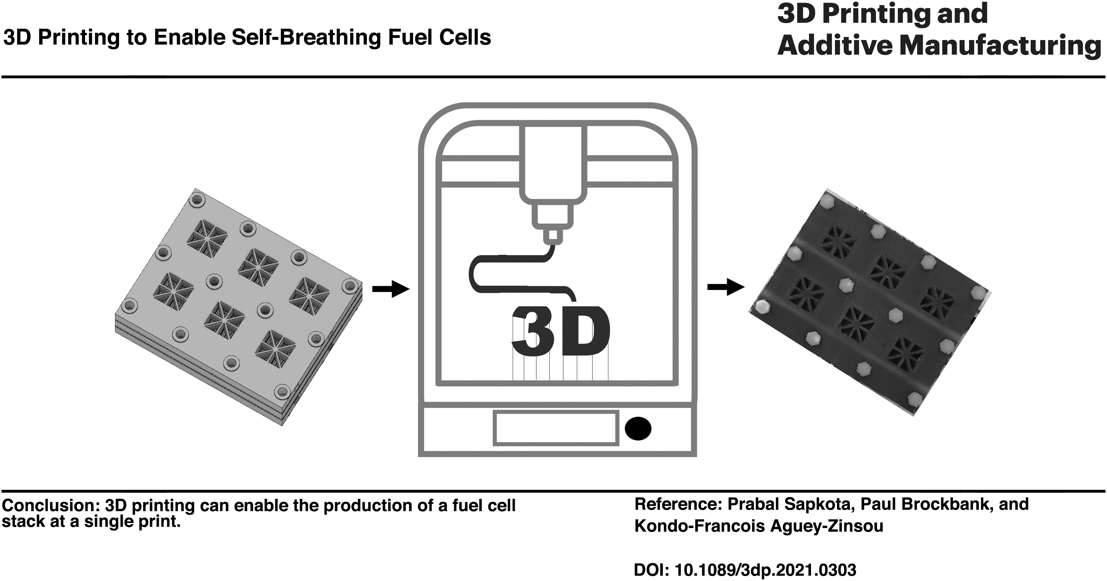
Fuel cells rely on an effective distribution of the reactant gases and removal of the byproduct, that is, water. In this context, bipolar plates are the critical component for the effective management of these fluids, as these dictate to some extent the overall performance of polymer electrolyte membrane fuel cells (PEMFCs). Better bipolar plates can lead to a significant reduction in size, cost, and weight of fuel cells. Herein, we report on the use of photoresin 3D printing to fabricate alternative bipolar plates for operating self-breathing fuel cell stacks. The resulting stack made of 12 self-breathing PEMFCs achieved a power density of 0.3 W/cm2 under ambient conditions (25°C and 20% relative humidity), which is superior to the performance of previously reported self-breathing cells. The problems associated with hydrogen leaks and water flooding could be resolved by taking advantage of 3D printing to precisely fabricate monoblock shapes. The approach of 3D printing reported in this study demonstrates a new path in fuel cell manufacturing for small and portable applications where an important reduction in size and cost is important.
Introduction
Polymer electrolyte membrane fuel cells (PEMFCs) are considered as a facilitator of clean energy systems as they convert hydrogen directly into electricity leaving only water as a byproduct. 1 PEMFCs are relatively simple systems in their concepts, but the widespread deployment of fuel cells relies on the development of novel approaches to enable a simplification in their design, allow ease in manufacturing, and thus applications beyond large-scale systems and automotive, especially at the mW to W scale to power small or portable applications.
In addition to problems associated with the storage and transport of hydrogen,2–4 several issues preclude the broad utilization of fuel cells. These include: (1) an excessive dependence on platinum (Pt) as a catalyst,5–8 (2) some level of inflexibility in the cell manufacturing, (3) heaviness and bulkiness of PEMFC stack, and (4) the reliance on secondary devices such as air blowers and humidifiers. In this context, the emergence of alternative bipolar plates is considered to be critical, because current bipolar plates hold 80% of total weight, 50% of total volume, and 40% of total cost of a fuel cell. 9 Bipolar plates are crucial to fuel cell operation, that is, fluid management, as they distribute the reacting gases, that is, H2 and O2/air, allow for the removal of the water produced, and collect the electrons from the membrane electrode assembly (MEA).1,9
In current bipolar plate design, various flow fields, such as pin, parallel, serpentine, and interdigitated, have been proposed for the efficient management of the fluids. The industry has in some cases adopted mixed flow field designs for better performance, for example, parallel/serpentine at the anode and pure parallel at the cathode. 10 Toyota has developed a 3D complex flow field for automotive applications. 11 However, complex design and cost-effective manufacturing processes are often not compatible. 10 In the case of miniature fuel cells, the use of parallel flow fields are a suitable approach, as these fuel cells do not require high pressure at the input to push H2 and O2/air along the flow fields and avoid water accumulation generated by the electrochemical reaction,10,12 or through back diffusion from the cathode especially at low current density (<0.2 A/cm2).13,14
Current bipolar plates are commercially made of graphite composites and metals. Graphite composites are based on a mixture of a polymer matrix (e.g., epoxy resin, phenol resin, polyethylene) with a carbon filler (e.g., graphite, carbon black). These enable flexibility in manufacturing, good corrosion resistance and low manufacturing cost.10,15–17 Alternatives are metal based, for example, aluminum, titanium, and zirconium bipolar plates.15,18 Metals have the advantage of good electrical and thermal conductivity, gas impermeability, and flexibility in machining. However, metals such as aluminum are highly corroded under fuel cell operation. Titanium and zirconium are corrosion resistant but expensive. Stainless steel, nickel, and aluminum alloys are low-cost alternatives.15,16,18
The common methods for manufacturing graphite composite-based bipolar plates are injection molding and compression molding. Hollow embossing, electromagnetic forming, and milling are used for metallic plates. Some of the emerging technologies are hydroforming and additive manufacturing (3D printing).1,19 Hydroforming is mainly used for metallic bipolar plates and has the advantage of enabling the making of complicated components with fewer operations, 20 whereas 3D printing can be used for both composites, metallic bipolar plates and photopolymer resins.21,22 In addition, 3D printing facilitates the use of simple and cost-effective printing machines, which can enable rapid prototyping without additional tooling cost.21,23
Some work has been previously reported on the development of bipolar plates for PEMFCs by using various 3D printing technologies, including direct metal laser sintering of titanium alloys, 24 selective laser sintering using graphite, 25 stereolithographic using clear resin, 26 and metallic printed plates based on nickel/chromium alloys. 27 Among these techniques, prototypes developed by stereolithography led to be best accuracy upon printing. 26 Through these technique flow fields, including serpentine, parallel, and 3D mesh of complex geometry, have been successfully printed,24,26,27 and operated at 60–75°C and 100% relative humidity (RH).24,25 Printing of other PEMFC components, such as gas diffusion layers (GDLs) 28 and catalyst layers, 29 have also been shown to be possible. However, the parts developed by 3D printing were found to usually lead to slightly lower performance (by 20%) in comparison to conventionally made PEMFC components, and this was mainly due to the nonuniformity of the 3D printed surfaces.24,29 Better stack performances were reported with printed complex 3D mesh flow field. 27
The use of 3D printing in electrochemical applications is relatively new; however, it can be expected that this technology could enable new avenues in PEMFCs' manufacturing beyond the existing traditional manufacturing methods of compression molding and stamping.1,30–32 Three-dimensional printing is a growing industry with an estimated revenue of $23 billion in 2019, 22 and the use of existing printable photopolymer resins could already enable a simplification in PEMFCs' manufacturing methods and new bipolar plate designs leading to superior PEMFC performances. Three-dimensionally printed photopolymer resins are softer (Youngs modulus up to 2.8 GPa) than steel (193 GPa), but harder than graphite composites (up to 60 MPa).33–35 However, resin-based printed parts have poor thermal conductivity (0.681 W/[m·K]) 36 in comparison to graphite (209 W/[m·K]) 37 and steel (16.3 W/[m·K]). This can be easily overcome by coating the printed bipolar plates with a conductive metallic layer. 38 A recent publication by Tarancón et al. highlighted the status and challenges of 3D printing in energy sector. 39
Herein, we report on a novel scalable approach for making self-breathing fuel cell stacks by using a 3D printing method to manufacture advanced bipolar plates from a photopolymer resin. Through this approach, a 12-celled stack was developed in a single anode plate and this provided means for effortless stacking of the self-breathing cells. The issue of gas sealing often encountered in self-breathing PEMFCs could then be simply resolved by using a silicon gasket, and high corrosion-resistant stainless steel could be used instead of gold-plated current collectors. To overcome the problem of water accumulation, a parallel flow field incorporating water reservoirs was implemented. This approach also maximized the utilization of H2.13,40 As per our knowledge, this is among the few instances a PEMFC stack has been fabricated using a 3D printer, as this demonstrates new avenues in the democratization of PEMFC stacks' design and making.
Experimental Section
Design of self-breathing PEMFC
The aim of this work was to develop a 1 W stack with design parameters listed in Table 1. To achieve this, a 3D model of a 12-celled self-breathing PEMFC stack was developed with Autodesk Fusion 360 (Fig. 1). The anode plate is composed of anode flow fields for six cells on each side of the plate. The two cathode plates have open slots to allow for the air breathing of the six cells. The following design parameters were calculated with the aim to achieve the required performances (Table 1).

3D model of the self-breathing PEMFC stack showing the two cathode end plates and the anode plate. PEMFC, polymer electrolyte membrane fuel cell.
Design Parameters
Design parameters
The amount of hydrogen to be supplied to the stack for a given power output can be calculated from
41
:
where Pe is the power generated by the stack and Vc is the operating voltage of an individual cell. For a stack to generate 1 W with each cell operating at 0.4 V, 19 mL/min of hydrogen should be supplied to the stack.
Similarly, the amount of O2 for a given power output is given by
41
:
and thus, for the stack to generate 1 W and each cell to operate at 0.4 V, O2 should be fed to the stack at 11 mL/min.
The amount of H2O generated by the stack is calculated from the equation below
41
:
Accordingly, the water produced during 1 W power generation at 0.4 V is 0.01 mL/min.
Finally, the heat generated by the stack (in terms of electrical power) can be calculated as
41
:
Hence at 1 W operation and 0.4 V per cell, the heat generated is equivalent to 2 W power.
Simulation of flows across the stack
The 12-celled stack and a single cell were simulated by computational fluid dynamics (CFD) with a fluent solver. The fluid flow was assumed to be a laminar flow due to low flow pressure and velocity gradient, 42 and the simulation was done at 25°C and 1 bar pressure. In the 12-celled stack, the movement of water from the anode chamber toward the reservoir (Fig. 1) was assumed to be gravity driven and the rate of the supplied hydrogen at the anode was 19 mL/min. In the case of a single cell, the PEM module in the fluent solver was used, where the H2 and O2 mass flow inputs were 1.5 and 1 mL/min, respectively. The simulated models and 3D printed models were the same. The simulation parameters are detailed in the supplementary document (Supplementary Table S1 and S2). The aim of the simulation was to validate the flow field design in terms of H2 distribution across the anode flow field and distribution of water across the reservoirs (Fig. 1).
Materials
The 3D printing resin (Draft V1 Resin) was purchased from Formlabs. The membrane (Nafion™ 212), the Ionomer (Nafion Dispersion [10 wt%]), the GDL made of carbon paper with a microporous layer (Freudenberg, H23C2), and the Pt catalyst (40% Pt/VC, VC: Vulcan Carbon) were purchased from Fuel Cell Store and the solvent (2-propanol, 99.7%) was purchased from Sigma-Aldrich. For all the experiments, Milli Q water was used. The selection of Freudenberg H23C2 as the GDL was mainly influenced by its high air permeability (70 cm3/[cm2·s]) and level of surface microporosity. The latter is expected to facilitate mass transfer and improve the electrical and thermal contacts with the catalyst layer. 43
Based on the specification provided by Formlabs, 33 objects printed with the Formlabs draft V1 resin have a satisfactory resistance to acid (<0.1% weight gain in concentrated HCl) and this means that bipolar plates made from this resin are resistant to the acidic environment of PEMFCs. After being cured at 60°C, the ultimate tensile strength of the Formlabs resin is 56 MPa, 33 which is significantly higher compared with epoxy/graphite composites (14 MPa). 44 Accordingly, the stack will be able to withstand the clamping force applied during cell assembly and enable a good compaction of the sealing silicone hydrogen gasket.
The proposed stack configuration (Fig. 2) involves minimum metallic parts, mainly the current collectors made from high corrosion-resistant stainless steel (SS316). By using SS316, the voltage loss is expected to be minimum as stainless steel has an electrical resistivity of 6.9 × 10⁻⁵ Ω cm, which is much lower than graphite 10−4 or graphite composites 10−3 Ω cm. 17
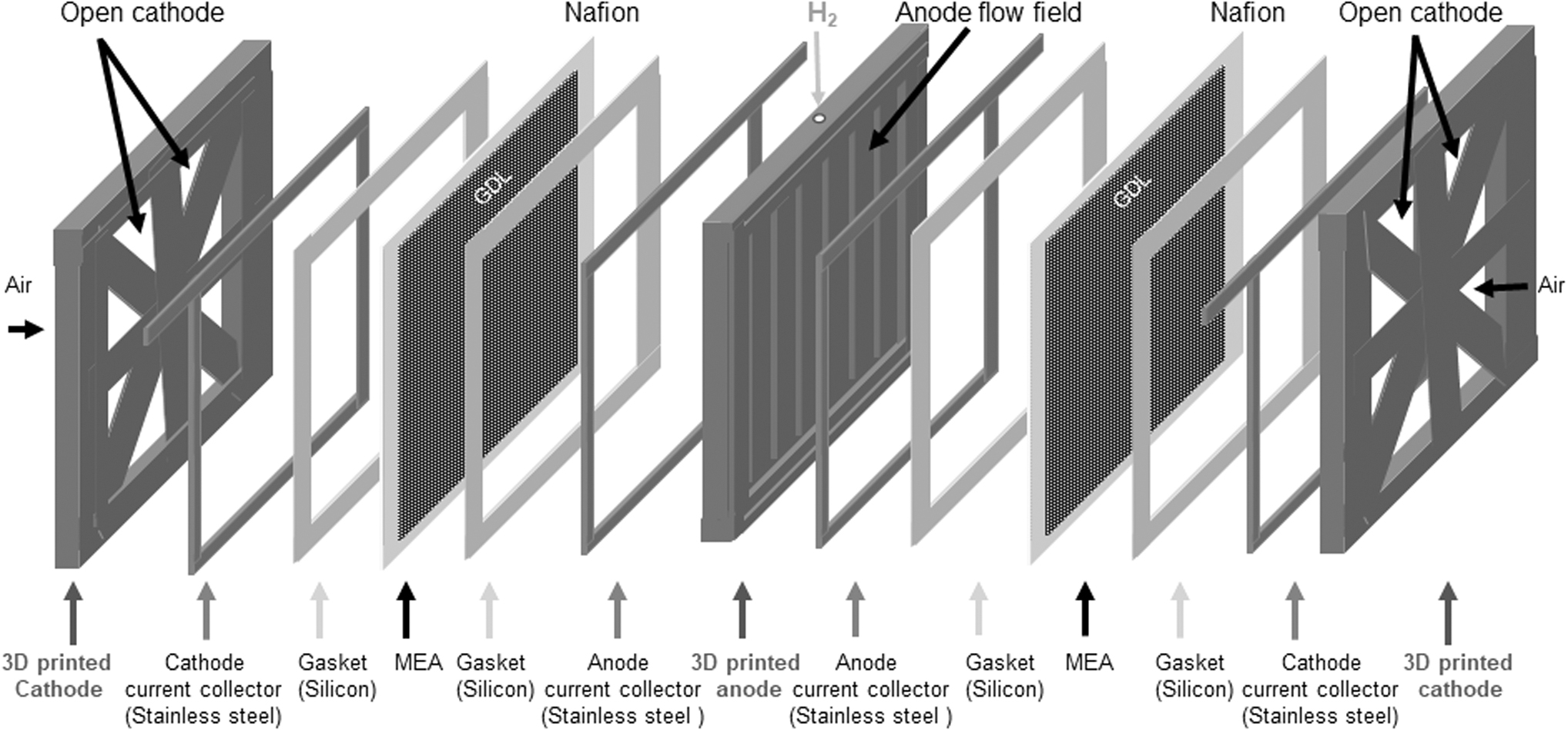
Schematic of the self-breathing stack assembly, showing the 3D printed anode, stainless steel current collectors, silicon gaskets, MEA and 3D printed air cathode. The components shown are for two cells sharing the common anode plate. MEA, membrane electrode assembly.
The gasket is made of silicon because silicon has a low permanent deformation (5% at 50°C) under compression stress and as such silicone is suitable for long-term use as a sealing material. The choice of silicon was also guided by its satisfactory tolerance to acidic environment (<1% change in weight at 10% H2SO4) and good thermal stability (−70 to 350°C).
Fabrication of the self-breathing PEMFC stack
The 3D model of the 12-celled self-breathing PEMFC stack once designed with Autodesk Fusion 360 was transferred to the 3D printer (Formlabs). The printer is based on the Stereolithography (SLA) technology, where a laser is used to cure solid isotropic parts from a liquid photopolymer resin. The Draft V1 Resin was used for the printing. Once the printing of both the anode and cathode plates was completed, these were washed in 2-propanol for 10 min and cured at 60°C for 5 min in air.
Preparation of the MEA
Twenty-four milligrams of 40%Pt/VC was added to a vial and on top, 125 μL of Milli Q water, 100 μL Nafion 10% in water and 500 μL of 2-propanol were added. The final volume was adjusted by adding 1.5 mL of 2-propanol. The mixture was sonicated for 5 min and left to stir overnight at a room temperature. The catalyst ink was dispersed on the microporous layer of a GDL using the doctor blade technique and then dried in an oven at 60°C for 1 h. Nafion 212 was used without pretreatment and the MEA was formed by placing the catalyst-coated GDL on either side of the Nafion membrane and by hot pressing at 0.18 MPa at 90°C for 2 min. Pt loading on both the anode and the cathode was 0.3 mg/cm2 and the ionomer content in the catalyst layer was 30%. Fuel cell testing was done at ambient condition (25°C, 1 bar pressure) with dry hydrogen and under a RH of 20% RH. The water contact angle was measured by using an Attension from Biolin Scientific.
Stack assembly
For the stack assembly (Fig. 2), the current collectors were placed on the respective slots of both the anode and the cathode end plates. The assembly process started by first placing the stainless steel cathode current collector. Then the silicon gasket was placed on top of the current collectors. Six MEAs were arranged within the gasket's slots. Once the MEAs were placed, the second silicon gasket was added. The anode plate was finally placed above the second silicone gasket. Finally, the assembly was fastened by nylon nuts and bolts.
Results
The effectiveness of the flow field design was simulated by using CFD modeling. As shown in Figure 3a and c, uniform distribution of H2 across the parallel channels was observed. Similarly, the evolution of the H2O formed under the simulated conditions, across the cathode reservoirs, and single-cell anode is shown in Figure 3b and d and this suggested that the proposed flow field design was not only appropriate for enabling uniform hydrogen distribution across the cells and stack but also effective water removal from the cells/stack.

CFD simulation of the stack and a single cell,
Printed anode
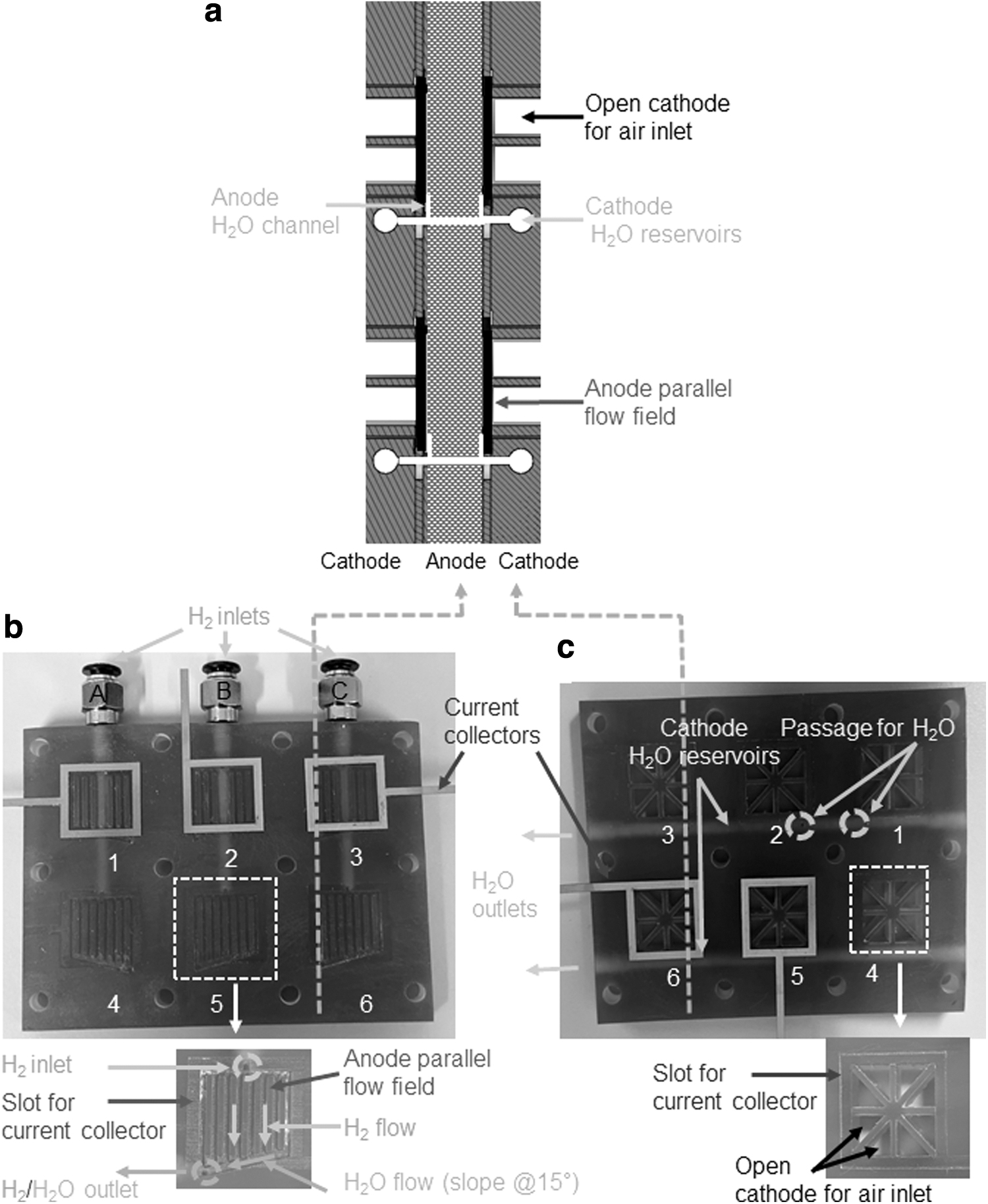
Figure 4 shows the 3D printed anode plate with the parallel flow fields across the six cells. The anode chamber for each cell has an area of 2 cm2 where parallel flow fields of 1 mm width and 1 mm height have been printed. The H2 inlets, placed at the top of the flow field are connected to a gas pipe fitting (Fig. 4b, noted as A–C) and linked to a distribution channel of 3 mm in the body of the plate to feed the individual cells (H2 inlet on Fig. 4b).
3D printed self-breathing PEMFC stack with 12 cells:
At the bottom of the flow fields, a groove with a 15° slope corresponding to the ideal slope for evacuating water from the cell 45 has been implemented (Fig. 4b). This is important to store excess water and delay any anode flooding particularly at low operating hydrogen pressures. The groove at the bottom of the flow field can be considered as a water reservoir (Fig. 4b) with a total capacity of 0.5 mL for the entire stack. This groove is also connected through a 1 mm hole to the cathode reservoir where water can escape (Fig. 4a, c). It is noteworthy that the hydrophobic nature of the 3D printed plates is also expected to ease the movement of water out of the stack. 46 Indeed the water contact angle measured on the 3D printed plates is 90.9°. Finally, a slot of 0.2 mm height and 2 mm width was made around the perimeter of the flow field to host the stainless steel current collector (Fig. 4b).
Printed cathode
Figure 4c shows the 3D printed cathode end plate. Around 55% of the active cell area is exposed to the atmosphere, and this allows for direct contact of the MEA with atmospheric air. The optimum opening of the air cathodes reported in the literature is 52% of the active area while operating at 20% RH to allow for sufficient membrane hydration while avoiding drying/flooding upon over/under water evaporation.47,48
The hydration of the membrane is maintained by the back diffusion of water from the cathode to the anode. The amount of diffusing water depends on the cathode opening, for example, it has been reported that 16% of the total H2O produced diffuses back through the membrane at 40% cathode opening when the cell is operated at 0.15 A. 48 In the current case, it can be assumed that for 3 W (1 W power and 2 W equivalent heat) operation, among the 1 mL of water produced in 1 h, around 0.16 mL will diffuse back through the membrane to maintain its hydration. This means that H2 humidification is not needed.
Similar to the anode side, a slot for hosting the stainless steel current collector was also implemented along the perimeter of the cathode opening. A passage underneath each open cathode was also created to allow excess water from the anode reservoir to move into the cathode reservoirs (total capacity 2.7 mL), where water is evacuated outside the stack (Figs. 1 and 4a–c). These reservoirs are useful mainly during the operation at low H2 pressure to maintain sufficient hydration of the Nafion membrane.
Gasket, MEA, and stack assembly
Figure 5a shows the silicon gaskets (0.22 mm thick) used for sealing the stack. The thickness of the gasket was chosen to achieve a 25% of MEA compression. No additional sealing adhesives were used.
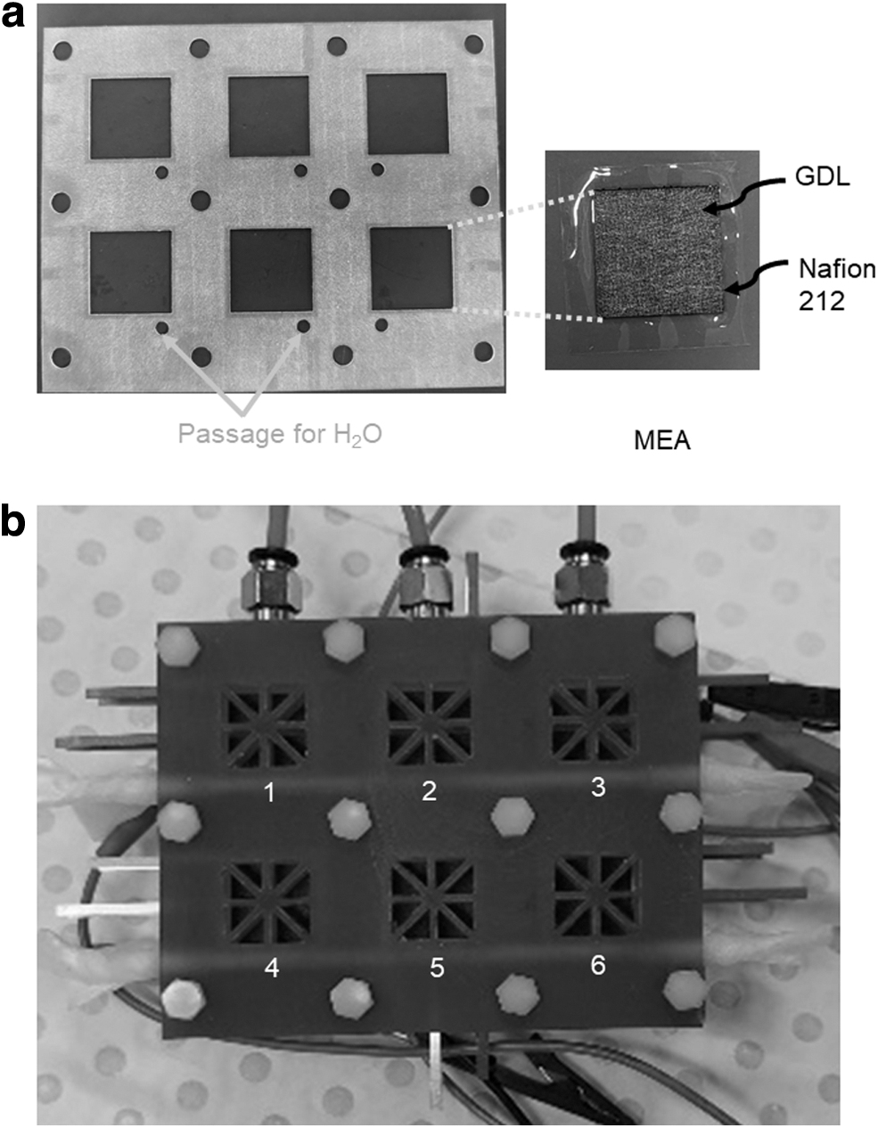
These gaskets have six squared open slots through which the MEA are exposed to air (Fig. 2). Additional open holes have been made for the mounting screws and the H2O outlets (Fig. 5a). Within the MEA, the size of the Nafion 212 membrane was kept larger than the active GDL/catalyst area to allow for an effective sealing along the MEA and electrical insulation between the anode and the cathode side of the MEA.
During the stack assembly, it is important to ensure all the components are in the right position. This was done by using the nylon nuts as a guide (Fig. 5b). Once the stack was fully assembled, full integrity of the cells was verified by testing the electrical continuity between the MEA (cathode side) and the cathode current collector with a multimeter and ensuring that there was no short circuit between the anodes and respective cathodes. The H2 leak test was done by filling hydrogen at the anode side to 1.5 bar and checking for leaks with a hydrogen leak detector. The terminal current collectors were connected in series for voltage maximization of 10 V. After completing all the tests, the stack was purged for 30 min with a constant flow of H2 at 19 mL/min.
As discussed earlier, generation of 1 W power would produce heat equivalent to 2 W. This means that during operation, the temperature of the stack would increase from 25°C to 27.5°C, (calculated considering the thermal conductivity of resin as 0.2 W/[m·K]).
Fuel cell testing
The self-breathing PEMFC stack was tested at an ambient condition (25°C, 20% RH, and by using dry H2). During this test, the MEA is exposed to the environment, so the hydration levels of the membrane is assumed to be equivalent to the RH of the room. With all the cells connected in series, the voltage against current density and power density against current density curves are shown in Figure 6a and b, respectively. The average voltage obtained from each cell is 0.72 V (at 1 mA/cm2). From this, the efficiency of the stack was calculated by considering the lower heating value of hydrogen 41 and determined to be of 55%. This performance is satisfactory considering self-breathing mode of the stack. The stack was further operated for 2 h at 76 mA/cm2 and a stable voltage of 4.7 V was obtained throughout the operation (Fig. 6c).
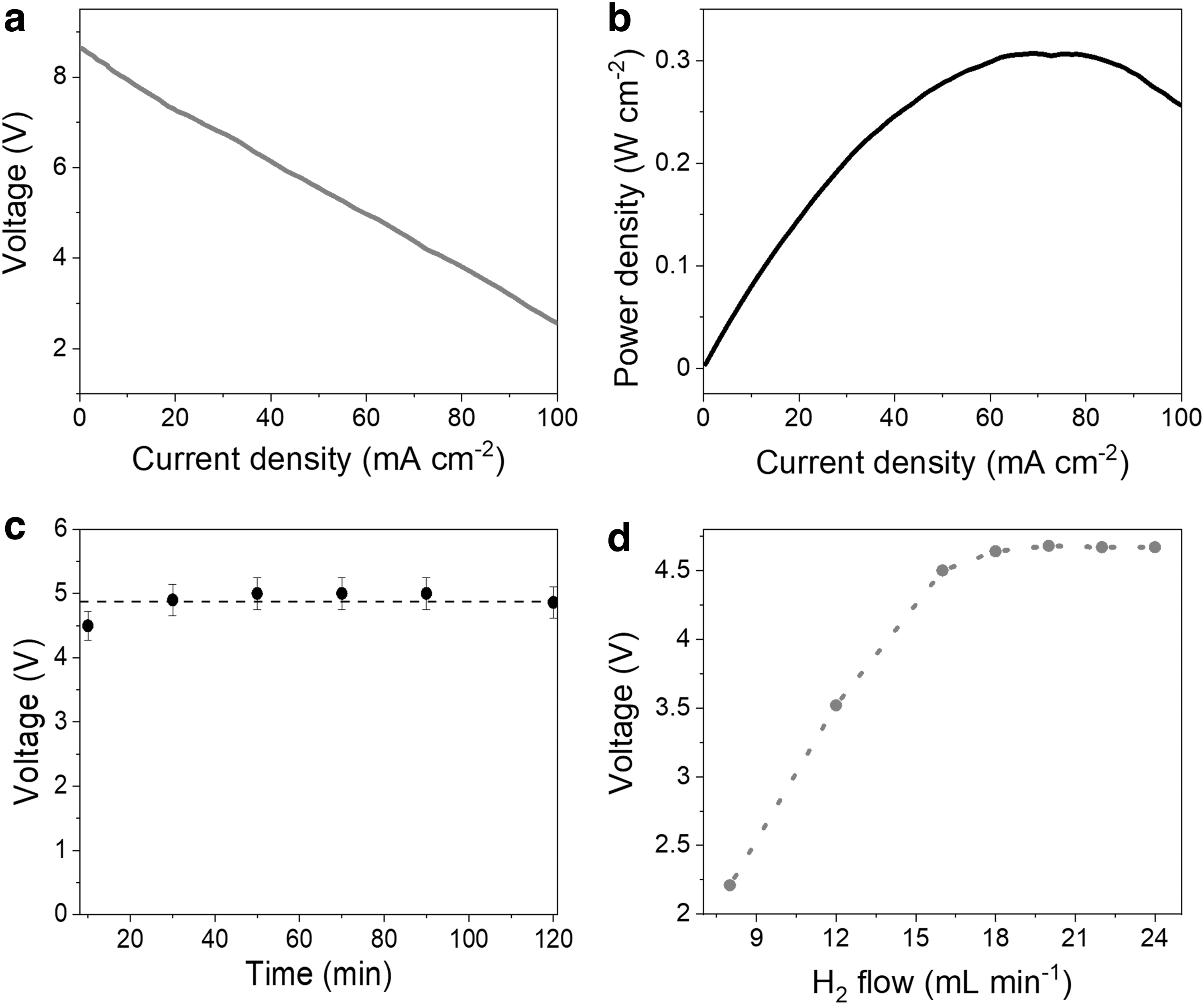
Performance of the 3D printed self-breathing PEMFC under ambient condition (1 bar, 25°C, 20% RH and dry hydrogen),
Finally, the optimum H2 requirement of the stack was confirmed by operating the stack at various flow rates. The voltage output increased with higher H2 flow and a reached maximum voltage of 4.7 V at a H2 flow of 18 mL/min (Fig. 6d). This value is close to the calculated value of 19 mL/min. Overall, the stack could deliver a maximum power density of 0.3 W/cm2 at 76 mA/cm2 operating at ambient condition (25°C, 20% RH) with dry H2 (Fig. 6b). This performance is superior compared with previously reported results. For example, a 10-celled self-breathing PEMFC stack with each cell having an active area of 9 cm−2 and gold-plated metal current collectors only delivered 2.30 W (0.25 W/cm2) at the ambient condition with dry H2. 49
Discussion
Current self-breathing PEMFCs reported in the literature are made from polycarbonate 49 and polydimethylsiloxane. 50 Their fabrication process involves thermal imprinting, 49 sealing adhesives that are often not durable under acidic operating environments, and extensive manual assembly, where staking is done by piling the individual cells. 50 This leads to stacks that are heavy and bulky in particular when commercial graphite bipolar plates are used. 51 Graphite composites and other conductive metals are also prone to electrical short circuit upon stacking and this inevitably leads to solutions that are overdesigned.
From the results above, it is thus apparent that the approach of using a photopolymer resin to 3D print bipolar plates enables new levels of flexibility in the design and arrangement of self-breathing fuel cells, and this has the potential to facilitate miniaturization. 1 The 3D printed parts accurately resembled the model designed in Autodesk Fusion 360. The minute details such as 1 mm opening and 0.2 mm engraved slots for current collectors and the water reservoirs were well printed. The groove at 15° at the anode had the advantage of stopping water accumulation at the anode chamber to enable better H2 distribution. The approach also facilitated the implementation of a simple silicon gasket to effectively seal the entire anodic chambers without any additional adhesives.
In the current design, stainless steel current collectors provided a cheap alternative to the most common gold-plated solutions49,52; and these could be replaced by simply depositing a metal coating at the surface of the bipolar plates to collect current across the cells. Further improvements could see the development of more advanced manufacturing techniques where most of the fuel cell components, including the MEA are fully printed, 29 for example, through a continuous rolling process. Additional automation could lead to the continuous manufacturing of a fully assembled stack. 53
Some work has been previously reported on the development of PEMFCs using 3D printers where individual bipolar plates were fabricated and the stacks were formed by following conventional PEMFC stacking assemblies. 24 The cell/stack were operated by supplying fully humidified (100% RH) H2 and air,24,25 and the performance of these stacks was lower than stacks built by using conventional bipolar plates (Table 2). However, none of these developments leads to the printing of a stack with multiple cells in a single print. The proposed design and method of manufacturing minimizes the overall size and cost of the stack in comparison to the individually printed and assembled stacks. Cost estimation, material and time saving, and comparison with other manufacturing process is beyond the scope of this work but 3D printing is already proven to be a low-cost and low-waste alternative in comparison to existing manufacturing technologies.54–57 As such, this work provides new avenues to those wishing to develop and customize their own stacks.
Comparison of 3D Printed Polymer Electrolyte Membrane Fuel Cell
DMLS, direct metal laser sintering; RH, relative humidity; SLS, selective laser sintering.
Although the concept presented in this work is for self-breathing PEMFCs, it can easily be translated to conventional PEMFCs, where air/O2 is supplied at the cathode with a fan. For this the open cathode should be replaced with plates akin to the anode design. In this context, it could be argued that the proposed approach of utilizing photopolymer resins to mass produce fuel cells will lead to more plastic waste, because photopolymers are difficult to recycle. 22 However, recent progress has shown that thermoplastic printed parts as well as thermoplastic wastes can be recycled and reused to prepare filaments for 3D printing. 58 In addition, the recent emergence of biobased and biodegradable polymers could provide a path toward “sustainable” fuel cells. 22
Conclusions
We have demonstrated a complete route to design and fabricate a self-breathing PEMFC stack using a 3D printer. Apart from massive reduction in cost, we show that customized fuel cells with complex geometries can be easily fabricated by using a 3D printer. Components as small as 0.2 mm were successfully printed, and this demonstrates the level of details that can be achieved without using conventional and more difficult machining approaches. The stack had 12 cells embedded in a single plate and this enabled for a compact design because of the nonconducting property of the resin. In addition, both the anode and the cathode plates were fabricated in one print, which not only minimized the fabrication time but also reduced the amount of photopolymer resin to be used.
Overall, the stack delivered a maximum power density of 0.3 W/cm2 at ambient condition (25°C, 20% RH) with dry hydrogen at a flow rate of 19 mL/min. This is far superior compared with the previously reported performances of self-breathing PEMFC stacks. Further reduction in the thickness of the plates, and removal of all “unnecessary plastic” in the bipolar plate could lead to additional improvements in terms of power to weight and volume ratio, and finally provide a path for small fuel cells of high-power density. The process is scalable as per the power requirement and the size of the 3D printer and could be applied to develop conventional H2/O2 PEMFCs.
Footnotes
References
Supplementary Material
Please find the following supplemental material available below.
For Open Access articles published under a Creative Commons License, all supplemental material carries the same license as the article it is associated with.
For non-Open Access articles published, all supplemental material carries a non-exclusive license, and permission requests for re-use of supplemental material or any part of supplemental material shall be sent directly to the copyright owner as specified in the copyright notice associated with the article.