




Abstract
Personalized insoles manufactured with selective laser sintering (SLS) technology are popular especially for exercisers and patients with foot diseases. However, insufficient strength and toughness of personalized insoles would result in crack and even fracture. To address these deficiencies and fill the research shortages in this area, optimization of process parameters and design of cell structures are conducted to improve the mechanical performance of insoles in this topic. First, six sets of process parameters in terms of energy density were designed for parameter optimization. The energy density of 0.08 J/mm2 was affirmed to be the finest selection. Then, specific cell structures featuring both whale shark and ancient soldier armor (WS structures for short) with various curvature radius were established to act on the bottom of the insole to further strengthen the personalized insoles. It was shown that the WS14 structure exhibited the best performance characteristics. Finally, a personalized insole with the array of WS14 structures was developed with SLS under the optimum energy density of 0.08 J/mm2. Finite element method analysis and exercising testing were performed to evaluate the insole performance. The result reveals that a more uniform stress distribution is attained of the WS14 personalized insole, and the fracture problem is indeed solved.
Highlights
Process parameter optimization is conducted to achieve the optimal sintering performance.
Specific cell structures are designed and their properties are evaluated through the strength and toughness.
The personalized insole with parameter optimization and WS structures results in improved strength and uniform foot pressure.
Introduction
Additive manufacturing (AM) is a flexible manufacturing technology that produces pieces in a layer-by-layer fashion through the definition of the required geometric shapes under computer control. In a general sense, this technique creates the required geometry by repeatedly depositing, curing, sintering, or combining one layer of the part at a time. As a result of its similarity to digital printing, AM is also termed 3D printing.1,2 Selective laser sintering (SLS) technology, as an important process of AM technologies, has the ability to manufacture parts with complex geometries faster than traditional technologies. 3 This process selectively sinters the paved solid powder layer by layer through a laser, such that the powder material is initially melted, then cooled, and condensed into a final three-dimensional solid part.
Materials currently available in the SLS process include metals, ceramics, and polymers. By virtue of the lower cost and melting temperature, polymer materials have attained much more applications. 4 Because Polyamide12 (PA12) has preferable biocompatibility and higher strength, it is widely used in the SLS process. In recent years, the requirement for SLSed functional parts, instead of repaid prototypes using PA12 material, has substantially increased. The personalized insole manufactured with SLS technology, as a typical of functional parts, has attracted more attention as it is thought to bring extreme comfort experience and exercise assistance for humans. However, the personalized insole is confronted with trouble of facture especially when doing exercise. The reason is that the mechanical performance of SLS, including strength and toughness always fails to reach the criteria for functionally personalized insoles. As a consequence, it is extremely necessary to improve the performance of personalized insoles manufactured by SLS.
The sintering performance of polymer materials in the SLS process is generally inseparable from process parameters, such as scanning speed, laser power, layer thickness, etc. 5 Flodberg et al. found that a too low or too high scanning speed and a too thick powder layer may incompletely melt the power particles of diameter more than 100 μm, thereby affecting the mechanical properties of the final sintered part. 5 Sutton et al. believed that the powder size and size distribution affect the fluidity and uniformity of the powder layer, resulting in impaired part performance. 6 Hofland et al. observed that scanning distance and layer thickness influence part performance in particular, followed by scanning speed, preheating temperature, and laser energy.7,8 Gazzerro et al. concluded that one of the extreme limitations of SLS formability is the aging of PA12 powder, and the sample made from the original powder has the supreme performance. 9 According to the above researches, it is particularly important to optimize the process parameters to improve the sintered performance for meeting the requirement of the personalized insole.
Personalized insoles have been of great interest because a custom insole following an individual's foot character can significantly reduce sole pressure and protect foot. 10 Textured insoles and orthopedic insoles are the two common types of personalized insoles on the market today. The so-called textured insole is covered with a designed pattern on the bottom of the insole, which is a simple and low-cost intervention to improve balance in the elderly. 11 At the same time, it can reduce excessive plantar pressure and play a certain healing effect on the premise of insole comfort. 12 A textured insole can also improve the gait asymmetry of a stroke patient and achieve the purpose of rehabilitation. 13 In contrast, orthopedic insoles are characterized with a medial plantar support, heel cup, and metatarsal pad. 14 Orthopedic insoles for sports and physical activities have been proposed and proved to have functions of reducing the risk of injury, aligning the skeleton, and improving comfort. 15 Studies have found that full-contact insoles have gained popularity in recent years because they fit the individual's foot well and provide a pleasing foot experience. 16
Diabetic foot is one of the most common complications of diabetes. A full-contact insole has been proved to reduce the peak contact pressure effectively, thereby reducing the possibility of foot ulcers of diabetic patients.17,18 To further take advantage of the full-contact insole, in our previous study, based on 3D scanning and SLS technology, parametric modeling was adopted to develop a foot-fitting personalized insole with unit arrays below the insole surface. It was demonstrated that the fitted insole can reduce the peak contact pressure by 30% compared with a flat insole, and also proved that the cellular structure array plays a crucial role. 19 However, the insole strength is not satisfactory especially when doing exercises. Optimization of cell structures should be conducted to further improve the insole performance.
In conclusion, a personalized insole with an array of textured structures or cellular structures is beneficial for foot health, especially for exercisers or patients with foot disorders. However, the final insole performance is closely related to the cell structure array and SLS process parameters. Therefore, based on PA12 material, six sets of process parameters were initially designed in this study in terms of areal energy density (AED) and the optimal parameters were determined in view of mechanical properties and scanning electron microscope (SEM) analysis. Then, three types of cell structure featuring both whale shark and ancient soldier armor were modeled, and their properties were evaluated through the strength and toughness of the SLSed samples embedded with the designed cell structures. Afterward, the selected cell structure was adopted to develop a personalized insole of which the performance was assessed through finite element (FE) analysis and exercising testing.
Experiments and Methods
Wavier statement
The study is in the process research stage now, and it has not been applied to clinical treatment. Therefore, all experiments in this paper do not involve human or animal subjects, and this behavior also do not violate ethics.
Experimental design of optimization of process parameters
The pure PA12 powder used in this experiment is strictly in accordance with the 2:8 mixing of the used and new powders. Additionally, the equipment used for sintering in this experiment is the SLS machine produced by Wuhan 3DPAction Co., Ltd. In this study, six sets of process parameters were designed for process optimization based on the indicator of AED. This scheme is mainly characterized by the combination of laser power P and scanning speed V, as shown in Table 1. In our previous work, the effect of AED variation (0.016–0.14 J/mm2) on the sintering performance has been conducted. It was found that either a too low or too high AED will lead to a decreased mechanical performance owing to a large volume of porosity. 20 Therefore, only the energy densities between 0.04 and 0.09 J/mm2 contained in Table 1 are considered as significant defects may occur if a smaller or larger energy density is adopted. In addition, in view of the material characteristics of the PA12 powder, all the SLS experiments were conducted under a preheating temperature of 170°C and a powder base of 8 mm thickness.
Process Parameter Design
AED = 4P/πvh.
AED, areal energy density.
Mechanical experiments of regular parts
Tensile, flexural, and impact experiments were conducted to evaluate the mechanical properties of the SLS under the design process parameters shown in Table 1. The size of the tensile samples is 165 × 20 × 4 mm, and five samples for each AED were processed. Tensile experiments were performed at a rate of 20 mm/min according to the ISO 527 standard (ISO527. 2:2006). The samples for bending and impact tests have a size of 80 × 10 × 4 mm. Five samples for each AED were processed for 3-point bending tests according to the ISO 178 standard (ISO178: 2010), while 10 samples for impact toughness tests in the light of the ISO 179 standard (ISO179-1:2010). Finally, the average values of tensile strength, bending strength, impact strength, tensile modulus, and flexural modulus were compared for the determination of the optimum set of process parameters.
Cell structure design
Based on the structural features of both whale shark and ancient soldier armor, a characteristic cell structure (abbreviated as WS structure) was designed to further improve the mechanical performance of personalized insoles, as shown in Figure 1. This design not only has the same strong protection ability with soldier armor characterized by three symmetric ridge-like shapes, but also has a bionic streamlined arc surface, similar with whale shark, to evenly distribute the pressure. The distributed pressure of the WS structure can be clearly illustrated by the normal stress formula

Cell structure design.
Figure 2 shows the specific parameters of the WS structures with three different curvatures, which were modeled in Rhino software for subsequent analysis. The WS structures consist of three identical units of ridge-like shape, which are symmetrically distributed. First, the ridge-like units are developed from a frame with a length of 3.0 mm, a width of 2.6 mm, and a changing height of 1.0, 1.2, and 1.4 mm. Second, the two same ridge-like units are grouped and the height of the intersection area between them is kept at 2.1 mm. Then use the interpolation curve to connect the upper points of the frame to form an arc curve, and a cell element can be finally obtained. The WS structures with the height of 1.0, 1.2, and 1.4 mm, termed as WS10, WS12, and WS14 structure in turn, has the calculated average curvature radius of 4, 5, and 6 mm, respectively. 19

Detailed parameters of the cell structure.
Mechanical experiments of parts with cell structure
To evaluate the performance of the designed cell structures, the WS structures were arrayed and then embedded into the tensile, bending, and impacting samples for the following mechanical experiments. The schematic diagram is shown in Figure 3. All samples were sintered under the optimal set of process parameters and the appropriate cell structure was determined in view of their mechanical properties. Afterward, the selected WS structure was introduced for generating the cell array for a personalized insole.

Samples embedded with WS Structures. WS Structures, cell structures featuring both whale shark and ancient soldier armor.
Personalized insole simulation
The WS structure with supreme mechanical performance was selected for the modeling of personalized insoles with cell arrays according to the method provided in our aforementioned research. 19 To evaluate the performance of the developed custom insole, a FE model consisting of a foot, an insole, and the ground was established in ABAQUS software as shown in Figure 4. At the same time, the stress distributions of the personalized array insole and the nonarray insole were compared. A 40-year-old healthy man weighing 70 kg was taken as the example. The material of insoles was PA12. For the sake of convenience, the foot component was simplified as a whole integrity, and the ground is replaced by a flat plate. In addition, the ground and the foot were set as rigid bodies for simplicity. The Young's modulus of the insole is fitted by the compressive stress–strain curve of the PA12 material and set to 1.15 MPa. 19
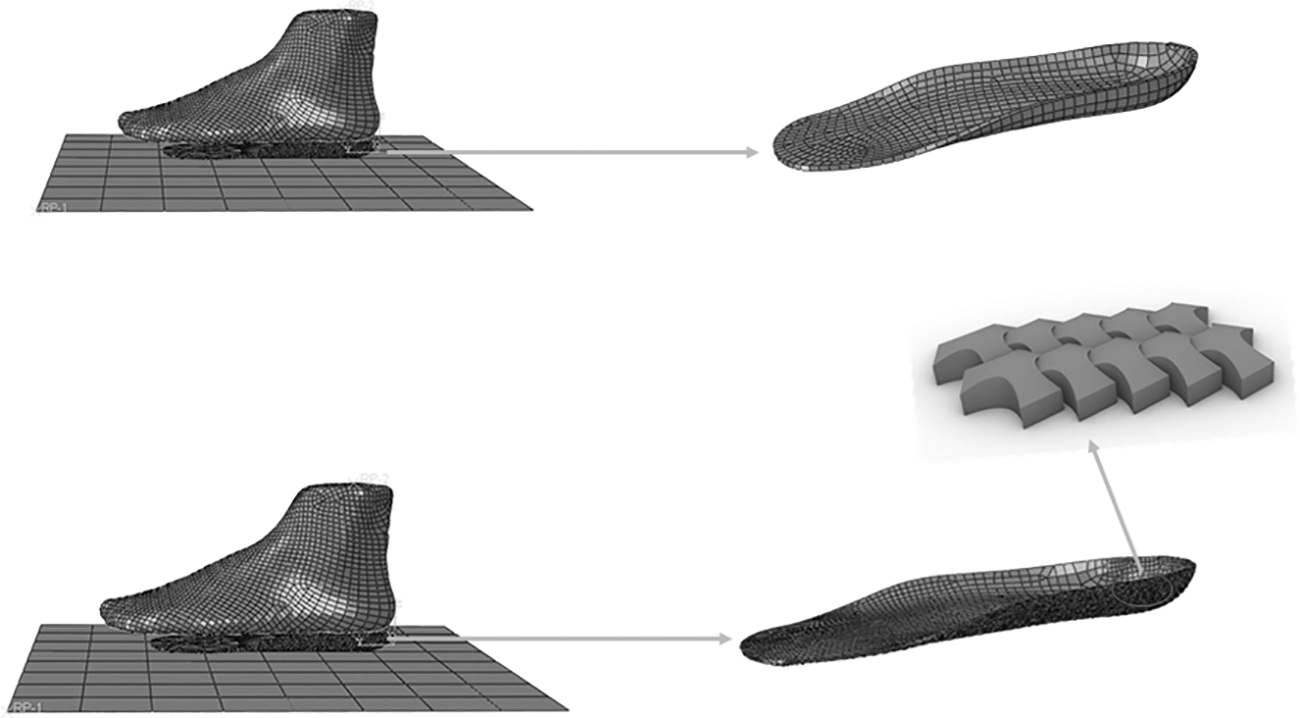
Personalized insole simulation.
Due to the complex structure of insoles, the personalized insoles were meshed with Hypermesh software for mesh fineness, while the other components were directly meshed in ABAQUS. All the components in the FE model were meshed with tetrahedral and triangle elements. Additionally, for a balance of efficiency and accuracy, the cell structures and other components have a mesh size of 0.1 and 5 mm, respectively. Eventually, a downward displacement of 20 mm of the foot was applied as a boundary condition to analyze the deformation of the two kinds of insoles.
Results and Discussions
Mechanical performance
Tensile results
The tensile parts processed by SLS for parameter optimization are shown in Figure 5, in which all the samples have an agreeable appearance and neither curling nor other obvious defects occur. For an easier visualization and interpretation of the results, Table 2 exhibits the obtained average mechanical properties of the samples while the detailed data are comparatively plotted in Figure 5.

Tensile performance
Mechanical Performance Test Results
It can be seen from Table 2 and Figure 5 that with the increasing energy density, the tensile performance improves initially, experiences a relatively stable stage, and then decreases notably. Higher values of strength were recorded for higher energy densities at a relatively equal condition. Specifically, when the energy density of 0.04 J/mm2 is set, the least tensile strength of 37.68 MPa and elasticity modulus of 2137.08 MPa are attained. Meanwhile, the third group with the energy density of 0.06 J/mm2 has the supreme performance, with the maximum tensile strength of 48.06 MPa and elastic modulus of 2427.63 MPa. Furthermore, it is evident from Figure 5c that when the energy density is in the range of 0.05–0.08 J/mm2, there is little difference for the average tensile strength of the sintered parts. However, as plotted in Figure 5b, the elasticity modulus of the energy density of 0.08 J/mm2 is lower than that under other conditions, which is thought to be more in line with the comfort requirements of insoles.
The reason why the strength at the energy density of 0.05–0.08 J/mm2 is agreeable is that the degree of particle melting increases with the increase of energy input and further leads to a reduction in viscosity and porosity, thereby resulting in an improved tensile strength. 21 Comparatively, when the energy density reaches to 0.09 J/mm2, it leads to the decreased tensile property. This phenomenon can be accounted that when the energy density is too large, the force of the laser on the powder molecules is increased significantly, therefore breaking the molecular chains between the powders, destroying the original molecular structure, increasing the overall pores of the parts, and reducing the mechanical properties of the parts.22,23 This is also consistent with Ling's research that an excessive energy promotes porosity. 24
Bending and impact results
Figure 6 shows the manufactured parts for bending experiments, and the bending strength, flexural modulus, and impact strength as a function of energy density. Table 2 also shows the detailed data of bending performance under different energy densities. It is clear that the energy density of 0.05 J/mm2 results in the maximum bending strength of 59.44 MPa. As shown in Figure 6b, the bending strength increases from the beginning and then declines thereafter with the increasing energy density, exhibiting a similar trend to tensile strength in Figure 5c. Besides an increase in part properties with an increasing energy input, a relatively linear increase in overall impact strength was observed in Figure 6d. Correspondingly, an energy density of 0.09 J/mm2 leads to the maximum impact toughness of 138.19 kJ/m2. However, exploring the turning point of the overall trend of strength can find that when the energy density is 0.06 J/mm2, the impact strength presents a significant downward trend. One possible explanation for this special case is the strength fluctuation aroused by inadequate crystallization process.

Bending and impact performance
As the energy density further increases from 0.06 J/mm2, more particles are melted and involve in recrystallization. The pores in the powder bed filled with the crystalline phase, gradually disappear or reduce to tiny pores and, therefore, form a dense structure. It turns out that these tiny pores may hinder crack propagation and thus improve plasticity and toughness. 25 This can also explain why the impact strength increases with the increase of energy density. At the same time, when the energy density reaches the upper limit, it yields to the best impact strength, but the flexural response decreases. Therefore, a suitable energy density should be compromised for a satisfying comprehensive performance.
SEM analysis
The scanning electron microscopic topography of the fractured surface of PA12 samples under different energy densities are depicted in Figure 7. It can be seen that when the energy density is between 0.04 and 0.07 J/mm2, the processed parts have obvious unsintered particles, interlayer pores, and distinguishable layers. The maximum size of these interlayer pores is around 100 μm. This will lead to reduced mechanical properties of the specimens compared with perfectly sintered parts. Figure 7e clearly shows that when the energy density is as high as 0.08 J/mm2, there are almost no pores or unsintered particles, and a near dense structure is attained. The result correlates well with the strength analysis mentioned in Mechanical performance section and is consistent with Johannes Schneider's research. 26 However, when the energy density reaches to 0.09 J/mm2, the powder particles are overheated by the strong laser to be evaporated.
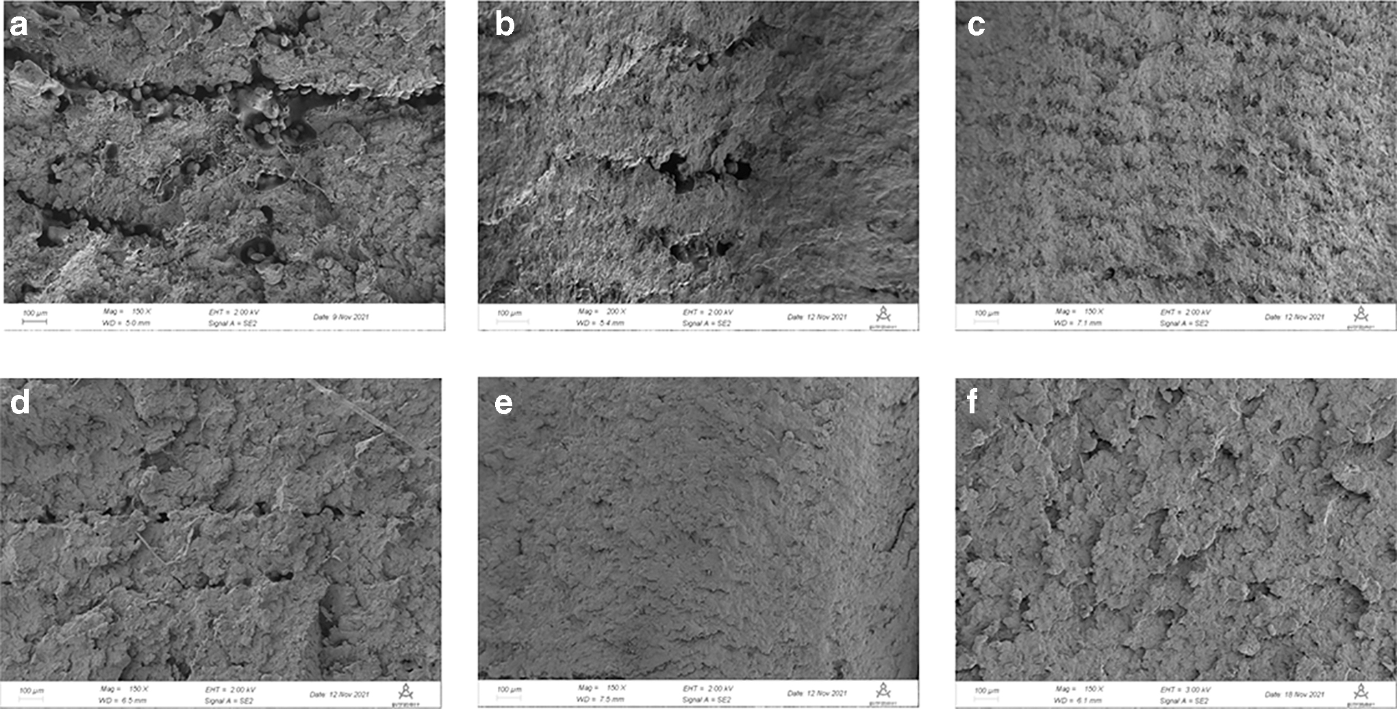
Microscopic morphology of PA12 parts under various energy densities
In this case, the surface will become rough and the new powder layer cannot be distributed evenly, resulting in a deteriorated microstructure with more pores as shown in Figure 3f. The results correlate well with the conclusion that an exceeding density will increase the porosity and reduce the performance of the sinter part.22,27,28
Considering the mechanical property requirements of functional parts, the appropriate set of process parameters should be selected through a comprehensive analysis of the achieved experimental results. Although the energy density of 0.09 J/mm2 brings about the supreme impact performance, the tensile and bending strength responses are poor. It is not desirable to manufacture functional insoles with agreeable performance under this energy density. It is noticed that energy density of 0.08 J/mm2 gives rise to the second largest impact strength as high as 86.82 kJ/m2, a satisfactory tensile strength of 47.42 MPa, which is extremely close to the maximum value, and an ultimate bending strength of 47.82 MPa. Additionally, the manufactured part under the energy density of 0.08 J/mm2 has a uniform and dense micromorphology as well. Therefore, the energy density of 0.08 J/mm2 is preferred to process the functional parts and was adopted for the following experiments in this study.
Mechanical performance of WS structures
To evaluate the influence of cell types on the mechanical performance, the tensile and bending parts embedded with the designed WS structures were manufactured by SLS using the energy density of 0.08 J/mm2 and then performed for mechanical experiments.
Tensile performance
The successfully processed tensile parts with embedded WS structures and the corresponding curves of mechanical properties are shown in Figure 8, while the average mechanical properties of the tensile samples are listed in Table 3. It can be concluded that as the height of the WS structures increases, the tensile strength exhibits a monotonically increasing trend. Specifically, the tensile part of WS14 structure has the maximum tensile strength of 76.77 MPa, which has a marked increase by about 26% compared with the WS10 structure. However, the average tensile strength of WS12 and WS14 structures exhibits little difference. It indicates that the height of WS structure has a positive effect on the increase of tensile strength but a limited influence when a critical height is reached. Additionally, the elastic modulus of WS14 is also higher compared with the other two structures, indicating that the WS14 structure is less susceptible to deformation.
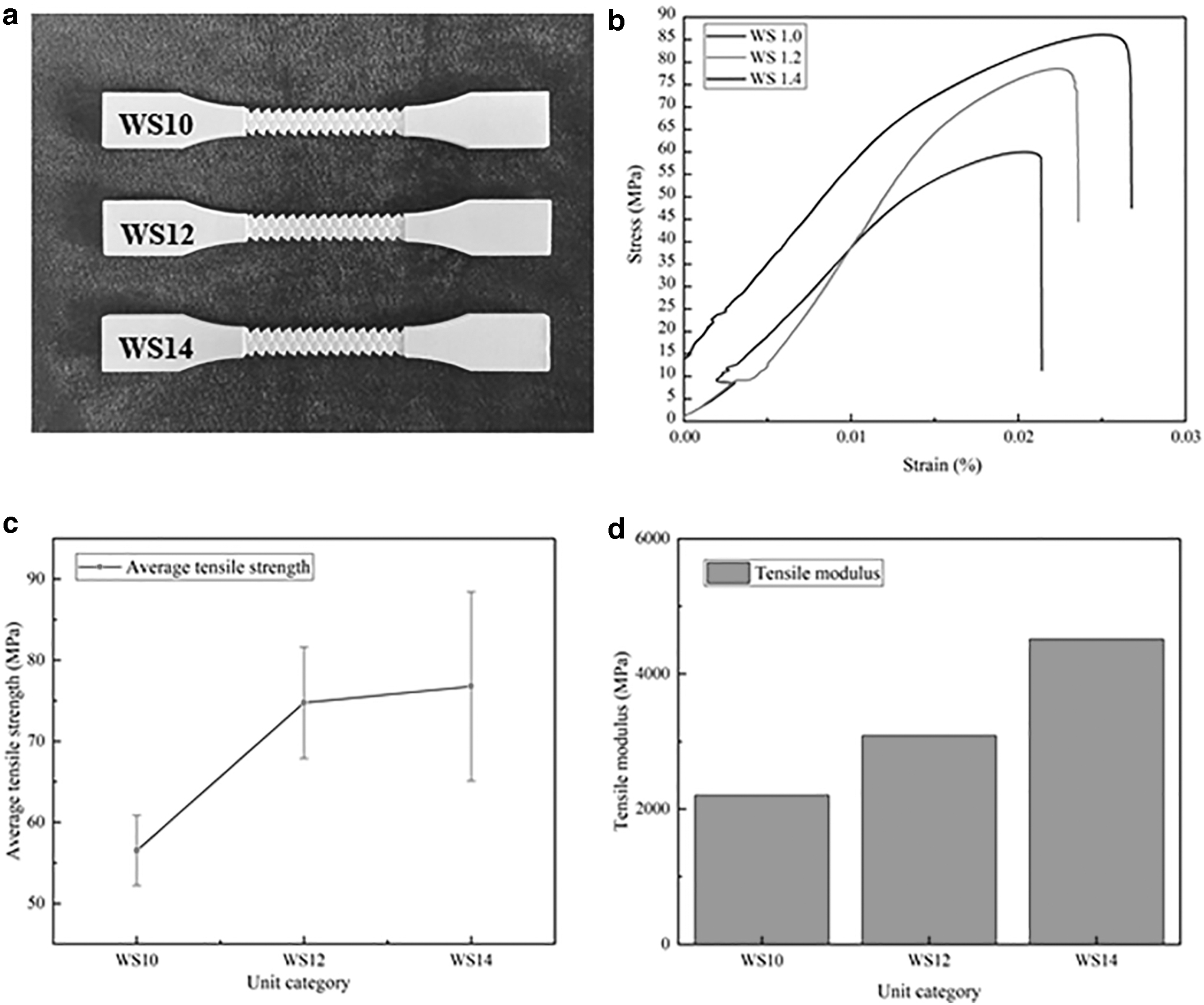
Tensile performance of samples with WS structures
The Mechanical Properties of the Tensile Parts with WS Structures
WS Structures, cell structures featuring both whale shark and ancient soldier armor.
Bending and impact performance
Figure 9 shows the bending and impact specimens embedded with WS structures, and compares their bending strength, flexural modulus, and impact strength. It is noted that the bending strength and modulus improve notably with the increase of height, showing a positive correlation between them, namely, as the bending stress increases, the bending modulus also increases in a linear manner. The tensile sample with WS10 structure has a much less bending performance owing to the higher curvature. The higher curvature gives rise to the sudden change of the cross-sectional area, which facilitates the occurrence of fracture. On the other hand, there is little difference in average impact strength between WS12 structure and WS14 structure shown in Figure 9d. This may be due to the fact that when the curvature of the curved surface of WS structures reaches a certain level, the impact stress that the WS structure can withstand remains stable. In summary, the curvature radius of WS structure should not be too small. A suitable curvature radius should be selected to obtain the best strength.

Bending performance of samples with WS structures
Insole simulation analysis
Figure 10 shows the stress distribution of the nonarray insole and the personalized insole with arrays at different displacement boundary conditions in the finite element method (FEM) model. First, it can be seen that the pressure of the nonarray insole is mainly concentrated in the heel and arch area at the initial stage with the displacement of 10 mm. Comparatively, the heel part of the custom insole with arrays is almost not under pressure and effectively avoids the stress concentration there. This result proves that the distributed arrays of WS structures can prevent the heel from being severely stressed, thereby playing a protective and cushioning effect on the foot. Second, as shown in Figure 10c, when the foot is moved downward by 20 mm, the maximum stress of the nonarray insole in minor regions is as high as 133 MPa, whereas the stress in the major regions is only between 80 and 90 MPa. It shows there is a quite uneven stress distribution and the excessive stress causes a significant mesh distortion. Meantime, when it comes to the personalized insole with WS14 arrays, the peak stress is substantially reduced by 35%.
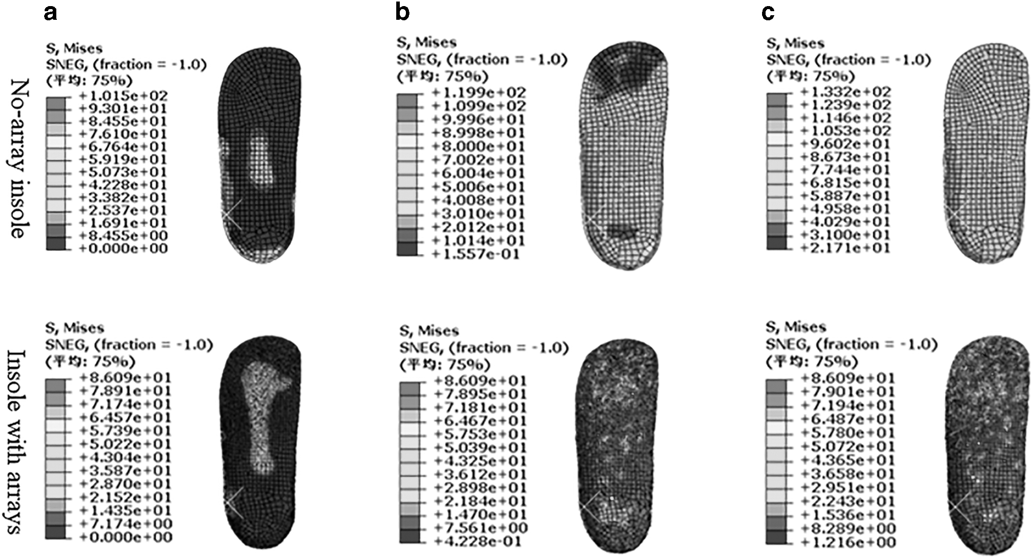
Stress distribution of insole at different displacements
The less stress attributes to the increased contact area aroused by the array of a large quantity of WS structures, thus favoring a more uniform stress distribution. The significantly reduced peak stress of personalized insole can also be experimentally verified through a Footscan system for foot pressure measurement in our previous study. 19 The experimental result shows the personalized insole can reduce the tool peak stress by 30% over the flat insole, which is similar to the simulation results verifying the effectiveness of the FEM model.
In addition, compared with the nonarray insole, there is no obvious mesh distortion of the insole with arrays under the same condition. It reveals that the arrayed WS structures also strengthen the insole to endure more load. From the perspective of comfort standard, the greater the peak pressure of the sole, the greater the possibility of damage, and the smaller the peak pressure, the more comfortable it feels. As the custom insole with the array of WS14 structures is less stressed, and has an evenly distributed stress and an enhanced strength, it is thought that the WS14 structures enable to develop personalized insoles for both agreeable mechanical performance and comfort level.
Exercising tests were also conducted to verify the performance improvement of personalized insoles with WS structures. Test subjects were asked to wear personalized insoles and perform a football workout every 2 days. As shown in Figure 11a, the insoles without optimization are fragile for exercise and fractures always occur at the beginning of testing even at the first exercise. Comparatively, when optimization of process parameters and cell structures were taken, the processed personalized insoles are still in good condition after 6 months of use. The testing result demonstrated that the proposed optimization method enables to fit well with the requirements of personalized insoles manufactured with SLS technology, being applicable to other functional parts for strength and toughness improvement.
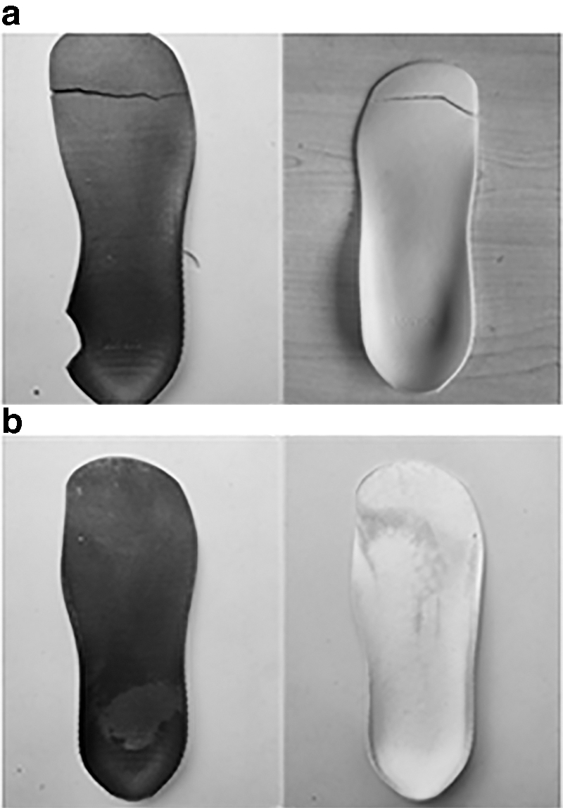
Exercising tests
Conclusions
AM functional parts through laser sintering are attracting a considerable interest from market and academic organizations. Personalized insole is a typical functional component to render comfort experience especially for exercisers and patients with foot diseases. However, the insufficient mechanical properties of personalized insole may cause local crack and even direct fracture. In this study, optimization of process parameters and design of cell structures were conducted to improve the strength and toughness of the custom insole. SEM micrograph analysis and FE simulation were also performed to evaluate the insole performance. The conclusions are as follows.
Six sets of process parameters were designed and adopted to manufacture the tensile and bending samples, of which the mechanical properties were compared to achieve the optimum energy density. Analysis of the mechanical properties versus the energy input showed that the mechanical performance increases with the increasing energy input until an energy density of 0.08 J/mm2 is reached. However, when the energy density exceeds 0.08 J/mm2, the tensile and bending performance decreases gradually. SEM micrographs confirmed that there are almost no unmelted powder particles or tiny pores at energy density of 0.08 J/mm2 as well. As a consequence, the energy density of 0.08 J/mm2 was selected for the following experiments.
Three variations of WS cell structures derived from whale shark and ancient soldier armor were developed to further strengthen the mechanical performance of personalized insole. The tensile and bending samples embedded with three types of WS structures were manufactured with SLS under the selected energy density of 0.08 J/mm2. The results of mechanical testing indicate that with the increase of the average curvature radius, the mechanical properties increase accordingly. The cell structure of WS14 has the supreme mechanical performance and was therefore utilized to develop the array below the lower surface of personalized insoles.
FE simulation and exercising testing were conducted to evaluate the mechanical performance of personalized insoles with the array of WS14 structures, which were manufactured by SLS under the optimal energy density of 0.08 J/mm2. The personalized insole with arrays was found to have a significantly reduced maximum stress by 35% compared with a nonarray insole. It demonstrates that the designed WS14 structure contributes to a more uniform stress distribution and an enhancement of mechanical performances. Exercising testing is also carried out to verify that the phenomenon of crack and fracture can be prevented even if the personalized insole experiences a long-term use. In addition, the optimization of process parameters and cell structures in this study can also be applied to improve mechanical performance of other functional parts manufactured with SLS technology.
Footnotes
Author Disclosure Statement
No competing financial interests exist.
Funding Information
The study was supported by the National Natural Science Foundation of China (Grant No. 51775069); the Natural Science Foundation of Chongqing [cstc2019jcyj-msxmX0362].