
Abstract
This study proposes a novel and simple fabrication method of magnetic microfibers, employing filament stretching three-dimensional (3D) printing, and demonstrates the capacity of four-dimensional (4D) printing of the proposed magnetic microfibers. A ferromagnetic 3D printing filament is prepared by the mixture of neodymium-iron-boron (NdFeB) and polylactic acid (PLA), and we investigate the characteristics of the ferromagnetic filament by mixing ratio, magnetic properties, mechanical properties, and rheological properties through experiments. By thermal extrusion of the ferromagnetic filament through a 3D printer nozzle, various thicknesses (80–500 μm) and lengths (less than ∼5 cm) of ferromagnetic microfibers are achieved with different printing setups, such as filament extrusion amount and printing speed. The printed ferromagnetic microfibers are magnetized to maintain a permanent magnetic dipole moment, and 4D printing can be achieved by the deformations of the permanently magnetized microfibers under magnetic fields. We observe that the mixing ratio, the thickness, and the length of the magnetized microfibers provide distinct deformation of the microfiber for customization of 4D printings. This study exhibits that the permanently magnetized microfibers have a great potential for smart sensors and actuators. Furthermore, we briefly present an application of our proposed magnetic microfibers for bionic motion actuators with various unique undulating and oscillating motions.
Introduction
As one of additive manufacturing extensions, four-dimensional (4D) printing has received a great attention by the change of shapes and functions of smart materials to external stimuli such as heat, 1 water, 2 humidity, 3 magnetic fields, 4 and more. 4D printing is accomplished by the transformation of the three-dimensional (3D) printed structure responding to these external stimuli over time, which triggers the static 3D printed configuration for dynamic morphing.5,6 Especially, in the fields of bionics, 7 soft robotics, 8 and actuators, 9 the 4D printing approach has been widely applied due to the capability of complex features and energy supplement for motion or deformation. Recently, magnetic-responsive smart materials and their structures have attracted considerable attention due to their fast response, low energy consumption, and noninvasively remote actuation. 10
A magnetic microfiber is a synthetic fiber with magnetic properties in micrometer thickness. Owing to the size and characteristics, magnetic microfibers have been widely applied for various research fields, such as actuators,11,12 microfluidic pumping,13,14 air filtration,15,16 electromagnetic wave absorption, 17 water collection, 18 biological scaffolds, 19 and so forth.
A magnetic fiber is also commonly called as magnetic cilia due to its freestanding structure when used as an actuator. Hanasoge et al. 20 used multirow magnetic composite cilia for fluid transport to pump the fluid in the microchannel, reaching a flow rate of 11 μL/min and a pressure of 1 Pa under the magnetic field. The numerical simulation quantitatively analyzed the movement of the driven magnetic cilia to predict the flow and the pressure for an optimized microfluid propulsion. Gu et al. 21 encoded a programmable magnetization pattern into magnetic cilia for metachronal waves under the dynamic magnetic fields. They developed a bionic millipede-inspired soft crawling robot to imitate the motion of African millipede and proved the programmability of the magnetic microfiber motion.
Liu et al. 22 doped iron powder in polydimethylsiloxane (PDMS) to fabricate slender and flexible microsized high-aspect-ratio cilia in different sizes up to 5 mm in length and 1 mm in width. In addition, they quantitatively studied the effect of iron powder concentration on the elastic modulus of the cilia. A single fiber exerted a driving force of 27 μN under the magnetic fields of 160 mT, and these cilia were adapted for a mixer in lap-on-a-chip applications. Lu et al. 23 also developed freestanding magnetic microfibers to convey objects under the magnetic fields.
Magnetic microfibers have also been used for air filtration and water collection. Liu et al. 24 presented a composite membrane consisting of PVDF/Fe3O4 microfibers with magnetic and electret effects for a great air filtration efficiency reaching 99.95% under the condition of 0.3 μm NaCl aerosol. He et al. 25 developed bionic spider-silk-like microfibers with controllable magnetic spindle knots, which were assembled in customized patterns by the magnetic fields. This magnetic bionic spider web-like fiber structure exhibited an outstanding water collection function.
In addition, magnetic biological scaffolds attract iron-containing biological growth factors, providing nutrients for cell proliferation and promoting cell growth, especially for bone regeneration. 26 Sun et al. 27 created magnetic alginate microfibers (MAMs) as the basic unit of biological scaffolds. Due to the high flexibility, MAMs maneuvered cells by the control of the magnetic fields, providing a nonmechanical contact delivery, thus avoiding interference and cell damage.
Various microfiber fabrication methods have been developed to accomplish the applications abovementioned, including three main approaches, molding, micromachining, and electrospinning technology. Riahi and Alizadeh used a CO2 laser to make microholes as molds on a PMMA board, and the holes were filled with Fe-PDMS to form microfibers. Although the microfiber presented high aspect ratios (the maximum aspect ratio is about 5), the uniformity of the thickness was poor by the cone-shape structure. 28 Further improvement was made to avoid the emergence of the cone shapes. 3D printed mold of microholes covered with a smooth insulating layer allowed NdFeB/Ecoflex composites to form high aspect ratio fibers (the aspect ratio is 5). 21 However, the diameter (or thickness) of the fiber was limited to 0.8 mm, and higher aspect ratios were extremely challenging by the molding method.
Hanasoge et al. 29 used surface micromachining with dual-mask photolithography to manufacture flexible hair-like cilia with nickel-iron permalloy. Although the photolithography process obtained precise (several microns or even nanometers) thickness of artificial cilia, this process is limited to metal materials, and the microfabrication requires high costs and is complex.
Yang et al. 30 demonstrated magneto-electrospinning method which produced aligned polymer fibers doped with magnetic particles through parallel magnetic fields. 30 This method overcame the disordered patterning phenomenon of traditional electrospinning, but it was limited to produce only parallel or crossed fibers. Furthermore, it was difficult to produce customized patterns and structures. The nanometer thickness of the electrospun fibers was also an issue. For independent freestanding, the thickness of a fiber should be on the order of hundreds of microns. And high driving voltage from several kilovolts to tens of kilovolts may bring potential danger if improperly operated.
Li et al. 31 presented a simple magnetic-mechanical stretching method to make magnetic microfibers. Magnetic droplets were formed at a pinpoint, and magnet bars were attached on a rotating plate. When the magnet bars were close to the magnetic droplet, the droplets were stretched on the mechanically rotating magnet and formed bridges between magnetic bars to generate continuous microfibers. This magnetic-mechanical stretching method avoided a high pressure of electrospinning or a high temperature of melt spinning, but this method is difficult to produce complex 3D shapes and specific patterns due to continuous fiber formation by the rotation.
Through analyzing the limitations of currently available approaches, in this study, we propose a 3D printing approach using a fused deposition modeling (FDM) printer to fabricate magnetic microfibers by a filament stretching method which has been introduced in our previous publications.23,32 We prepare NdFeB-doped polymer filament for FDM printing and characterize its mechanical, magnetic, and rheological properties and microstructure. The physical properties of the composite are suitable for the 3D printing fabrication processing.
The main principle of the fabrication is that the molten composite extruded through the nozzle forms a liquid bridge due to the nature of non-Newtonian molten composite, as well as longitudinal and transverse mechanical stretching during the fabrication. This new fabrication process presents the advantage in that no additional auxiliary equipment and no pre- and postprocessing are required; high-aspect-ratio microfibers can be produced with controllable thickness ranging from 76 to 455 μm (from a 500 μm nozzle), and the length of the 3D printed microfiber can be ranged from millimeters to centimeters. We further investigate the capacity of the magnetic microfibers for 4D printing as a preliminary study. After magnetization, the permanently magnetized microfibers present great potentiality for 4D printing, performing various deformation modes. In this article, we also briefly introduce an application of the magnetic microfiber for a simple bionic motion actuator with different bending modes.
Materials and Methods
Materials
A two-component magnetic polymer, NdFeB/PA12 (neodymium-iron-boron and Nylon 12) compound and polylactic acid (PLA), was prepared to manufacture magnetic microfibers. NdFeB/PA12 compound pellets (L-3088) and PLA filaments were purchased from Deqing Jingge Magnetic Technology Co., Ltd. and Raise 3D Technologies, Inc., respectively. In this study, we use NdFeB/PA12 compound pellets instead of pure NdFeB because fine particles (<100 μm) of pure NdFeB are extremely easy to oxidize. PLA is the most commonly used material for FDM 3D printing, and the rheological properties of PLA from our previous work indicate its superior compatibility with NdFeB/PA12 compound because of high viscoelasticity and printability. 33 The purchased magnetic compound and the PLA filament were used for further processes without any modification.
Magnetic filament preparation
The magnetic compound and PLA filament were initially ground separately in powder form by a commercial grain grinder. The ground magnetic compound powder was filtered by a metal mesh filter (mesh size of 100 μm) to discard larger sized NdFeB particles which cause clog in the printer nozzle during the printing. The ground PLA was controlled to reach 1 mm length to fully contact the magnetic particles with better mixing. In this work, we control the mass fraction of NdFeB/PA12 compound to be 30%, 50%, 70%, and 80%, and the volume fraction is 9.1%, 18.91%, 36.3%, and 48.9%, respectively.
Before preparing (i.e., extruding) magnetic filaments with the mixture, all ground powders were placed in a drying oven at 90° for 4 h to eliminate moisture, and then the compound and PLA powders were mixed fully by shaking before being fed into a filament extruder (Wellzoom) with 2 mm nozzle. The extruder was placed at an angle of about 30° to promote the admission of the mixed powder together, preventing the lighter polymer powder from remaining on a corner. Temperatures of the front and back zones of the extruder were set at 180° and 185°, respectively, to mix the mixture uniformly. An extruded magnetic filament was directly dropped in water for cooling and solidification. The diameter of the filament is uniformly controlled at 1.75 mm by adjusting the extrusion speed and the pulling speed of a traction wheel. We observed that the distribution of NdFeB in the filament was uneven; thus, we made a second extrusion process with the extruded filament.
We made 2 mm magnetic polymer pellets from the extruded filament, and the pellets were dried at 90° for 4 h to remove the moisture before second extrusion. The second extrusion resulted in better magnetic filaments with uniform thickness and more homogeneous particle distribution. The extruded filament was then placed in a drying oven at 40° for 2 h to be used for magnetic microfibers. Finally, we prepared four samples of magnetic filaments, namely, MF30, MF50, MF70, and MF80. The number of the sample name indicates the mass fraction of NdFeB/PA12 in the mixture. However, for the experiment, only three filaments, MF30, MF50, and MF70, were selected because the property of MF80 was not feasible for 3D printing by its fragility. The printing property of MF80 is presented in Magnetic and Mechanical Properties of the Ferromagnetic Filaments section.
Characterization of magnetic filament
NdFeB particle distribution
Three samples of the magnetic filaments were analyzed by the distribution of NdFeB particles in PLA matrix. Each filament sample was cut to prepare specimens, and Au was sputtered by 5 nm on top of the specimen for scanning electron microscopy (SEM; JSM-7200F; JEOL) with an acceleration voltage of 15 kV.
Magnetic properties
We measured the BH curves (which indicate the relationship between the magnetic induction intensity B and the magnetic field intensity H of a certain ferromagnetic material during the magnetization process) of the three samples to characterize the magnetic properties by an automatic permanent magnet characteristic measuring instrument (AMT-4A; Bipolar Electronics Co., Ltd.). The measurement process was referred to ASTM A977/A977M, 34 making compressed cylinders of three filaments in a diameter of 10 mm and a height of 10 mm. At room temperature (∼20°), external magnetic fields were applied to the cylinder from 0 to 10 kGOe by electromagnetic coil.
Mechanical properties
We printed three dog bone shaped specimens of each magnetic filament. The size of the specimen and the test process were referred to ASTM D638 standard, and a universal tensile testing machine (CMT-5205; Wance) was used to perform a tensile test at a constant strain rate of 0.001 s−1 under room temperature conditions. Furthermore, we examined fracture of the magnetic filament to investigate the feasibility of the filament for 3D printing by measuring bending angles. According to the three-point loading method from ASTM D790M test standard, 35 we cut a segment of the filament and placed it on the support frame with a span of 30 mm and used an indenter of digital force gauge (DS2-500N; AnRETE) to slowly press the filament vertically at a constant speed.
Rheology experiment
During a 3D printing process, molten polymers face shear and elongation deformation; thus, deformation rate and material viscosity are critical. Rheological performance tests were performed at 205° with the three magnetic filaments. A cylindrical specimen in a diameter of 2 cm and a thickness of 1 mm was placed between two rotors of a rheometer (HAAKE MARS 40; Thermo Fisher Scientific, Inc.). The rotor shear rate was increased from 0.1 to 100 s−1 to observe relationship between the viscosity and shear rate. 36
Fabrication of ferromagnetic magnetic microfibers
In this study, we applied the liquid bridge method to fabricate magnetic microfibers. A liquid bridge is an outcome of an axial stretching of a viscous fluid, and the viscoelastic fluid produces capillary thinning as a result of the necking caused by the surface tension of the liquid. 37 We built our own G-code of the liquid bridge to control 3D printing process to fabricate magnetic microfiber fabricated by FDM 3D printer as shown in Figure 1.
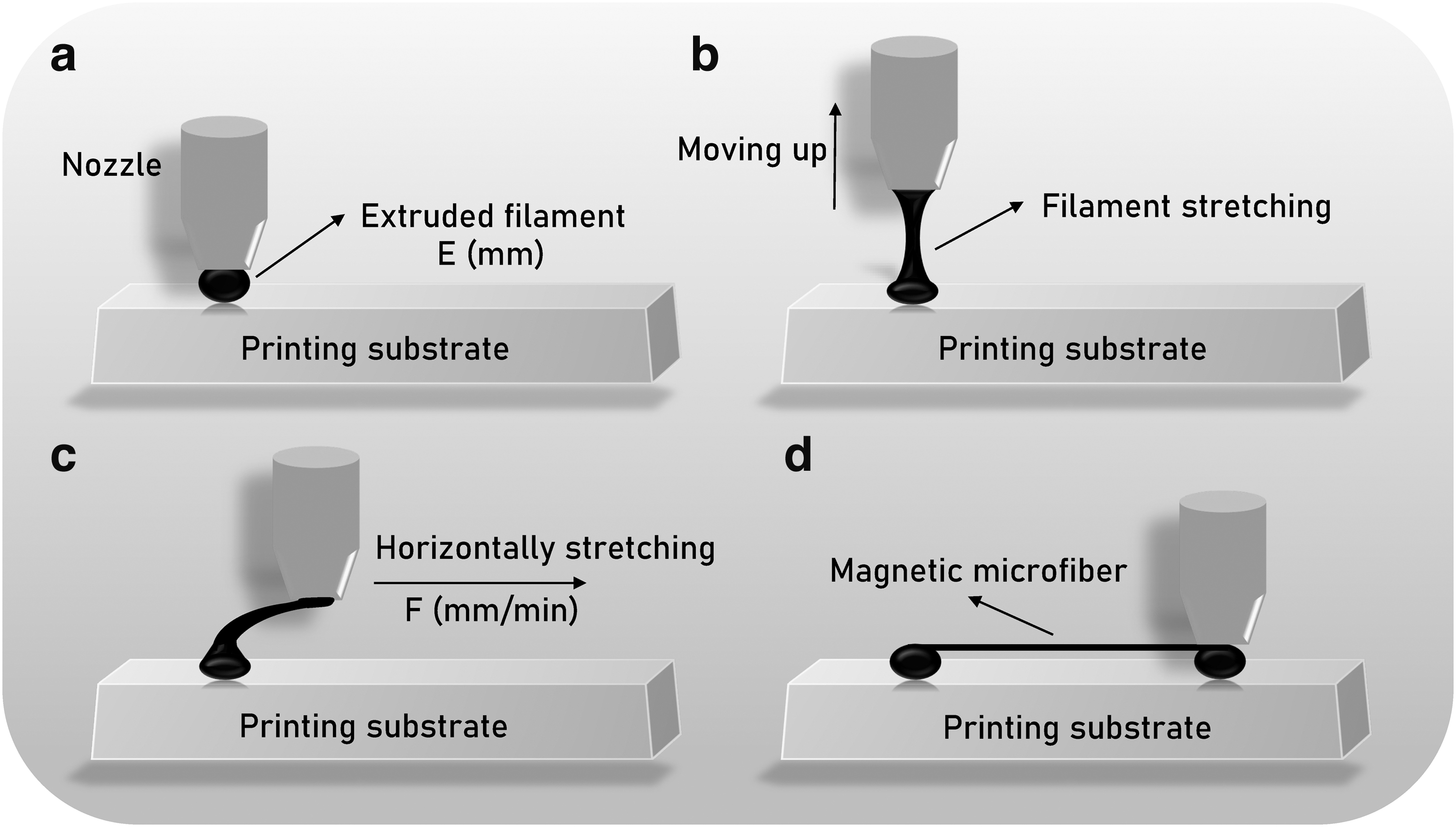
Magnetic microfiber fabrication process with liquid bridge.
First, the nozzle of the printer moved to a certain position on a printing substrate, and the nozzle was adjusted to maintain 0.5 mm gap between the nozzle and the printing substrate. At this time, X, Y, and Z motors stopped the nozzle movement, but a driving motor (filament feeding motor) ran to extrude a certain length of filament to adhere the extruded molten filament on the printing substrate to form a spot (Fig. 1a). Since the spot between the nozzle and the printing substrate exhibited viscoelasticity, while Z motor moved the nozzle vertically upward without further extrusion, the spot was being stretched and thinned to form a string, and necking phenomenon on the stretched string appeared (Fig. 1b). Then, the nozzle moved horizontally, and the necked string was elongated horizontally until the nozzle arrived to the next specified position to reach the required length of a fiber (Fig. 1c). Finally, the nozzle moved vertically downward by 0.5 mm gap on the printing surface, the filament was extruded again to fix the suspended microfibers on the substrate, and a single magnetic microfiber was completely created (Fig. 1d).
In this study, keeping a constant printing temperature, 205°, we controlled two printing parameters, filament feeding length (E) and printing speed (F), to fabricate magnetic microfibers as listed in Table 1 because we discovered in our previous work 32 that those two printing parameters mainly affect fiber thickness. We set E in a range of 0.5–2 mm because it was observed that the produced microfiber diameter became <50 μm when E was <0.5 mm which was smaller than the size of the NdFeB particles, resulting in disruption of fibers with insufficient polymer bonding to the magnetic particles. When E is >2 mm, the diameter of the microfiber exceeded 500 μm, which can be printed by conventional 3D modeling and then slicing. F was set in a range of 500–2000 mm/min, because too slow moving speed causes the molten polymer to stretch unevenly, and 2000 mm/min is generally the maximum speed of the Z-axis movement of a 3D printer.
Magnetic Microfiber Fabrication Parameters
In this study, an FDM 3D printer (CS20; CREASEE) was used to fabricate magnetic microfibers with a nozzle diameter of 0.5 mm and a printing temperature of 205°. Prepare magnetic microfibers under different parameters to measure the diameter. The parameters of the fibers are shown in Table 1. The magnetic microfibers with a length of 2 cm are prepared, and the sample size under each parameter is 24. The diameter of a magnetic fiber was analyzed by measuring mid-portion (16 mm) of the fiber by image processing without 2 mm at both ends because the two ends (spots) had large difference. All images were taken by an inverted microscope (IX53; Olympus) with 1224 × 960 pixels. We adapted Canny edge detection in MATLAB to calculate the diameter of magnetic fibers and to analyze the uniformity.
Characterization of permanently magnetized microfibers
The 3D printed ferromagnetic microfibers were magnetized by an industrial magnetizer (HZ-910-2S; Shanghai Hengtong Magnetic Tech.) under strong magnetic fields generated at ∼900 V for 1 s. The properties of the permanently magnetized microfibers were investigated in two perspectives, magnetic property and mechanical property. The magnetic property of the microfibers was identified by the deflections under various intensities of magnetic fields. Being fixed at one end, the microfiber was placed in vertical position, and the deflections of the microfiber under various magnetic fields were measured by the mixing ratio of NdFeB-PLA content and the length and the thickness of the microfibers.
Keeping a permanent magnet (∼60 mT) at a position, different distances (horizontally) from the permanent magnet were marked for specific magnetic fields (0–30 mT) measured with a digital gauss meter (KT-105; Keout Tech.). Then, the vertically placed magnetized microfibers were located at the marked positions by a motorized stage, and the deflections of the microfiber were examined by optical images, representing the effect of strength of magnetic fields on the microfibers.
Mechanical property of the magnetized microfiber was also analyzed by the deflection of the microfibers. Considering the reaction force from the deflected microfibers, we measured the normal weight induced by the deflected microfiber with an electronic analytical balance (FA1204; CNSHP), and the reaction force was calculated by multiplying the gravitational acceleration (9.8 m/s) to the weight. Initially, the microfiber was placed in horizontal position with a fixed end (forming a cantilever), and a supporting object was fixed on the center of the balance to support the free end of the microfiber. The horizontally placed microfiber was vertically located to be deflected to reach specific deformations as formed by the different magnetic fields. We read the normal weight by the deflected microfiber after 5 s waiting for stable states of the deflection of the microfiber.
We further tested the mechanical properties of the magnetic microfibers by tensile tests. The test method refers to the general method for fiber tensile testing. 38 We glued the 40 mm long magnetic microfiber to the rectangular frame-type clamping device and fixed the clamping device with the magnetic microfiber on the digital force gauge (DS2-500N; AnRETE) along the axis of the magnetic microfiber, and then fixed the clamp. The holding device is cut to achieve the separation of the two fixed ends. Tensile tests of magnetic microfibers were performed at constant speed.
All measurements for the magnetic and mechanical properties were carried out with three specimens of each dimension of the microfiber.
Application of magnetic microfibers for a bionic motion actuator
To prove the advantage and the property of our proposed magnetic microfibers, we applied the microfibers to imitate the flight motion of insect wings and the swimming motion of fish fins, producing undulating and oscillating motions under alternative magnetic fields. On a rigid base bar as the body of insect or fish, permanently magnetized microfibers were attached with thin film for better visualization during the motion. Arrangements of the magnetic microfibers in common and opposite directions induced the directions of moving magnetic microfibers for oscillations and undulations by rotating a permanent magnet.
Results and Discussion
Microstructure of ferromagnetic filaments
The cross-sections of the prepared ferromagnetic filaments at three ratios were examined under SEM as shown in Figure 2. We defined the magnetic filaments as MF30, MF50, and MF70 by the mixing ratios of 30, 50, and 70 wt. % NdFeB particles to PLA particles in the filaments, respectively. It was confirmed that the size of the NdFeB particles was within the range of 30–100 μm, which was smaller than the nozzle (500 μm) of the 3D printer to avoid any blockage, and that the NdFeB particles were uniformly distributed in the filaments. In all the filaments, no major voids or cracks were observed except for sharp cavities by detached NdFeB particles. However, some circular dents were found in the filament, and they were caused by moisture evaporation during the thermal extrusion. The undesirable dents were reduced after multiple drying processes. In MF70, NdFeB particles dominated the cross-section area of the filament, which explained that higher ratios of NdFeB would not form a proper filament for 3D printing as fewer PLA particles were insufficient to bind NdFeB particles.
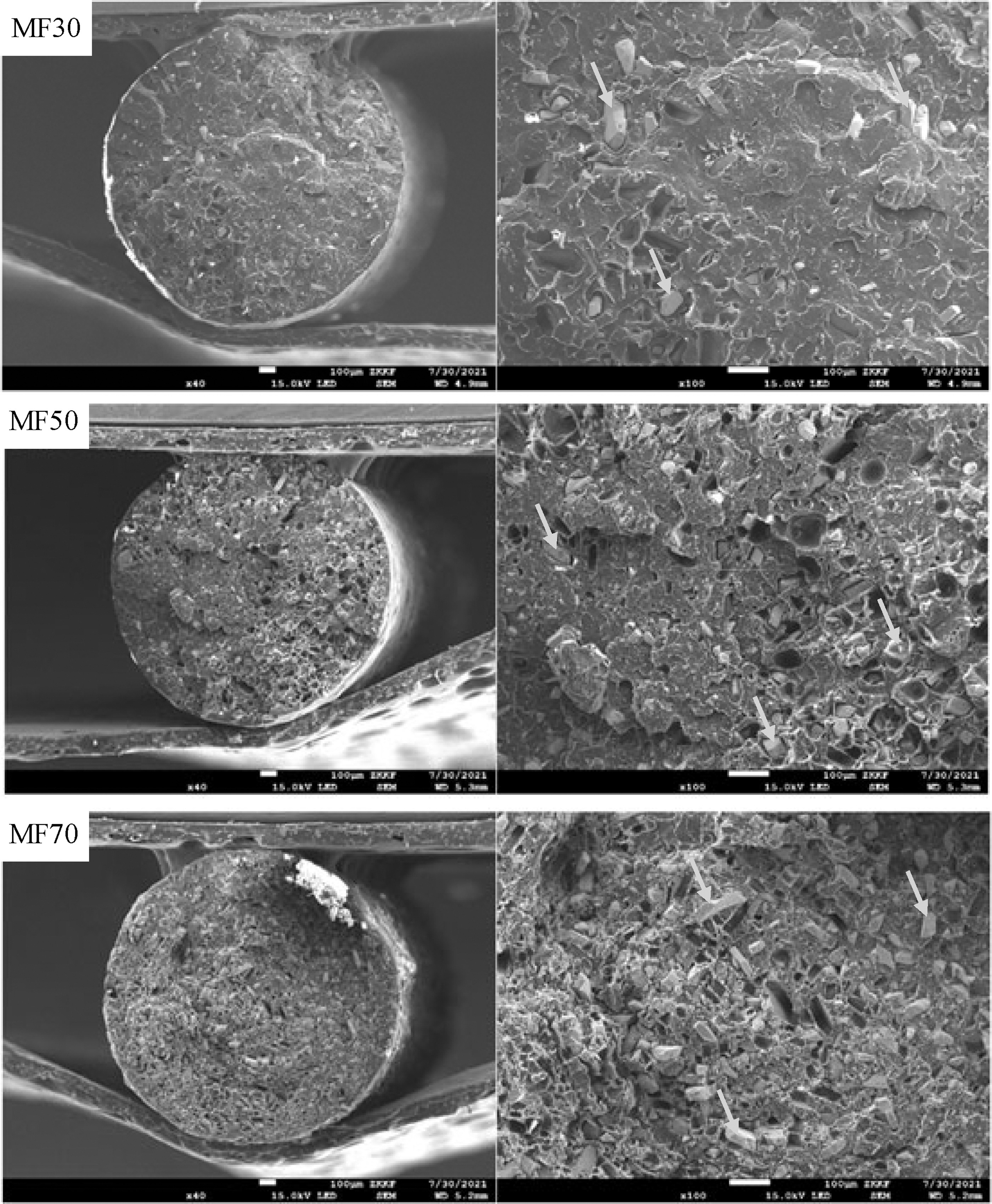
Cross-section SEM images of 30 wt. % (MF30), 50 wt. % (MF50), and 70 wt. % (MF70) NdFeB particles in the filament (left column) and closer views (right column). (The arrows in the closed figure indicate NdFeB particle. Only some NdFeB particles are selected for indication.) NdFeB, neodymium-iron-boron; SEM, scanning electron microscopy.
Magnetic and mechanical properties of the ferromagnetic filaments
We magnetized the prepared magnetic filaments to investigate magnetic qualities (described by a demagnetization curve) of the filaments. The demagnetization curves of the filaments in different ratios are shown in Figure 3. The curve includes values of magnetic field strength (H) in X-axis and magnetic flux density (B) in Y-axis and is consisted of two curves: intrinsic demagnetization curve (J-curve) which reflects the intrinsic magnetic properties of magnetic materials, and normal demagnetization curve (B-curve) which presents the total magnetic flux density under applied magnetic fields.

BH curves of the magnetized filaments at room temperature. The grey arrow represents the intrinsic demagnetization curve (J-curve), and the black arrow indicates the normal demagnetization curve (B-curve).
After being magnetized, a magnet keeps magnetic flux density, and the amount of the magnetic flux density is expressed by residual induction (Br) at H = 0. The crossings of J-curve and B-curve on the X-axis are defined as intrinsic coercivity (Hcj) and coercivity (Hcb), respectively. Hcj indicates complete demagnetization (i.e., magnetic properties of a magnet are lost) of the magnetic material during resisting reversed external magnetic fields. Hcb exhibits remaining magnetic flux density against reverse external magnetic fields, but magnetic properties of a magnet still remain. Maximum energy production (BHmax) explains the capability to store magnetic energy and is found by identifying the largest area of a rectangle under the B-curve.
From our observation, it was found that mainly the mass fraction of NdFeB dominated the magnetic properties. All the properties (i.e., Br, Hcb, Hcj, and BHmax) were increased by the increased ratio of NdFeB particles, which explained that the magnetic fields and the resistance against external magnetic fields of the magnetized filaments increased as NdFeB content ratio was higher. MF70 presented the highest Br of 1.7 kGs by which ferromagnetic materials are easily attracted. Increased Br yielded higher Hcb, inducing highest Hcb of 1.55 kOe and highest BHmax of 5.26 kJ/m3 with MF70. However, Hcj values by different NdFeB particle ratios were very similar because of the same magnetic properties of the material, which explained that regardless of the amount of NdFeB, a similar strength of the magnetic fields was required to completely demagnetize the filaments. The details of the measurement are listed in Table 2.
Magnetic Properties of the Ferromagnetic Filaments
We continued to investigate the mechanical properties, using standard dog bone shaped specimens of the ferromagnetic filaments. The mechanical tensile stress–strain curves of the filaments are shown in Figure 4, and the detailed properties are listed in Table 3. It was clearly seen from the tensile stress–strain curves that the ferromagnetic filaments presented four states during the static tensile process: elasticity, yield, plasticity, and fracture. MF30, MF50, and MF70 were all elastically deformed within ∼0.6% of strain and all yielded ∼1% of strain. Unrecoverable plastic deformation began at ∼1% of strain until fractures occurred at ∼6%.

Stress–strain curves of the ferromagnetic filaments at a strain-rate of 0.001 s−1. The black arrow indicates the fracture of the specimens.
Mechanical Properties of the Ferromagnetic Filaments (Average ± SD)
SD, standard deviation.
Under the elastic region, all the filaments presented similar slopes of the curves, and under the yield region, the specimens underwent a large strain but the stress hardly increases. However, from the plastic region, the three filaments exhibited distinct slopes of the curve, and at the fracture point, the stress and the strain values of the filaments were diverse. The fracture strains of MF30 and MF50 were similar as 7.26% and 7.55%, respectively. MF70 showed the minimum fracture strain of 6.19%. It was because the presence of magnetic particles hindered the chain elongation of the specimen in the direction of the applied load. For the fracture stress, MF30 presented 17.23 MPa, but MF50 and MF70 exhibited relatively larger fracture stresses of 29.01 and 25.33 MPa, respectively.
The elastic modulus of MF30, MF50, and MF70 was calculated from the curves in the elastic region. They were 473, 538, and 596 MPa, respectively, increasing with the amounts of magnetic particles. It was in line with our expectation because of the higher degree of the hardness of the metal magnetic particles in the polymeric matrix. We further performed one-way analysis of variance tests to calculate p-values to investigate the significance among different MFs (i.e., MF30, MF50, and MF70), and all p-values were much <0.05 as listed in Table 3.
It was apparent that adding more metal particles in a polymer matrix resulted in more brittle mixture. Thus, we first conducted a bending test on the ferromagnetic filament to examine the bending fracture angle which is very important for printability because the filament needs to undertake a certain degree of bending (acceptable bending angle less than ∼120°) before being fed to the extruder of a 3D printer. For this test, we prepared four ferromagnetic filament segments, MF30, MF50, MF70, and MF80, and applied loads on the segments.
As shown in Figure 5, the segments presented different bending angles and fracture status. We applied a vertical load on the segments and observed that MF30 made a considerable bending deformation without a fracture, indicating that the dominant polymer (PLA) in the filament accounted for the flexibility. We observed that MF50 and MF70 were broken at a bending angle of ∼120°, which was acceptable for conventional 3D printing process. However, MF80 exhibited extremely brittle property. At the bending angle of 150°, MF80 was disrupted, which was unacceptable as a 3D printing filament. This test agreed to the SEM image in that 70 wt. % of metal particles was almost saturation for bonding in the filament. Therefore, in the further study, we considered the mixing ratio lower than 80 wt. %, using only MF30, MF50, and MF70.
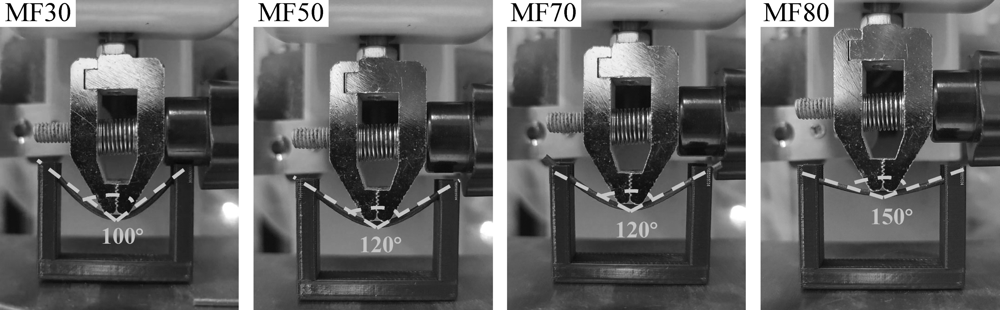
Bending and fracture results of MF30, MF50, MF70, and MF80. All the bending tests at bending angle <120° resulted in fractures of the ferromagnetic filament segments except for MF30.
Rheology properties
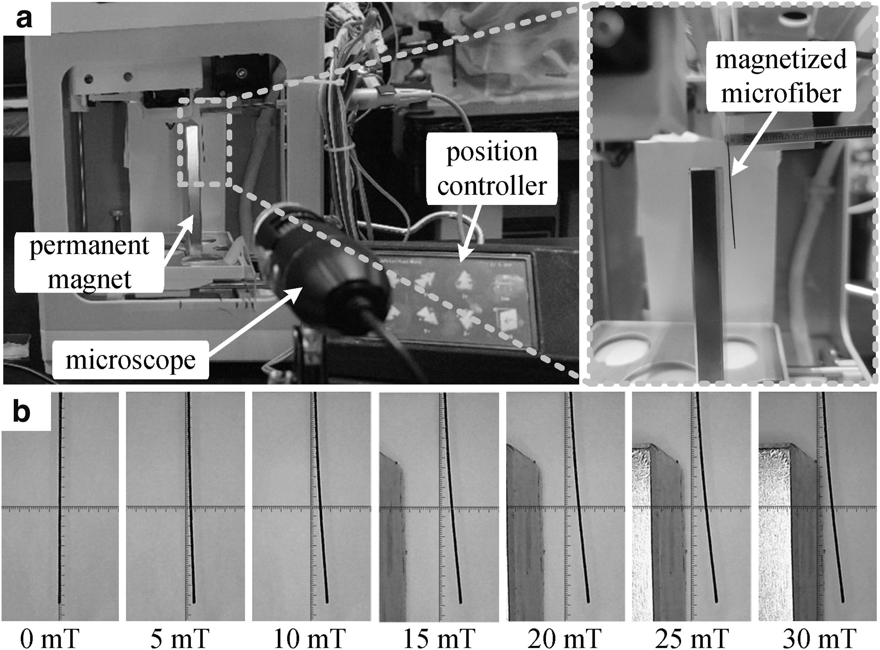
We further investigated the rheology property of the ferromagnetic filament for the 3D printing procedure which includes a thermal melting process of the filament at 205°C (following the standard PLA 3D printing process). Conventionally, the extruding temperature of PLA filament for 3D printing is 205°, and we also applied 205° to print the magnetic filament in this study. Therefore, we only tested the rheological properties of the extruded magnetic filament at 205°. It is well known that the strain of a Newtonian fluid linearly increases by the stress, which means that the viscosity of a Newtonian liquid does not affect the shear rate (i.e., a constant viscosity by shear rate). Our investigation of the molten ferromagnetic filament, however, exhibited nonlinearity between the strain and the shear of the filament melt (in all three ratios) as shown in Figure 6. The graph shows that the viscosity of the filament melts decreases as the shear rate increases, indicating the property of shear thinning of a non-Newtonian fluid and concluding that the molten ferromagnetic filament can be determined as a viscous liquid. The power law equation of a viscous liquid is defined as 39 :
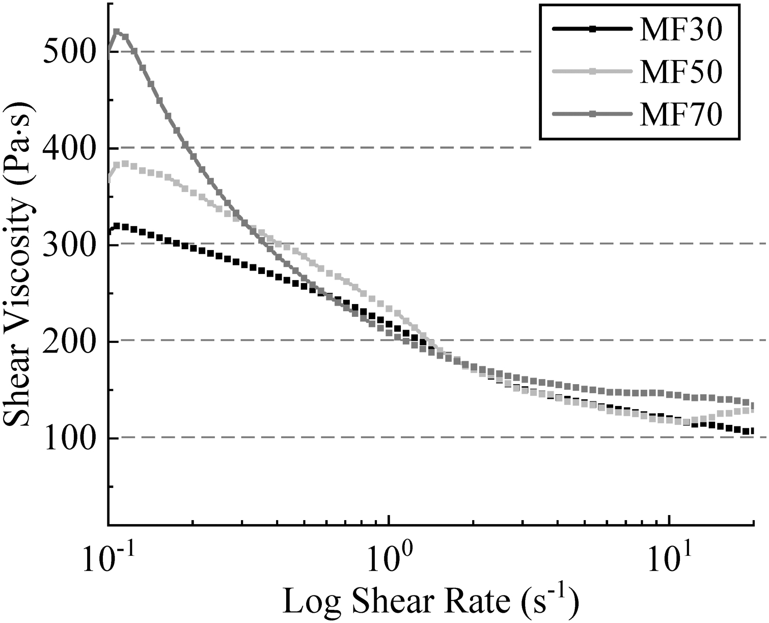
Measured shear viscosities of the molten ferromagnetic filaments at 205°C with respect to the shear rate. After 20 s−1, there is no noticeable change of the shear viscosity.
where τ is the shear stress, t is the time, K is the consistency, n is the flow index, and η is the viscosity. If n > 1, the viscous liquid is called a swelling liquid, confirming that the shear viscosity gradually increases by the increase of the shear rate. If n < 1, the viscous liquid is called a pseudoplastic liquid, presenting gradual decreasing of the shear viscosity by the increase of the shear rate. We made a power function fitting on the viscosity-shear rate curve of the molten ferromagnetic filament and obtained the empirical values of K and n as listed in Table 4.
Rheological Constants of the Molten Ferromagnetic Filaments
In addition, we found that the shear viscosity was quite low after the shear rate of 5 s−1. For the further study of microfiber fabrication, the lower viscosity was challenging to perform filament stretching to form microfibers. Thus, it was necessary for us to apply a lower shear rate (i.e., higher shear viscosity) for microfiber fabrication, and we set the maximum printing speed (F) as 2000 mm/min to achieve a shear rate of 1.7 s−1 for 20 mm microfiber, ensuring proper stretching and forming of microfibers.
Fabrication of ferromagnetic microfibers
Using the prepared ferromagnetic filaments (MF30, MF50, and MF70), 2 cm-long ferromagnetic microfibers were fabricated by controlling filament feeding lengths (Es) and printing speeds (Fs), and the ferromagnetic microfibers are presented in Figure 7. It can be clearly seen that the dimension and the shapes of the microfibers are diverse with various printing parameters.

Optical images of 3D printed ferromagnetic microfibers (2 cm in length) with various printing parameters. A single microfiber was printed from left to right. E is the extrusion amount at the starting point, and F is the speed during the drawing process. 3D, three-dimensional.
In general, with lower Es, a microfiber was formed starting from a Taylor cone after a spot and being stretched to the other end (spot). Obviously, the thickness of the microfiber between the two spots (i.e., ends) was determined by the tip of the Taylor cone. In addition, it was observed that the microfibers at higher Fs included thicker mid-section than the two adjacent sections, especially at E0.5. It was assumed that higher printing speed (F) and acceleration caused a higher shear stress from the gathered molten filament in the nozzle, and the higher shear stress resulted in a separation of small amount of molten filament from the gathered molten filament. Since the thickness of a microfiber became smaller at lower E, the shear stress influenced relatively higher on the smaller affected area, and a separation was made.
The further section of a microfiber was made from the separated molten filament, and the separated molten filament was located at equilibrium by both ends. We experienced that during the printing process at E0.5, microfibers were often disconnected from the adjacent sections, resulting in failures. However, at lower F (i.e., F500), the thickness of the mid-section of a microfiber was not relatively thicker than the two adjacent sections. It was because the shear stress was not relatively high enough to tear some amount of molten filament from the gathered molten filament in the nozzle. At larger extrusion lengths (E > 1), Taylor cones were not obviously observed, and the thickness of the microfibers was more uniform.
From the optical image, it was also apparent that the printing speed (F) had high effects on the thickness of the microfiber. The thickness of the microfiber decreased with the increase of F. This was because the high shear rate induced by higher F made the viscous liquid (i.e., the molten filament) thinner by lowering the viscosity (η), resulting in smaller stretched volume of the molten filament by the viscosity. However, at a certain E, uniformity (the thickness of microfibers) at higher F was lower.
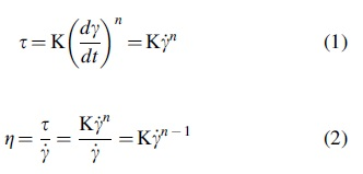
After printing 2 cm-long ferromagnetic microfibers, we investigated the thickness of the microfiber by measuring three specimens for each test, and the results are illustrated as color plots as shown in Figure 8. It was measured that the average maximum thicknesses of the microfibers with MF30, MF50, and MF70 were 439, 449, and 455 μm, respectively. Although the difference was not much, as expected, the higher mixing ratio resulted in the highest thickness because of more metal particles in the filament. In addition, the average minimum thicknesses of the microfibers with MF30, MF50, and MF70 were 122, 76, and 94 μm, respectively. We expected that MF30 would result in the smallest thickness; however, MF50 appeared with the smallest thickness of a microfiber. It was because the hard metal particles in the mixture prevented some excess soft molten PLA in the nozzle from being dismissed, and 50 wt. % of mixing ratio turned out to be an optimal mixing ratio for thin microfiber fabrication.
Mean thickness of the printed ferromagnetic microfibers at various Es and Fs from
Overall, as observed from the results, the thicknesses of the microfibers from the three mixings under the same printing parameters were not very distinctive, although the microfibers from MF70 revealed a slightly more noticeable linearity with the printing parameters, especially in maximum and minimum thicknesses. The result implied that E and F contributed to predict and control the thickness of microfibers plainly as lower E and faster F generated thinner microfibers. However, with the similar Es and Fs, the thicknesses of ferromagnetic microfibers at different MFs were not greatly divergent.
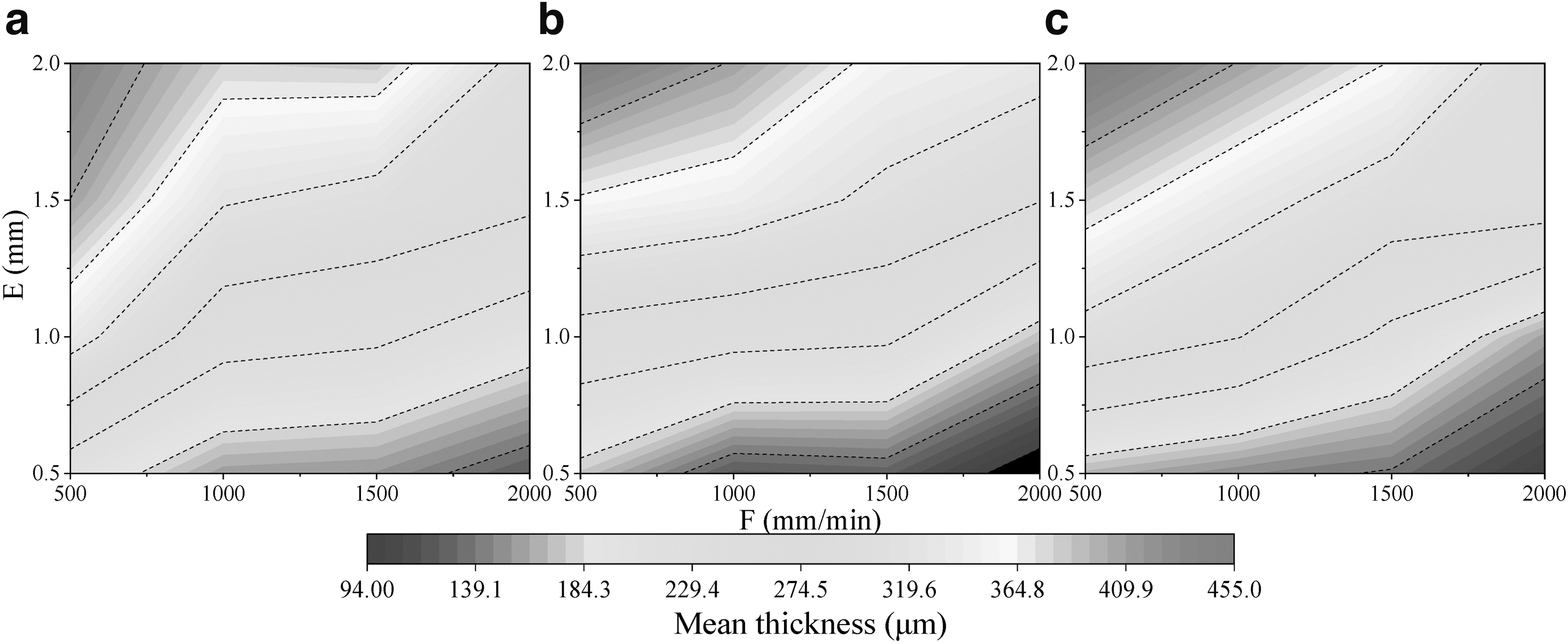
We further calculated coefficient of variance (CV = standard deviation/average) of the thickness to evaluate the uniformity of the printed ferromagnetic microfiber (CV <5% represents a uniformity). The calculation result is illustrated in Figure 9. The minimum CV of the microfiber thickness with MF30, MF50, and MF70 was 7.2% (E2.0 and F500), 10.2% (E2.0 and F1000), and 8.9% (E2.0 and F1000), respectively. It was observed that CV was very large if E was small, representing that the thickness at lower E was uneven. That was because the printing parameters were very sensitive to the thickness with thin microfibers. In addition, from the SEM images of ferromagnetic filaments, the presence and the distribution of larger NdFeB particles (∼100 μm) affected the uniformity of the thickness. More even distribution with smaller NdFeB particle would achieve more uniform thinner ferromagnetic microfibers. However, more uniform microfibers were observed at high Es and low Fs due to wider thickness of the microfibers. This analysis is of guiding significance for the fabrication of uniform microfibers with controllable size.
Uniformity of the thickness of the printed ferromagnetic microfibers at various Es and Fs from
We continued to fabricate longer ferromagnetic microfibers (i.e., 3 cm [L3], 4 cm [L4], and 5 cm [L5] in length) and investigated the mean thickness and the uniformity of them, applying similar Es and Fs of the previous experiments to achieve the demanded lengths with minimal adjustments. The thickness of the longer microfibers is presented in Figure 10 with respect to the ratio of magnetic particles (MF). Furthermore, we printed the longer microfibers with specific thicknesses, 250, 300, and 350 μm. Due to the magnetic particles and the length of the microfibers, smaller thickness was not easily achievable. After the printing, it turned out that the printed microfibers were a bit thicker than the desired thickness. Thus, we classified the thickness of the printed longer ferromagnetic microfibers in three groups, D260 (260 ± 9 μm), D310 (310 ± 8 μm), and D360 (360 ± 8 μm), by averaging the thicknesses.

Mean thickness of the printed ferromagnetic microfibers at various Ls and Ds from
The uniformity of the thickness of the longer microfibers is represented by the CV as shown in Figure 11. The minimum CV of the microfiber thickness with MF30, MF50, and MF70 was 3.6% (L3 and D260), 5.7% (L5 and D360), and 8.0% (L5 and D310), respectively. Overall, MF30 reached CV < ∼10%, MF50 had CV < ∼12%, and MF70 presented CV < ∼16%. It concluded that it was possible to achieve some uniform thickness of the ferromagnetic microfibers with MF30, but with higher magnetic particle ratios (MF50 and MF70); it was difficult to print the thickness of the microfiber in uniform.

Uniformity of the thickness of the printed ferromagnetic microfibers at various Ls and Ds from
The filament stretching method we used successfully fabricated ferromagnetic microfibers which had much smaller diameter than the nozzle size of 3D printer, while conventional 3D printing process generates printed strings in at least the diameter as the nozzle size. The stretching method that is simpler makes the preparation method of magnetic microfibers simpler in that this approach does not require additional auxiliary equipment, and does not require pre- and postprocessing, and can produce high aspect ratio microfibers (from a 500 μm nozzle) with a controllable thickness range. At the same time, the 3D printing preparation method makes the size parameters of the magnetic microfibers controllable. We could obtain magnetic microfibers in different diameters and lengths to meet more needs by setting the preparation parameters, and the length of the printed magnetic microfibers can vary from millimeters to centimeters.
Magnetic and mechanical properties of permanently magnetized microfibers
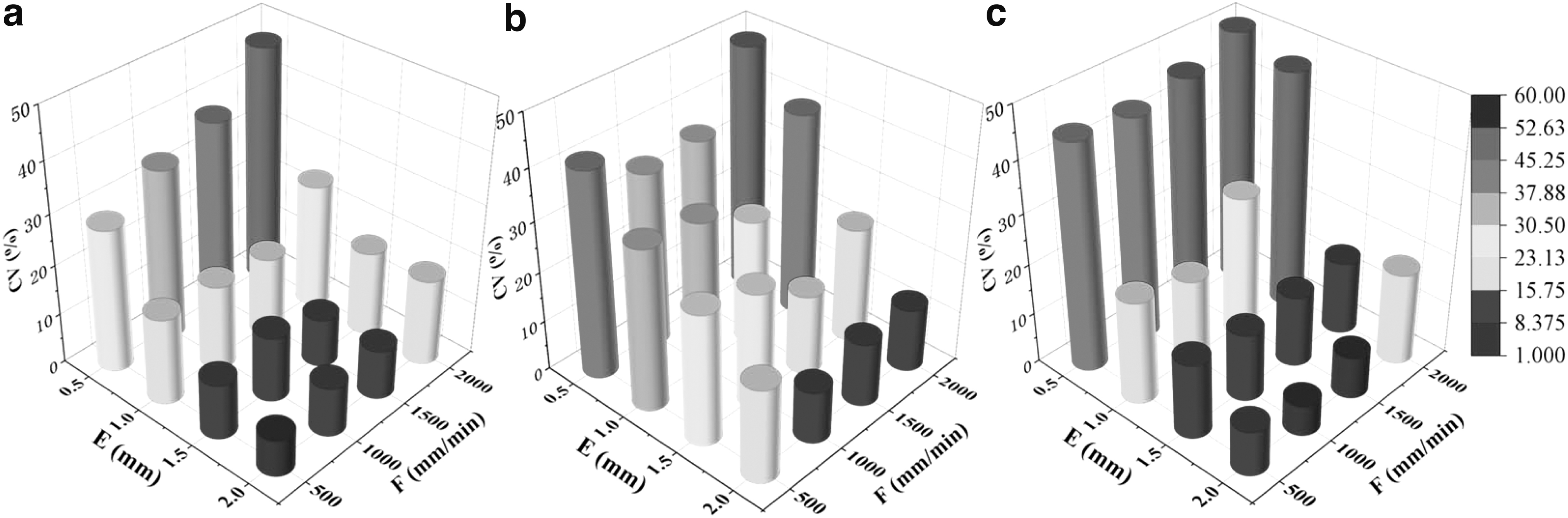
After magnetization of the 3D printed ferromagnetic microfibers, we measured magnetic and mechanical properties of the permanently magnetized microfibers (hereafter, named as “magnetic microfiber”) as described in the preparation section. A magnetic repulsion test of the magnetic microfiber under certain magnetic fields by a permanent magnet is demonstrated in Figure 12a. A vertically placed magnetic microfiber with one fixed end was repulsed by a permanent magnet in various distances where specific magnetic fields were induced by the permanent magnet. We precisely located the permanent magnet by a position controller for 5, 10, 15, 20, 25, and 30 mT. As the magnetic fields increased, it was observed that the deformation of the free end of the magnetic microfiber was greater, and the bending deformation was measured by optical images from a microscope as shown in Figure 12b.
Experiment of magnetic repulsion of the magnetic microfibers:
The bending deformation of the magnetic microfiber was represented by displacement of the free end of the microfiber from the neutral position (the vertical line in Fig. 12b). In this study, we selected three thicknesses for the repulsion test, 260, 310, and 360 mm (mean values), because the uniformity of thinner ones (<260 mm) was not proper for analysis of the repulsion, and thicker ones (>360 mm) required stronger external magnetic fields for more distinctive deformations (which is not easily preparable for applications). For the identification of the thicknesses of the magnetic microfibers, D260, D310, and D360 were included in the names of the test samples, respectively. In addition, we selected three lengths of the magnetic microfibers for the repulsive test, 3, 4, and 5 cm, because shorter ones (<3 cm) were too stiff to be deformed, and longer ones (>5 cm) were too weak (easily broken) to be sustained under higher repulsive forces. For the identification of the lengths of the magnetic microfibers, L3, L4, and L5 were included in the names of test samples, respectively.
The results of the magnetic repulsion of the magnetic microfibers under various magnetic fields are shown in Figure 13 by means (dots) and standard deviations (error bars). Each plot in the Figure 13 exhibits the displacement of the microfiber with different NdFeB ratios, MF30, MF50, and MF70. In general, we observed that as the length of the magnetic microfiber increased, the displacement was greater. The ratio of NdFeB particles was also one of the main factors of the displacement. At each dimension of the microfiber (length and thickness), it was clear to observe the noticeable displacement as higher mixing ratios resulted in more displacements. The maximum displacements of L3, L4, and L5 were ∼10, ∼5, and ∼1.5 mm, respectively, with MF70 and under 30 mT. However, the thickness of the microfiber did not significantly influence the displacement of the microfibers during the repulsive test, although thicker microfibers presented lesser displacements (including the error bars).

Results of the magnetic repulsion tests by varying the mixing ratio, the length, and the thickness of the magnetic microfibers. The dots represent the mean, and the error bars indicate standard deviations.
The mechanical properties of the magnetic microfibers were further identified by reaction force of the microfiber during being bent as described in Figure 14. The downward vertical displacement of the microfibers on the support produced the bending of the microfiber, which induced the reaction force of the microfibers. The value of the reaction force was measured by a high-precision balance and by applying the gravitation acceleration. The vertical displacements were set in the ranges of [0, 10], [0, 7], and [0, 5] mm for L5, L4, and L3 samples, respectively. The different displacements of different lengths were considered because shorter microfibers could not bear higher displacement before a breakage. During the experiment, the displacement was increased by 1 mm. After measuring the reaction forces of the microfibers, the data were studied by means and standard deviations.

Experiment setup for mechanical property (i.e., reaction force) of the magnetic microfibers.
The results of the mechanical properties of the magnet microfibers are presented in Figure 15. Each plot in the Figure 15 exhibits the reaction force of the bent microfiber with different thicknesses of microfibers, D260, D310, and D360. Overall, it was observed that as the length of the magnetic microfiber increased, the reaction force was lower. It was also observed that the ratio of NdFeB particles was also one of the main factors of the reaction force, presenting that higher mixing ratios made higher reaction forces due to the stiffness induced by more metal particles. The maximum reaction forces of L3, L4, and L5 were ∼22, ∼12, and ∼6.5 mN, respectively. In most cases, MF70 and D360 samples exhibited the maximum reaction forces; however, with L3, MF50 and D360 presented the highest reaction force. It was because the microfiber with MF70, D360, and L3 was too brittle to sustain the higher displacement before a breakage.
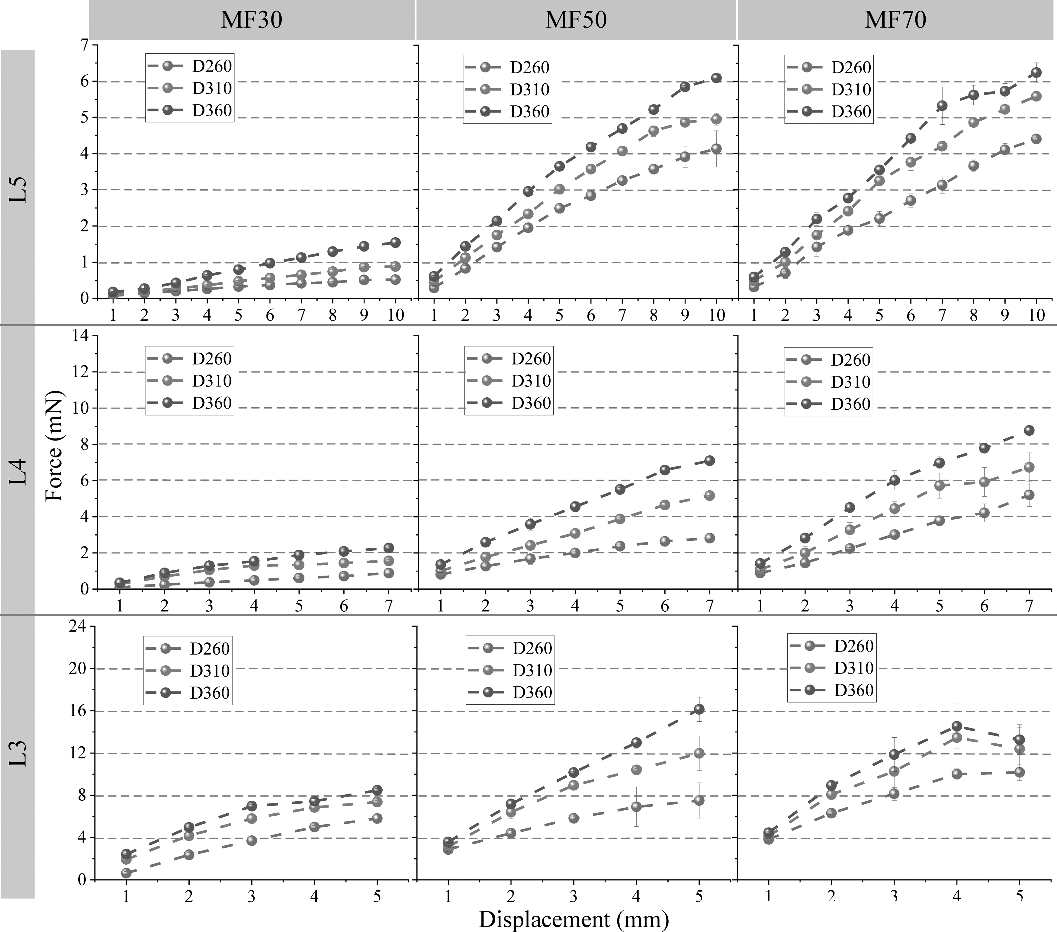
Results of the reaction force tests by varying the mixing ratio, the length, and the thickness of the magnetic microfibers. The dots represent the mean, and the error bars indicate standard deviations.
We continued to investigate maximum bending angle (breaking angle) with the reaction force of the 3D printed magnetic microfibers, and the results are listed in Table 5. The breaking angle was measured as the bending angle measurement of the magnetic filament (Fig. 5); thus, lower angle represents more bending of the microfibers. From the examination, it was observed that more NdFeB particle in the compound presented higher bending (lower breaking angle), and at the same NdFeB ratio, the thicker microfiber exhibited more bending (lower breaking angle). When the microfibers were bent in maximum, the breaking angles were 40°, 115°, and 130° for MF30, MF50, and MF70, respectively.
Maximum Bending of Magnetic Microfibers with Different Mixing Ratios and Thicknesses
We further observed the mechanical properties of the magnetic microfibers through tensile tests. As shown in Figure 16, the distance between the two ends of the clamping device was constant at 30 mm. The tensile tests were performed by different NdFeB particle ratios (MF30, MF50, and MF70) and thickness (D260, D310, and D360).

Experiment setup for mechanical property (i.e., tensile test) of the magnetic microfibers.
The tensile test results of the magnetic microfibers are shown in Figure 17. Overall, we observed that lower NdFeB particle ratios presented higher tensile forces because higher NdFeB particle ratios yielded more brittleness of the microfiber. At the same NdFeB particle ratio, the tensile force increased with the increase of the thickness of the magnetic microfibers. The maximum tensile forces of magnetic microfibers made of MF30, MF50, and MF70 were ∼3.2, ∼1.35, and ∼1 N, respectively. During the tensile test, before breakage, the elongation of the magnetic microfibers made of MF30, MF50, and MF70 was ∼2.2, ∼1.1, and ∼0.4 mm, respectively, which also indicated that the magnetic microfibers became less elastic by the increase of NdFeB particles.
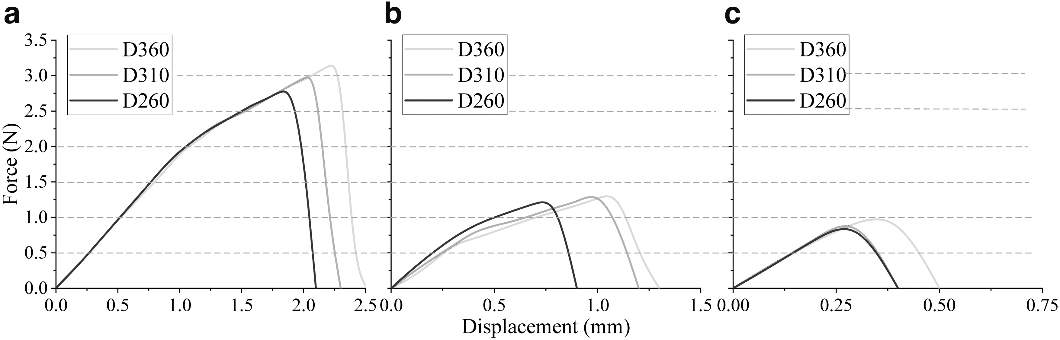
Tensile force of the magnetic microfibers in different thickness from
In consideration of 4D printing with the magnetic microfibers, the microfiber should include higher magnetic attraction and repulsion with less stiffness. Our observation from the experiment disposed optimal parameters for 3D printing of magnetic microfibers for 4D printing. Considering that conventional external magnetic fields for 4D printing are about 30 mT (it is limited by the distance) by a permanent magnet, the magnetic microfiber should generate more magnetic fields for magnetic attraction and repulsion and should be more flexible for desired deformations effortlessly. From this study, we confirm that higher flexibility and greater magnetic property of magnetic microfibers are achieved by longer lengths, thicker thickness, and higher ratios of ferromagnetic materials, and the values are L5, D360, and MF50. Although MF70 presents a higher magnetic property than MF50, the mechanical property of MF70 is feeble (especially, fragile). Thus, MF50 is more suitable for 4D printing as a motion actuator. We further briefly present an application of the proposed magnetic microfibers with L5, D360, and MF50.
Application
In this study, we briefly introduce an application of our proposed magnetic microfibers for bionic motion actuator. The magnetic and mechanical properties of the magnetic microfibers can provide unique movements, such as in-phase and out-of-phase actuations. Recently, bionics of tiny insects and animals have received great attention to learn the insights of the nature for improvement and development of tools and devices. A dragonfly can fly in all directions with its four light wings forming different phase angles between forewings and hindwings depending on flight modes,40,41 which is very attractive to design flight vehicles. A fish can control its locomotion by its wavy fins with various frequencies, and the movement of fish fins has been studied based on undulatory motion versus oscillatory motion.42,43 However, traditional mechanical actuators have gradually lost their advantages in miniaturization and lightweight for tiny bionic insects and animals.
Our proposed magnetic microfibers are thin (<0.5 mm in diameter) for microsized structures and possess magnetic polarity for actuation. The distinguished properties of the microfiber conveyed a lightweight bionic motion actuator, such as insect wings and fish fins, as shown in Figure 18. The actuators by MF50D360L5 magnetic microfibers were controlled in-phase or out-of-phase through the changes of external magnetic fields, and desired movements were achieved with the arrays of the opposite magnetic polarities for undulation (out-of-phase motion patterns, see Fig. 18a–c) and the same magnetic polarity for oscillation (in-phase motion patterns, see Fig. 18d–f). Underneath the magnetic microfibers, alternating magnetic fields of ∼20 mT were produced from a rotating permanent magnet. By the external magnetic fields, the free ends with the same magnetic polarity were displaced upward by ∼1 cm, which was caused by the gravity and the decreased strength of magnetic fields by the distance from the magnetic field source, while the free ends with the opposite polarity were attracted downward by ∼3 cm.

The schematics of bionic motion actuators by the magnetic microfibers (left) and the optical images of the desired movements, undulation
We further maneuvered diverse actuation modes of the magnetic microfibers by varying the angles of the microfibers to the magnet. The angles between the microfiber and the magnet yielded different strengths of magnetic fields to individual microfibers. We set four angles (0°, 15°, 30°, and 45°) between the microfibers and the magnet and observed the deformation of the microfibers. The results of the actuating deformation are shown in Figure 19, and the motions of the deformations are presented in the Supplementary Videos S1–S4. As the angle increased, the varying deformation of the magnetic microfiber became more obvious: microfibers farther from the magnet were less deformed, while microfibers closer to the magnet were more deformed. Thus, we were able to achieve distinct actuations of undulation and oscillation of the magnetic microfibers. It was observed that the free ends of the microfibers were repelled or attracted by 0–4 cm.
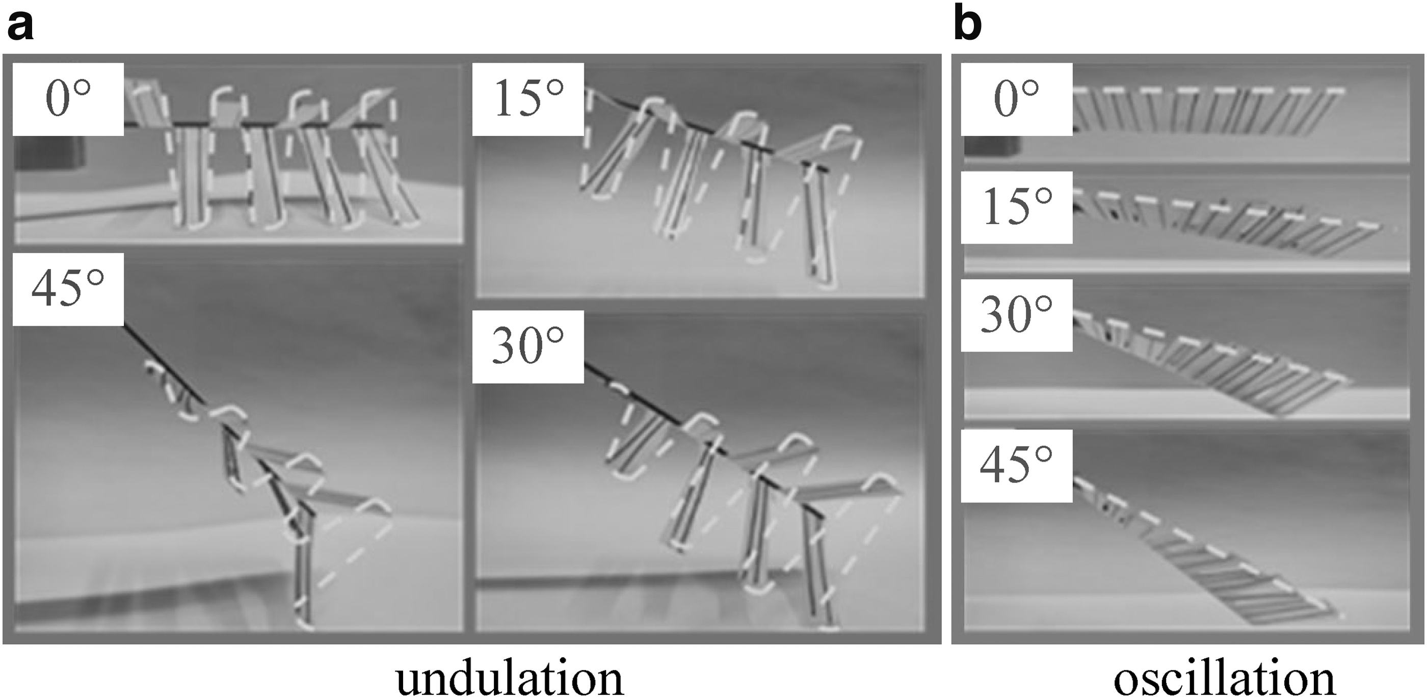
Various actuating deformations of the magnetic microfibers for
The proposed magnetic microfiber provides both lightweight and various actuation modes. From the experiment, it is clear that the magnetic microfibers are feasible to mimic the actuation modes of fish fins and/or insect wings. In particular, the combination of magnetic microfibers and flexible bodies (represented as the angles in the experiment) can boost the deformation modes, which can be widely found in the small biological beings.
Conclusion
This study introduced a novel fabrication of magnetic microfibers by filament stretching 3D printing method. We prepared NdFeB-doped polymer filaments for FDM printing and characterize its mechanical, magnetic, rheological properties and microstructure and used the filaments to print ferromagnetic microfibers in various thicknesses (76–455 μm) and lengths (2–5 cm) by a nozzle of 500 μm. It was very difficult to meet the uniformity of the printed ferromagnetic microfibers due to the size of the magnetic particles in the prepared filaments. However, more uniform ferromagnetic microfibers were achieved at high filament extrusions and low printing speeds due to wider thickness of the microfibers.
After magnetization, magnetic microfibers were completed, and the magnetic and mechanical properties of the magnetic microfibers were investigated for 4D printing. The magnetic microfiber presented various deformation modes under external magnetic fields. It was observed that the maximum displacements of 5 cm-long, 4 cm-long, and 3 cm-long magnetic microfibers were ∼10, ∼5, and ∼1.6 mm, respectively. Shorter magnetic microfibers (<3 cm) were too stiff to be deformed, and longer magnetic microfibers (>5 cm) were too fragile to support mechanical loads. The results of various deformation modes represented a high potential of the magnetic microfiber for 4D printing.
We further briefly applied the magnetic microfiber for bionic motion actuators, achieving undulation and oscillation modes. Under alternating magnetic fields, the arrangement of the magnetic microfibers by the opposite polarity generated the undulation mode, and the arrangement by the same polarity yielded the oscillation mode. Moreover, the angles of the microfibers to the external magnetic fields promoted the actuating deformation modes of undulation and oscillation by fluctuating amplitudes of individual magnetic microfibers, which are common in the tiny biological insects and animals.
We continue to investigate the magnetic microfiber for flexible bodies (i.e., soft robotics) to improve and develop actuations of soft bionics.
Footnotes
Authors' Contributions
Y.H.: Writing—original draft; experiment; data curation. Q.L.: Experiment; methodology. J.X.: Resources. K.-Y.S.: Funding acquisition; supervision; review; and editing. D.L.: Resources.
Author Disclosure Statement
The authors declare no conflicts of interest.
Funding Information
This work was supported by grants from Beijing Institute of Technology Research Fund Program for Young Scholars (grant number 3020012222017).
References
Supplementary Material
Please find the following supplemental material available below.
For Open Access articles published under a Creative Commons License, all supplemental material carries the same license as the article it is associated with.
For non-Open Access articles published, all supplemental material carries a non-exclusive license, and permission requests for re-use of supplemental material or any part of supplemental material shall be sent directly to the copyright owner as specified in the copyright notice associated with the article.