
Abstract
Multimaterial additive manufacturing is expanding the design space realizable with 3D printing, yet is largely constrained to sequential deposition of each individual material. The ability to coextrude two materials and change the ratio of materials while printing would enable custom-tailored polymer composites. Here, the evolution of a dynamic material coextrusion process for additive manufacturing capable of printing any ratio between and including two neat input materials is described across 3 hot-end generations and 14 implemented design iterations. The designs evolved with increased understanding of manufacturing constraints associated with the additive manufacturing of metal components with internal flow bore diameters on the order of 2 mm and typical bore length around 50 mm. The second generation overcame this issue by partitioning the design into two pieces to locate the flow channel geometry at the interface between the components so that the details could be easily printed on the components' external surfaces. The third concept generation then focused on minimizing flow channel volume to reduce the average length when transitioning between materials by 92%. The third-generation design was also used to investigate the improvements in dimensional stability during annealing of acrylonitrile butadiene styrene (ABS) made possible by coextruding ABS with a polycarbonate (PC) core. The standard deviation of part shrinkage after annealing was 7.08% for the neat ABS but reduced to 0.24% for the coextruded ABS/PC components.
Introduction
Additive manufacturing by material extrusion (e.g., fused filament fabrication [FFF] or fused deposition modeling [FDM™], direct ink writing, ambient reactive extrusion) is a layer-by-layer method of depositing material to create a final product. 1 Material extrusion provides a wide range of processing settings such as layer heights, road widths, and print rates. 2 Material extrusion can print multiple materials, typically by using individual extruders for each material.3,4 In this typical approach, an extruder is enabled when the corresponding material is to be deposited, while the secondary extruder remains idle and vice versa.
In FFF, coextrusion through a single hot end is an alternative to multiple extrusion heads that could both reduce time and material waste as well as enable improved part properties. Demonstrations of coextrusion include extrusion of multimaterial filaments to achieve high-impact acrylonitrile butadiene styrene (ABS)-polycarbonate (PC) components through annealing.5,6 In this work, Wetzel et al. created filament with a coextrusion die containing an ABS shell and a PC core, which was then loaded into a traditional FFF printer to manufacture parts that are subsequently annealed. The higher glass transition temperature of PC allowed for printed products to be annealed at temperatures above the glass transition temperatures of ABS such that the annealed products had impact properties similar to those of molded ABS. While this process is effective, it requires an additional step to manufacture the filament, and the material ratio of shell to core is determined during the coextrusion stage and remains constant during the printing stage, not allowing for dynamic tailoring of material ratios within a single print.
Other related work includes Peng's manufacture of polyethylene shell–core filament that has three times higher strength than virgin polyethylene. 7 In this study, Peng et al. used two extruders with gear pumps to coextrude and align filament to be processed for use with an FFF printer. The material ratio could be changed throughout the filament spool by utilizing individual melt pumps during the filament extrusion process. Although this method provides the ability to dynamically alter the filament, accurate estimation of where the material will be along the spool would be required to match the composition with the desired deposition location in the part. Khondoker has also demonstrated metal core–polymer shell coextrusion 8 and bimaterial dual extrusion.9–11
Whereas the previous methods of Wetzel and Peng were demonstrated exclusively with thermoplastic materials, Khondoker's system is capable of extruding both metal and elastomeric materials. These materials were enabled by the addition of a syringe pump and pellet extruder to the printer system. Khondoker bimaterial system utilized a single hot end that extruded two different materials simultaneously, resulting in an extrudate that comprised two materials side by side. The relatively simple design allowed for integration onto a 3D printer without the need for large modifications, but with limited thermal and flow control.
This article describes a new approach to additive material extrusion, referred to as fused deposition manufacturing of multiple materials (FD3M). FD3M intakes two materials and combines the melt flows into a single shell–core flow before exiting through a single nozzle. The two primary objectives are: first, to use a flow manifold and a single nozzle to decrease the time to switch between materials; and second, to dispense varying composite fractions to increase the functionality of the FFF extrusion technique. The article presents the iterative design of the FD3M hot end, the analysis of flow and transient deposition, and finally performance of the developed system.
Printhead Design Process
Initial design with opposing fluid ports
The initial design concept was inspired by a multiport hydraulic spool valve in which opposing fluid ports balance the forces across the spool to reduce actuation forces. The initial design (shown in Fig. 1a) incorporated two arms that interfaced with E3D Titan extruders (Chalgrove, UK) to deliver flow to different layers of the manifold.

Section views of coextrusion manifold designs, including
The central valve pin had a 10 mm outer diameter, 2 mm bores, and was able to use standard M6 threaded nozzles, to allow for the investigation of different outlet diameters. The valve pin was mated with the central bore of the manifold with a diametrical clearance of 10 μm to avoid leakage. Specifically, the center valve pin and corresponding bore were designed steel safe and postprocessed by machining. Then, the center valve pin was designed oversized and turned using a lathe while the manifold bore was designed undersized and then drilled and reamed. Each level of the manifold was independently heated using two heater cartridges based on temperature measurements from centrally located thermistor, allowing for each level to operate at different temperatures. Thermal isolation between the two levels was provided through thin ribs at either end of the manifold.
Thermal FEA modeling was performed to confirm that two heater cartridges would provide enough heating to the hot end. Both the valve pin and manifold were manufactured out of 420 stainless steel powder infused with bronze through the method of binger jetting. Additive manufacturing methods such as direct metal laser sintering and lost wax casting through additive manufacturing methods were also investigated. 12
The printhead design iterations discussed in this article were designed in accordance to published “design for manufacturing” guidelines. 13 Design guidelines for binder jetting components suggests a minimum wall thickness and minimum flow bores of 1 mm. 13 Structural integrity of the printed components was never an issue across dozens of received components. However, even with flow bores of 2 mm in diameter, components with a 2 mm bore were often clogged with uncleaned support powder, which became solid after the sintering process. These clogs occurred in both the manifold and valve pin and could not always be corrected with machining given the curved geometry of the flow channels in the manifold and valve pin.
In retrospect, a few successful prints early in the project belied the difficulty of printing and costly development delays that were to come. Tension always exists between design for manufacturability (which emphasizes design simplicity and robustness) and design for assembly (which emphasized minimizing the number of components at the expense of increased design complexity). Of the two, design for manufacturability was the dominating constraint in the development of FD3M. The design of Figure 1a was actually the 3rd design iteration in which clogs in the feed arms and manifolds were being mitigated by separating the arms from the manifold to increase the odds of reduced clogs in the arms and manifold as well as likely success of corrective machining.
Iteration 6 (Fig. 1b) was also implemented with E3D Titan extruders, which slide into the slots at the top of the inlet arms. An active cooling system was added around the passive cooling fins on the inlet arms to minimize heat creep from the main manifold body into the inlet arms and extruders. Without active cooling, backflow of the polymer occurred, causing blockages of cooled polymer within the inlet arms, and halting the feed of the material. After implementation of the active cooling material blockages no longer occurred in the inlet arms. Iteration 6 was tested on a static (nonmoving) stage to explore the coextrusion of varying cross-sections, including core–shell, triclover core–shell, static mixer, and biased cores. Examples of the coextruded cross-sections are presented in the results sections.
Second-generation design using spiral flow manifold
Following the conceptual feasibility testing of the static hot end, the objective was to provide a functional printer that implemented the FD3M method based on two design principles. The first principle was that the valve pin was unnecessary given the low flow rates that are associated with FFF 3D printing. Specifically, it was reorganized that the extruders were capable of independently controlling the volumetric flow rate of each material entering the hot end such that proportional metering with a rotatable valve (akin to the inspiring hydraulic spool valve) was not necessary. The second design principle was that the manufacturability constraints from the metal additive manufacturing process dictate minimization and simplification of internal flow geometries. To alleviate the manufacturing constraints and to allow for easier support powder removal, the flow geometries within the manifolds were moved to the outer surfaces.
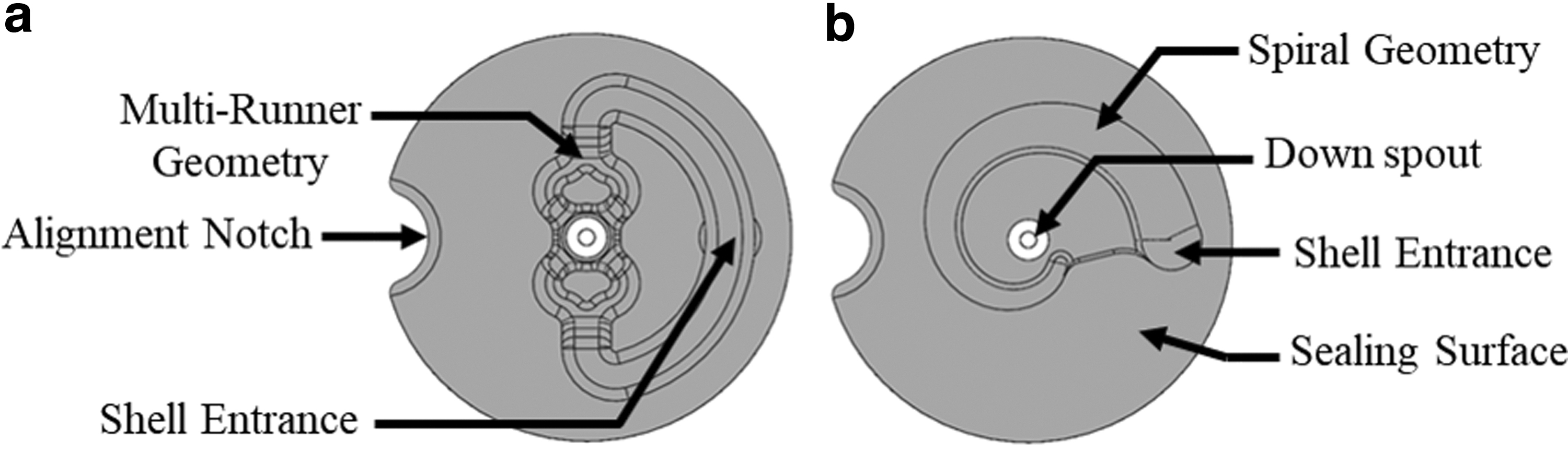
Using these design principles, the central valve pin was replaced with a spiral flow manifold to enable axisymmetric flow as shown in Figure 1c. To ensure manufacturability, the manifold was split into two components, comprising a spiral flow bore and a conical mandrel. The top level of the manifold carried the core material into the lower manifold that contains the spiral flow geometry. The spiral flow geometry allows for the shell material to flow around and down the core material as it enters the lower manifold. The upper manifold also has an air gap to provide thermal isolation from the lower manifold. The two manifolds were made manufactured using binder jetting and 420 stainless steel powder infused with bronze. The two manifolds are bolted together, creating a sealing surface along the top of the lower manifold.
The manifold in Figure 1c utilized coupling nuts to connect the manifold to the material extruders. The coupling nuts initially had one side with an M6 internal thread that the extruder screwed into and one side with an M10 internal thread that secured the manifold inlet. Proper alignment during the threading process was found to be excessively difficult. The design was changed so that both ends of the coupling nut had an M6 thread to allow for the heat break on the extruder to sit against the manifold. This change did not allow for orientation control when tightening, but it was determined that the extruders could be mounted at an angle without adversely affecting performance.
The spiral flow manifold design was successfully implemented across four iterations, with three being fully implemented onto a modified Creality CR-10 V2. Modifications to the CR-10 included incorporation of two E3D Hemera extruders, the custom hot end, and upgraded controls (Azteed X3; Panacutt Devices, Irvine, CA) based on Marlin 2.0.
Third-generation design with interchangeable flow geometries into nozzle tip
The results from the implementation of the spiral flow geometry indicated that the material transition time shown was not sufficiently rapid enough for the FD3M printing process. The shorter the material transition time, the more capable the hot end will be at printing different materials within a single printed component. Using MATLAB image processing (Mathworks, Cambridge, MA), analysis to analyze the hue color value along the deposited road began by superimposing the print path onto the photo of the print, for which the hue is then analyzed along the superimposed path and plotted. The previous design iterations were based off the assumption that the transition time would be solely dependent on the volume of the flow channels where the two materials are combined. However, validation work suggests that the compressibility and/or pressure drop within the hot end could cause backflow of one material into the incorrect flow channel. The recognition of backflow meant that minimization of the volume of the entire polymer feed system became a primary design consideration.
Accordingly, a third and final generation of design incorporated the flow geometry onto the surface of the nozzle tip as shown in Figure 1d. This hot end implements all the insights gained from previous iterations: (1) a modular nozzle die that allows for the investigation of different flow geometries without the need of reprinting a new inlet manifold, (2) the complex flow geometries have been moved to the surface of the nozzle die to allow for easier manufacturing and inspection, (3) a single axial sealing surface between the nozzle and the manifold, (4) straight manifold flow bores allow for easier finish machining and minimized flow length, (5) concentric nozzle die bore allows micromachining of outlet diameter, and (6) two heater cartridges sandwich the flow bores to supply uniform heating.
In the final design of Figure 1d, multiple nozzles have been developed to investigate axisymmetric flow behavior for different materials (shear thinning viscosity properties) and processing conditions (temperature and flow rates). Two different flow geometries a multirunner design and a spiral flow design have been designed as shown in Figure 2. The multirunner geometry has a primary and secondary runner that bifurcates the flow fronts at each split to allow for the shell to wrap around the core material. The spiral flow geometry (Fig. 2b) uses a spiral flow path to guide the shell material around the core such that the rate of pressure drop along the arc length of the spiral equals the rate of pressure drop from the spiral to the central nozzle bore. The nozzles were manufactured from bronze using wax 3D printing and lost wax casting. The manifold and fixing plate were manufactured from 420 stainless steel using binder jet additive manufacturing.
Die geometries for interchangeable nozzle in third-generation design in Figure 1d.
Flow simulation
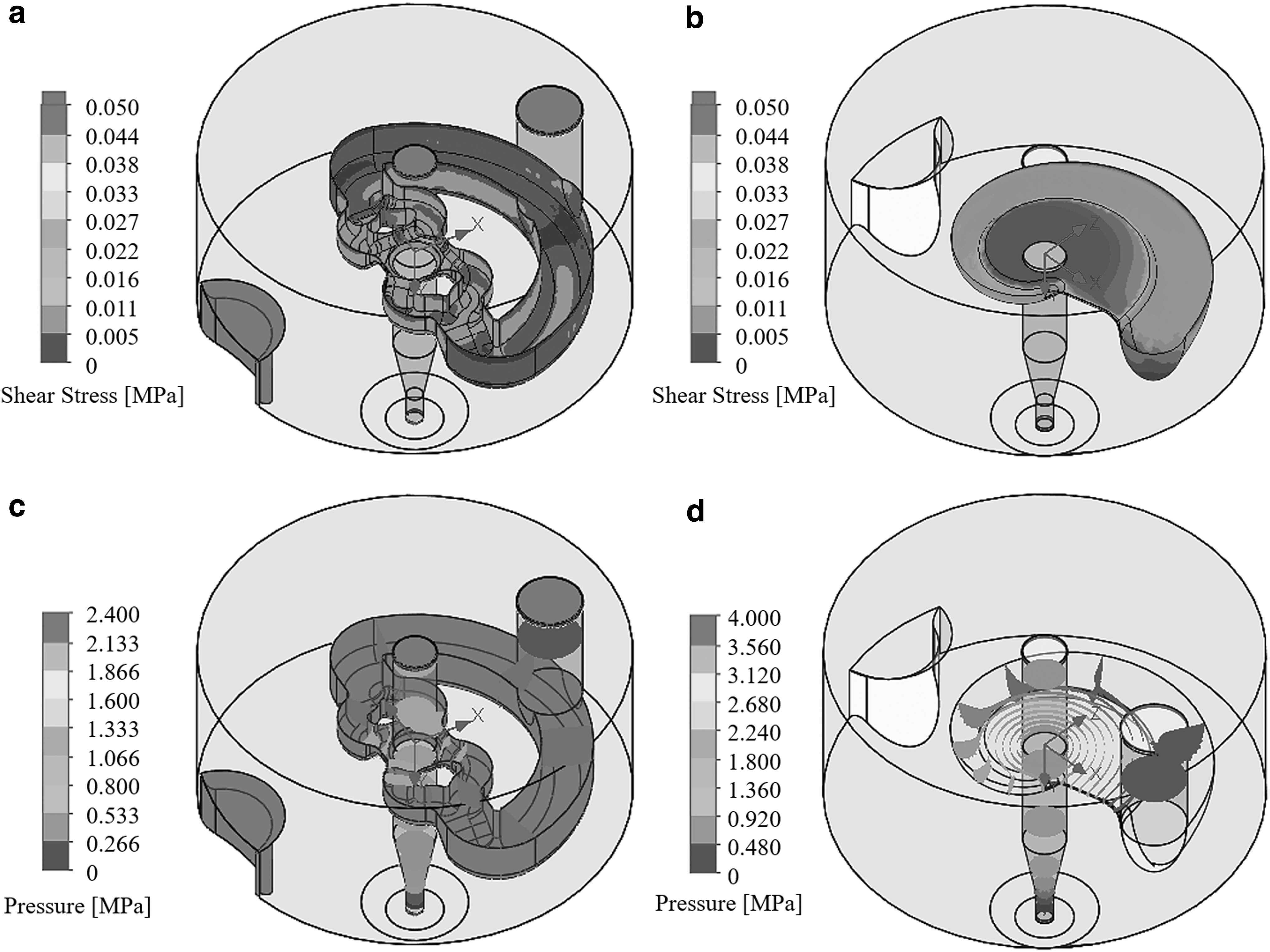
Flow simulations were performed on the two nozzle die concepts to investigate two important factors: (1) the shear stress along the wall and (2) the pressure drop within the flow paths. The simulations were performed with SolidWorks' Flow (Waltham, MA) for an ABS material fed equally at both inlets with a temperature condition of 220°C and a combined volumetric flow rate of 5 mm3/s. Table 1 provides the processing conditions and material properties used for the simulations. A larger shear stress along the flow bore walls assists the polymer delamination from the flow channel surface during material changeovers, thus resulting in a faster material transition time. 14 With increased wall shear stresses, however, comes a larger pressure drop within the system. The goal is to have a maximum pressure drop of 10 MPa to avoid difficulty driving the material through the hot end with the extruders. 15
Simulation Conditions and Parameters
ABS, acrylonitrile butadiene styrene.
Printhead Validation
Sections under steady-state conditions
The simulation results for steady-state shear stress and melt pressure are presented in Figure 3. Referencing Figure 3, the shear stress along the wall for the multirunner nozzle is considerably lower than for the spiral flow. The largest shear stress in both dies occurs near the central bore such that the polymer will more easily pull off the wall near the center of the flow. Meanwhile, the pressure drop results indicate that the pressure around the outlet is balanced, corresponding to an axisymmetric flow at the intersection of the two materials. The spiral flow geometry is highly axisymmetric while the multirunner design suggests the possibility of some lack of concentricity.
Wall shear stresses for the
The extruded sections' profile for steady-state conditions was tested for each of the design generations and for a variety of materials, including ABS (acrylonitrile butadiene styrene), PA (nylon), PLA (polylactic acid), PC (polycarbonate), TPE (thermoplastic elastomer), TPU (thermoplastic polyurethane), and others. Figure 4 provides a set of cross-sections for the first generation of designs (e.g., Fig. 1c) on a static stand for a 50% shell/50% core blend of ABS/PC. The section of Figure 4a indicates reasonable concentricity of the core material within the shell. The clover section of Figure 4b showed that multiple flow outlets could be provided on the pin nozzle to provide lobes to interlock the core and shell materials. The 8-stage static mixer of Figure 4c failed to provide dispersion of ABS within the PC, but resulted in an interesting lamellar structure with layers on the order of 0.1 mm. Lastly, the biased center pin of Figure 4d showed the ability to procure crescent moon shapes in other materials such as PA/TPE.

Extrudate cross-sections produced from design iteration 6 (Fig. 1b).
23
The cross-sections of roads for the third-generation nozzle design (Fig. 1d) with the multirunner design (Fig. 2a) are shown in Figure 5 for varying mixtures of ABS/PC. Generally, the multirunner design produced circular extrudates with a rounded square core. The shape of the core is due to the bifurcating nature of the multirunner flow, in which four flows recombine near the central bore. There is a small pressure gradient around the circumference of the inner bore such that more of the shell material is admitted into the center bore, which results in the inward deflection of the core material and the formation of the square-shaped core. The measured material ratios of the extrudate cross-sections are presented in Table 2.
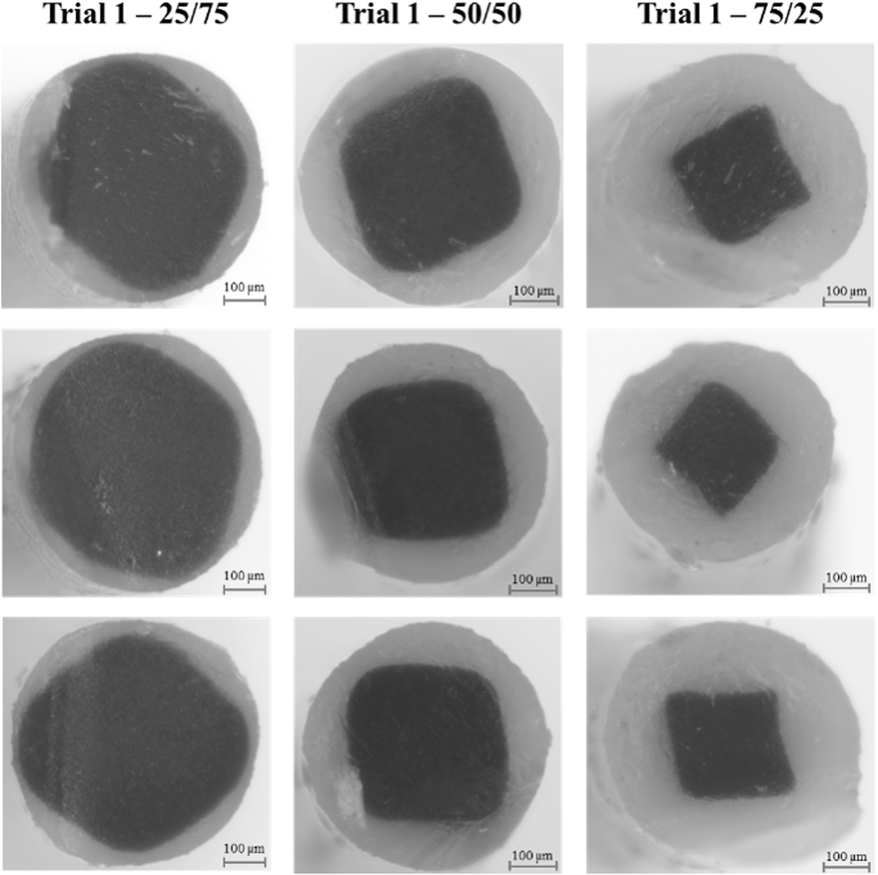
Cross-sections for a single trial of each material ratio. The green shell material is MatterHackers ABS and the black core is Raise3D PC (S8). All ratios are core–shell. The trials were conducted using the third-generation hot end (Fig. 1d). ABS, acrylonitrile butadiene styrene; PC, polycarbonate.
Measured Cross-Sectional Material Composition for Each Trial
Three material ratios were tested: 25% shell/75% core, 50% shell/50% core, and 75% shell/25% core.
Dynamic material transitions
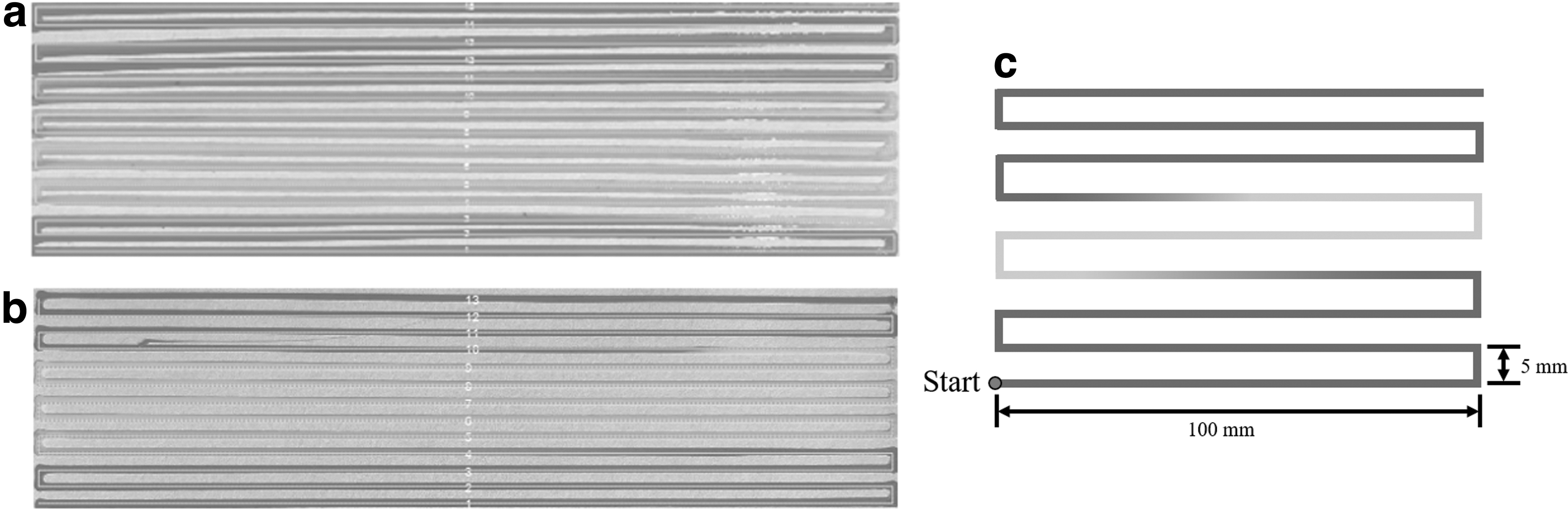
The switchover timescale during dynamic transitions from one material to a second material were tested. Specifically, the serpentine pattern in Figure 6 was printed to evaluate the material ratio controllability, characterize the concentricity of the deposited roads, and to view the transient behavior when printed at different volumetric flow rates. This method of analysis has been performed by Big Areas Additive Manufacturing (BAAM).16,17 The serpentine patterns were printed using two different colors of PLA (blue and yellow) as shown in Figure 6 using the second and third-generation printhead designs of Figure 1c (top) and Figure 1d (bottom), respectively.
Serpentine test print pattern
The color transition time was determined by analyzing the hue color value along the deposited road. The hue, saturation, and value (HSV) plot of the deposited road is shown in Figure 7. The hue value is the color inspection portion of HSV, which expresses a number from 0 to 100. The hue value characterizes the road color; yellow is a hue of 20%, while a hue >55% represents blue. Based on the superimposed path and the associated hue values (Fig. 7), the design of Figure 1c took 108.9 mm to transition from blue (shell material) to yellow (core material) and 194.7 mm to transition from yellow to blue. The longer transition from blue to yellow is due to the differing bore flow volumes associated with the shell and core within the hot end. The blue PLA was loaded into the shell inlet, which has a larger flow bore volume than the core due to the flow geometry needed to enable the shell polymer to flow around the core.
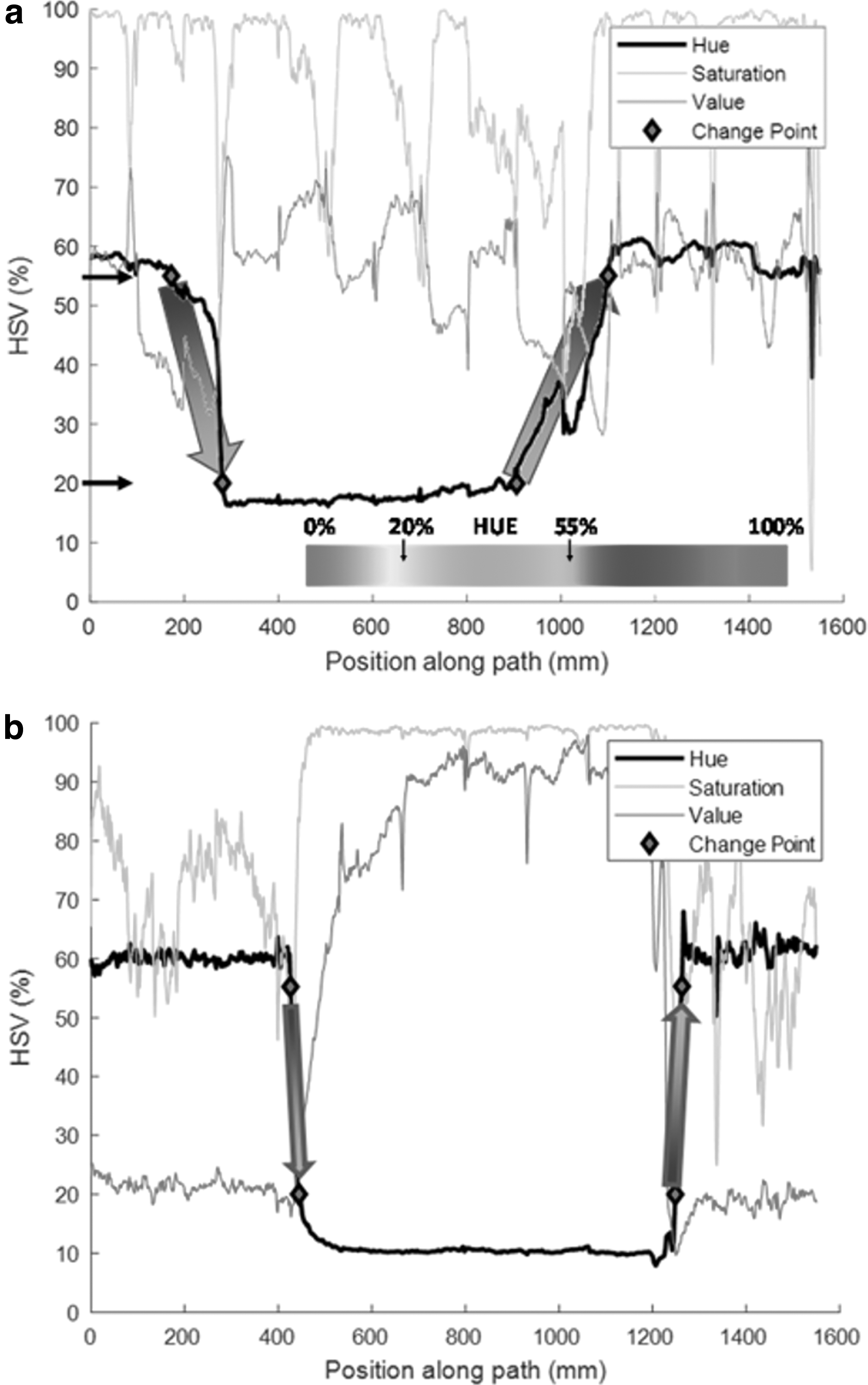
The material transition time was also validated for the third-generation hot end with the multirunner nozzle die (Figs. 1d and 2a). The serpentine print is shown in Figure 6 (bottom), the corresponding hue analysis results are shown in Figure 7 (bottom), and the resulting analysis is presented in Table 3. The transition from blue to yellow occurred in 21.2 mm of deposited road and the transition from yellow to blue occurred in just 3.3 mm. This transition time is greatly reduced when compared with the results presented in Figure 7 (top) for the design of Figure 1c. Using the multirunner nozzle design (Fig. 1d), the transition time has decreased by 87.8 mm (80.6%) when transitioning from blue to yellow, and the transition from yellow to blue has decreased by 191.4 mm (98.3%). This reduction in transition time not only decreases print time and material wastage, but also increases the capability to change material ratios within a single printed part.
Transitional Lengths Required to Change from One Color to Another, Where Blue PLA Is Loaded into the Shell Inlet and Yellow PLA Is Loaded into the Core Inlet
Using the third-generation hot end, an 80.6% decrease in transient distance was observed when transition from blue to yellow and 98.3% when transitioning from yellow to blue.
PLA, polylactic acid.
Test prints
The application capabilities of the hot end were demonstrated by printing a living hinge, a tensile bar with graduated material segments using the second-generation design (Fig. 1c), and toughened impact specimens with stability with respect to thermal annealing. The living hinge (Fig. 8 top) was printed from black PLA for the rigid ends, a 50% PLA/50% TPU coextrudate for the chamfered portions, and neat TPU for the thin center. PLA and TPU are not compatible materials, and thus will not adhere to each other when printed in contact with each other; however, the coextrusion and blending of the two materials provided adequate mechanical interlocking between the deposited roads to create a fully functional hinge for soft robotic applications.18,19

Printed test applications:
A graduated tensile bar (Fig. 8 bottom) was printed with different material ratios along the length of the bar using two different colors of PLA to investigate the ability to custom tailored properties throughout a single print by transitioning from 100% white PLA and transition to 100% black PLA by increments of 25%. The translation between the black and white regions of the print is observable and indicative of the relatively long dynamic transition associated with the second-generation printhead design.
An application area of interest for a system like FD3M is in the printing of high-impact ABS-PC annealed components.5,6 Using the third-generation design, test specimens (62.10 × 12.7 × 3.0 mm) were printed with 100% ABS and 50% ABS shell and 50% PC core. The specimens were then annealed to investigate the dimensional change. The hypothesis is that the PC core with its higher glass-transition temperature (Tg) will provide support to the ABS shell during annealing, reducing any dimensional change.3,5,20 The specimens were printed parallel to the axial direction (horizontal) and perpendicular to the axial direction (vertical).21,22 For each orientation, three 100% ABS specimens and three 50% ABS/50% PC were printed for a total of nine specimens. The specimen dimensions were measured before and after annealing at 110°C for 48 h.
The horizontally printed specimens exhibited dimensional changes as presented in Table 4. The annealed 100% ABS specimen is substantially longer when compared with the annealed 50% ABS/50% PC specimen. The horizontal 100% ABS shrank on average by 8.64% in the x-direction and by 1.24% in the y-direction, while expanding by 11.14% in the z-direction, representing an order of magnitude decrease in dimensional change. The dimensional stability results for the vertically printed specimens are provided in Table 4. Whereas, the horizontal specimens visually shrank in height, the vertical specimens visually became taller in the z-direction after annealing. The vertically annealed 100% ABS specimens on average shrunk in the x-direction by 5.5% and expanded in the y and z-directions by 0.91% and 4.42%, respectively. The resulting standard deviation for the only ABS specimens was 7.08% and 0.24% for the ABS/PC specimens. The reduced dimensional change presented in the postannealed ABS/PC specimens confirms the hypothesis that the addition of PC's increased glass-transition temperature provided a structural support to the ABS shell during annealing.
Dimensional Change of Annealed Specimens
The addition of the polycarbonate core reduced the standard deviation from 7.08% to 0.24%.
PC, polycarbonate; SD, standard deviation.
Discussion
Objectives and tradeoffs with constraints
Using the knowledge gained from the design iterations and validation work of the FD3M system, principal objectives and constraints have been established. The primary objectives were: (1) low residence times (performance measured by the statistical characterization of time from inlet to outlet for each material), and (2) minimized material transition times (performance measured by the time to transition between different segments of deposited material). Both of these objectives are improved by reducing the internal flow channel volumes as driven by flow channel lengths and diameters/thicknesses/widths. However, the minimization of the flow channel dimensions will tend to result in increased melt pressure and decreased melting capacity. As such, the system optimization is limited by current constraints for typical FFF extruders, including a maximum melt pressure of 10 MPa and minimum melting capacity of 5 mm3/s.
Current mechanical design
The implementation of the original spiral flow manifold (Fig. 1c) indicated that the material transition time shown in Figure 7 was not sufficiently rapid enough for use in FD3M printing processes without a purge step. The shorter the material transition time, the more capable the hot end will be at providing different materials within a single printed component. The previous design iterations were designed based off the assumption that the transition time would be solely dependent on the volume of the flow channels where the two materials are combined. However, validation work suggests that the compressibility and/or pressure drop within could cause backflow of one material into the incorrect flow channel. This realization of backflow meant that the volume of the entire polymer feed system needed to be minimized.
The third generation incorporating the flow manifold on the surface of the nozzle (Fig. 1c) is believed to be the simplest possible design. In theory, the nozzle could be integrated with the fastening plate that retains the nozzle from below. In practice, however, the nozzle's small size allows it to be quickly and easily produced from processes such as casting and precision direct metal laser sintering (DMLS). The modular design allows for rapid exchange of the nozzle and the investigation of different nozzle bore designs. Ongoing research is exploring the spiral geometry (Fig. 2b) as well as static mixers (Fig. 4c) and other “X” and clover sections (Fig. 4b) for a variety of materials.
Conclusion
The research and development of FD3M has involved machine and system design, as well as simulation and validation work across 3 concept generations and 14 different design iterations. Lessons with respect to manufacturability, material flow, and thermal control were learned from these iterations, with the latest die nozzle-based design encapsulating all the insights gained from previous iterations. The die nozzle designs' novel interchangeable hot end flow channel opens up the possibility to investigate different flow channel designs without the need of manufacturing an entirely new print head, hence allowing for decreased downtime during the iterative design process. Validation work with the die nozzle-based design has shown promising results, including 90% reduction in transition time, compared with prior design generations, as well as benefits in printing applications, including the dynamic dispensing of varying materials within a printed road and improved dimensional stability in printing ABS/PC composite structures. 23
Footnotes
Acknowledgment
The authors would like to thank Gustavo Medeiro and Antoine Delarue for their help in operating the experimental printer and expertise of cryofracture.
Authors' Contributions
R.G.L.: methodology, validation, investigation, and writing—original draft. C.J.H.: writing—review and editing, supervision. D.O.K.: conceptualization, methodology, software's, writing—review and editing, and supervision.
Disclaimer
Any opinions, findings, and conclusions or recommendations expressed in this material are those of the author(s) and do not necessarily reflect the views of the National Science Foundation or the sponsors.
Author Disclosure Statement
No competing financial interests exist.
Funding Information
This material is based upon work supported by the National Science Foundation under grant number IIP-1822147 (Phase I IUCRC at University of Massachusetts Lowell: Center for Science of Heterogeneous Additive Printing of 3D Materials [SHAP3D]) and from the SHAP3D I/UCRC Members: U.S. Army DEVCOM Soldier Center; U.S. Army DEVCOM Armaments Center; HP, Inc.; Hutchinson; Integrity Industrial Ink Jet Integration LLC; Raytheon Technologies; Stratasys Ltd; A.D.A.M; Akita Innovations; Greene Tweed; Karagozian & Case; Sandia National Laboratories; Desktop Metal; Boeing Company; Triton Systems, Inc.; Mide; Nanoptics; and U.S. Air Force Research Laboratory.
References
Supplementary Material
Please find the following supplemental material available below.
For Open Access articles published under a Creative Commons License, all supplemental material carries the same license as the article it is associated with.
For non-Open Access articles published, all supplemental material carries a non-exclusive license, and permission requests for re-use of supplemental material or any part of supplemental material shall be sent directly to the copyright owner as specified in the copyright notice associated with the article.