
Abstract
Alternative approaches to laser fusion for the additive manufacturing (AM) of metals are often hampered by the need for long sintering cycles. Typical sintering cycles require heating at temperatures above 80% of the melting point for several hours. The process is time- and energy-consuming, particularly when high-melting materials are involved. Applying pressure can drastically reduce the time and temperature required for densification. Recently, a particular kind of pressure-assisted sintering process known as spark plasma sintering (SPS) or field-assisted sintering (FAST) received considerable attention in academia and industry due to its ability to enhance densification. However, conventional SPS/FAST techniques cannot be directly applied to the densification of objects presenting a complex geometry. This work shows how a modified SPS/FAST setup, operating in a pseudoisostatic mode, can be used for debinding and sinter objects produced by material extrusion. This approach can be applied to metals and metal-based and ceramic-based composites when their geometry does not include closed cavities. Depending on the characteristics of the pressure-transfer medium, some level of anisotropy in the volume reduction associated with the densification can be observed. Still, it can easily be corrected by appropriately compensating sintering deformation during printing. Using this approach, the time required for the debinding and sintering can be reduced considerably. It represents an alternative approach to the AM of a wide range of inorganic materials characterized by a relatively low-cost, high material flexibility, and low environmental impact.
Introduction
Additive manufacturing (AM) is rapidly expanding in the automotive, aerospace, oil, and gas industries as an alternative to classical subtractive and powder technologies to realize complex components.1–3 The range of materials that can be processed using this technique has progressively been increased, including metals, ceramics, and several polymers and composite materials.2,4,5
AM technologies for the realization of metallic or ceramic components can be divided into three main groups, all based on the so-called layer-by-layer manufacturing approach. The first group is represented by single-step processes, such as powder bed fusion (PBF) and direct energy deposition (DED). In this study, a localized source with high-energy density—such as a laser or electron beam—is used to fuse or sinter metallic powders deposited in thin layers, obtaining the finished object directly.3,6,7 A second group is indicated by the terms material extrusion (MEX) previously referred to as “robocasting,” direct ink writing, or 3D gel printing. 7 These techniques involve the use of colloidal inks deposited in layers to form the required shape. After printing, specific heat treatment must be performed to transform the green body into a dense and mechanically strong object.
A final group includes processes that involve three or more steps, such as the MEX, in which a heated printer head is used to melt or soften a polymeric filament or pellets loaded with the powders of the desired material,8–10 or vat photopolymerization (VPP), that utilizes a photocurable resin mixed with the powders of the material of interest. In this case, the printed sample generally requires a chemical debinding to remove part of the polymeric matrix, followed by a sintering process to obtain the final object.11,12
The AM of metallic components is based mainly on the first group of technologies. 13 Despite this popularity, PBF and DED technologies present some relevant drawbacks. The apparatuses are quite expensive and complex. They require handling loose metallic powders, which pose hazards and safety issues, and must work in an inert atmosphere that is expensive to maintain. Most importantly, these machines present little flexibility in processable materials and do not generally allow composite and ceramic materials to be realized.1,3,7 Finally, this technique's rapid and localized heating and cooling cycles may result in metastable phases or undesired microstructural features, and some postprinting thermal treatments are usually required.3,6
The AM of ceramic components presents a lower diffusion and is mainly realized using VPP. Reliable and accurate experimental apparatuses based on this approach are now commercially available. VPP allows high-dimensional accuracy, but it also presents some specific limitations. The experimental devices are generally quite complex, do not allow to operate with a high concentration of ceramic powders (usually resulting in long debinding processes), require long sintering processes, involve the use of hazardous chemicals, and present limited material flexibility, as any change in the starting powders requires a complex optimization of the procedure.
The techniques based on colloid extrusion found minimal industrial diffusion, and its application has been limited mainly to ceramic materials.14,15 However, some examples of application on metals have been reported. 16 MEX usually presents lower accuracy but involves significantly lower investment and operational costs. More importantly, this approach offers broad flexibility in processable materials. It also allows the possibility to realize 7 composite materials and objects composed of different materials or presenting compositional gradients. In addition, including the starting powders in gel-like moiety reduces any hazards and safety issues due to volatile micro- or nanometric powders. Despite these advantages, this technology is primarily used only for research applications. This is due, among other reasons, to the necessity to realize long sintering processes, requiring tens of hours or even days and sometimes failing to produce a fully dense object. To overcome these limitations, more efficient sintering methods should be considered.
Innovative sintering processes have been extensively investigated in the last two decades.17–19 Among them, particular interest has been focused on a group of techniques generally indicated as field-assisted sintering (FAST). In particular, spark plasma sintering, or SPS, has received wide attention in research and industrial applications. The terms SPS or FAST generally refer to a pressure-assisted sintering process where the heating of green material does not involve the use of a furnace but is realized by low-voltage, high-intensity current fluxes flowing directly through the container of the sample and, eventually, the sample itself.20,21 This setup offers the possibility to realize very fast sintering cycles, often reduced to a few minutes.
Further beneficial effects associated with high current fluxes have also been remarked. 22 High densification levels can generally be obtained even when difficult to sinter materials, such as refractory metals, high-temperature ceramics, or nanometric materials. SPS/FAST devices, however, use a uniaxial load, allowing to realize only simple geometries, such as disks or cylinders. The production of objects characterized by complex morphology is generally precluded. Some attempts to overcome this limitation have been recently reported in the literature. These involve premachined powder compacts 23 or soft mold made from graphite foil or 3D-printed polymers24,25 and a pseudoisostatic setup.
Our work aim was to extend these approaches even further, avoiding a predefined mold and using MEX to realize the green body. The underlying idea is to couple low-cost, flexibility, and environmental friendliness offered by water-based colloid 3D printing with the rapid and efficient sintering provided by the SPS/FAST processes. Using a sintering process that lasts less than an hour from start to finish can lead to a colloid-based 3D printing process that can be considered “rapid prototyping.” This work presents applications of this approach in the case of two metals (AISI 316L stainless steel and AISI 16Mo3 steel) and one ceramic material (TiO2). However, we believe that a similar approach can be easily extended to realizing most metal–matrix or ceramic–matrix composites and objects, including different metals or ceramic elements.
Experimental Section
The samples presented in this study have been realized using a two-step process involving the realization of green elements by extrusion of water-based colloids followed by a modified SPS/FAST sintering process conducted in the pseudoisostatic mode.
Ink preparation
The inks included water as a solvent, powder of the desired material—with content around 88 wt.% (or 66 vol.%) for metals and 60 wt.% (or 65 vol.%) for titanium dioxide—and a polymeric additive to control the stability and the rheological properties. The overall content of the polymeric binder was limited between 3 and 9 wt.%. The polymer used in our formulation was polyethylene oxide co-polypropylene oxide-co-polyethylene oxide (Pluronic® F-127; Cat. No. P2443, molecular weight 12,600; Sigma Aldrich) prepared as a water solution at 25 wt.%.
We used two steel powders: austenitic stainless steel (AISI 316L) powders with two different grain sizes and chrome-molybdenum steel (AISI 16Mo3) with a melting range of 1370–1400°C and 1420–1460°C, respectively. One batch of AISI 316L powder was obtained from Renishaw (Cat. No. 316L-0407) and was characterized by grains with a spherical shape and an average dimension of 50 μm. The second batch of AISI 316L powders was obtained from US Research Nanomaterials, Inc., and presented a 10 μm average grain size with a broader distribution in shapes and dimensions. The AISI 16Mo3 steel powder was supplied by MIMETE (Cat. No. M16MO3B11010) and presented an average grain size of 50 μm. The TiO2 rutile powder was obtained from Sigma-Aldrich (Cat. No. 224227) and presented an average grain size of <5 μm.
Figure 1 shows scanning electron microscope (SEM) images of all the powders used in this investigation. Figure 1 also shows two powders used as pressure-transfer medium during the pseudoisostatic sintering process, namely Al2O3 from Sigma-Aldrich (Cat. No. 06300), with an average grain size of 100 μm, and SiC from GoodFellow (Cat. No. SI516010), with an average grain size of 70 μm.
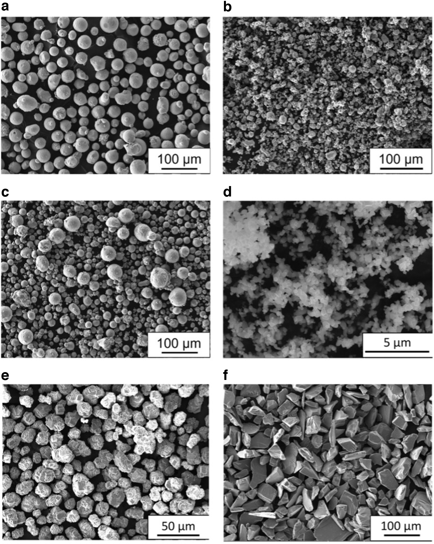
SEM images of the powders used in this study.
Various formulations containing different amounts of metal powder have been realized and characterized to identify the mixture presenting the optimal rheological properties.
Although the formulation includes only three components, the ink preparation could be challenging,15,26 particularly regarding its mixing uniformity. Different types of mixing have been described in the literature: hand mixing, magnetic stirring, or high energy mixing.27,28 All these methods share two main disadvantages. The waste of raw materials represents one. The colloid transfer from the mixer to the extruder is the primary source of waste, as significant amounts of colloids remain adherent to the surfaces of the mixing media and containers. The recovery of this material is possible, but can be difficult and time-consuming. Solvent losses due to evaporation represent the second problem. This problem is critical because ink formulations are generally designed to contain the maximum possible amount of inorganic powders. The rheological properties of such mixtures can change drastically even with a minimum variation in the fraction of solvent, 29 resulting in poor reproducibility in the printing process.
We used a syringe-to-syringe mixing procedure developed in a previous study. 30 In this method, colloid components are placed without mixing directly in the syringe, later used as an extruder (30 mL Nordson EFD). This syringe is then connected to a second empty syringe. Both syringes are cooled below 10°C, at which the Pluronic-water solution shows a low viscosity due to a well-known gel transition.31,32 The mixture is then extruded back and forth between the two syringes at least 50 times using an automatic pneumatic controller. The extensive shear deformation produced by this procedure allows for excellent mixing uniformity. At the end of the process, the two syringes are disconnected, and the ink syringe is mounted directly to the printer head. This approach eliminates any loss in both powder and solvent, allowing optimal printing reproducibility and avoiding any cleaning operation.
Printing apparatus
The green samples have been realized using an in-house modified 3D printer from e3d (ToolChanger & Motion System Bundle), shown in Figure 2. The open frame architecture of this printer allowed to develop dedicated extrusion heads, represented by pneumatically controlled syringes containing the inks. SMC provided the pneumatic components required to control the extrusion. They include three-port pilot-operated poppets (VP342R-5YO1-02FA), precise pressure regulators (IR2020-F02-A), high-precision digital pressure switches (ISE20-P-01-L), and high noise reduction silencers (ANB1-02/03). Upstream, we placed a pressure relief three-port valve (VHS40-F04A) and a filter regulator with a backflow function (AW40-F04*-B) to stabilize the airflow inlet.
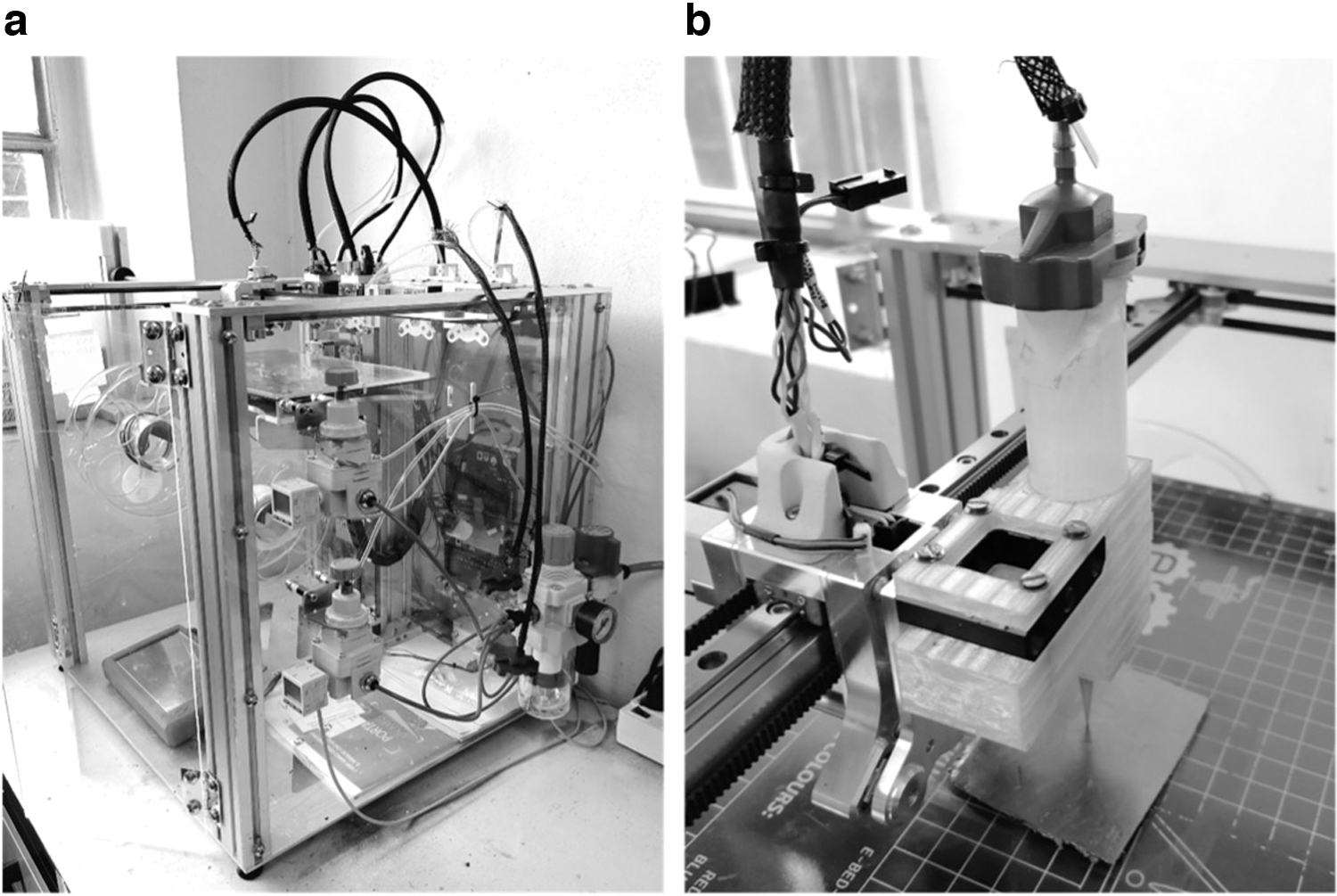
The colloid was extruded through conical needles, presenting an aperture between 0.4 and 0.2 mm (Nordson Optimum® SmoothFlow™ 7018298 and 7005009). Once the ink formulation was defined, the printing parameters were tuned to optimize the quality of the resulting green objects. Printing speed, extrusion pressure, and the size of the extrusion aperture have been optimized for each ink. The open-source software Ultimaker Cura Slicer has been used to regulate printing parameters and generate g.codes derived from computer aided design models. Table 1 shows the settings we used in this work with an applied gas pressure of around 1.5 bar. At the end of the printing process, the objects were dried in the air overnight to eliminate most of the water present in ink. Samples were printed on thin graphite paper that was removed once the samples were dry and ready for the sintering procedure.
Printing Parameters
FAST/SPS
The setup used for the densification of the green bodies is a modification of the conventional setup used in the FAST/SPS method. 33 An image and a schematic of the apparatus we used are shown in Figure 3a. A hydraulic system produces a uniaxial pressure during the densification. The two hydraulic pistons also act as electrodes to supply the current to the sample holder. The current flux is generated by a high-power transformer that produces a maximum AC current of 5000 A at 6 V. The sample is contained in a graphite mold. The current flows through the graphite mold producing rapid heating (up to 1000°C/min). The temperature is controlled by a K-type thermocouple inserted in the lateral wall of the graphite mold. During the sintering process the sample and the mold are maintained under a low vacuum (10 Pa).

To maintain the geometry of the green sample, the densification is performed using a pseudoisostatic configuration. Details of the setup are shown in Figure 3b and c. The green body deriving from the 3D printing process is first placed in the graphite mold over a bed of powders of an inert material, typically represented by coarse-grained alumina, when the sample is metallic, or SiC for oxides (Fig. 3b). Subsequently, the entire green element is covered with the inert powder. Afterward, the top plunger of the graphite mold is positioned (Fig. 3c). An image of a metallic green body placed over the bed of alumina powder inside the graphite mold is shown in Figure 3d. The entire graphite mold is then positioned in the FAST/SPS apparatus shown in Figure 3e. The uniaxial pressure of 70 MPa is applied.
The lateral surface of the die is wrapped with a graphite cloth to reduce the thermal radiation, and the densification process is finally started, allowing a high-intensity current to flow through the die. The temperature was raised with a linear ramp (100°C/min that corresponds to a current flux up to 8.92 GA · m−2) to the final sintering temperature (up to 1250°C). The temperature and the pressure were both maintained for 5 min. The temperature was then reduced with a cooling rate of 50°C/min. Below 600°C the sample was let to cool down naturally. A typical example of temperature and pressure evolution during the sintering procedure used in the case of the sintering of TiO2 powder is presented in Figure 3f. It must be noted as the entire sintering cycle, including heating and cooling, takes less than an hour.
No sintering is produced in the inert powders surrounding the green body at the temperatures used for its densification. As a result, such powder behaves as quite an efficient pressure transfer medium, allowing it to realize a quasi-isostatic pressure distribution acting on all surfaces of the samples and allowing it to maintain its original shape.
Rheological characterization
Rheological analyses were performed using a rotational rheometer (MCR 102, Anton Paar, I) with a parallel plate setup (PP50, diameter = 50 mm) as a measuring system. The measurement gap was set at 1.5 mm. The viscosity of the colloids was measured at increasing shear rates in the range 10–300 s−1 at 10°C and 25°C. Three replicas were performed for each sample.
Dynamic viscoelastic measurements were also carried out. A stress sweep test was performed at 25°C: increasing shear stress values were applied at a constant frequency (1 Hz), while elastic and viscous properties, expressed by the storage (G′) and loss (G″) moduli,34,35 respectively, were assessed. For each sample, the crossover points between G′ and G″ profiles were identified.
Microstructural characterization
Microstructures have been analyzed by optical (Zeiss Axioplan) and SEM microscopy (TESCAN MIRA). Chemical analysis was carried out using energy dispersive X-ray spectroscopy (EDS) analysis using an EDAX apparatus. The same analyses have been performed on metallographic sections included in epoxy resin. Grinding and polishing have been performed using a Buehler system. The final polishing has been performed using a Buehler MicroCloth with a 1 μm colloidal diamond spray.
The densities of the sintered samples have been determined by image analysis of the metallographic sections using the program ImageJ (National Institutes of Health), and by the Archimedes method using EtOH as the liquid medium.
Results and Discussion
Ink rheological characterization
A preliminary study on the influence of metal powder content on the rheological properties of the inks has been performed using the AISI 316L powder with a 50 μm grain size. Figure 4a and b shows the rheological properties of three different mixtures: a solution of water with 25 wt.% of Pluronic, which we used as a reference, the same solution with 83 and 88 wt.% of AISI 316L powder. All the curves present a strongly non-Newtonian behavior, characterized by an evident shear thinning behavior at higher shear rates (Fig. 4a). This behavior is ideal for printing applications, as it offers a low viscosity during the extrusion process and a low deformation of the deposited material.
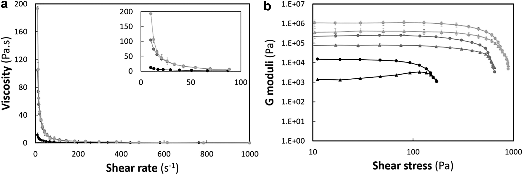
Adding the metallic powder produces a substantial increment in the viscosity and value of the G moduli (Fig. 4b). The viscosity value at 10 s−1 of shear rate increases from 11 ± 3 Pa·s for the Pluronic gel alone, to 104 ± 2 Pa·s for the 83 wt.%, and to 193 ± 3 Pa·s for the 88 wt.% powder content. It can also be noticed that the behavior of the two inks is identical for values of the shear rate above 21 s−1. The powder content increases the viscosity only at very low shear rates, which is desirable in terms of the morphological stability of the extruded ink.
The stress sweep measures confirm this behavior, evidencing as for all the formulations, the elastic modulus G′ is higher than the loss modulus G″ at low values of shear stress, confirming the ability of these mixtures to maintain the shape once extruded. The yield stress, generally identified by the crossover between the G′ and the G″ curves, increases considerably with the powder content. A significant difference is also observed between the two powder loads. We must finally add that inks with AISI 316L powder content above 93 wt.% have been impossible to characterize due to the excessive viscosity of the mixture.
3D printing and sintering procedure
The objects produced during this investigation can be divided into two groups. The first type, shown in Figure 5, is represented by small cubes with a dimension of ∼8 × 8 × 8 mm. These simple elements have been used to evaluate the influence of the experimental sintering conditions on the sample microstructure and geometry. In particular, they have been used to assess the deformation produced by the pseudoisostatic pressure-assisted sintering realized by the SPS/FAST process. The second group, shown in Figure 6, includes objects in different materials presenting various complex geometries realized to demonstrate the potential of the proposed approach. The sintering conditions for each material—summarized in Table 2—have been optimized to obtain maximum density. Due to the low content in the polymeric binder and its low-molecular weight, a dedicated debinding process was not necessary.
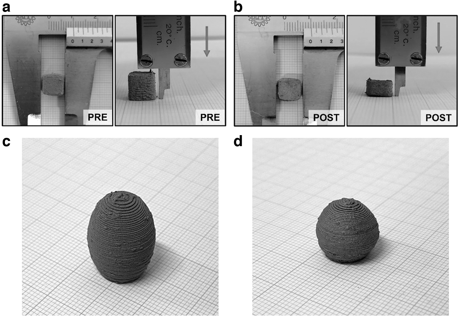
Images of the same sample realized using 50 μm SS316L before
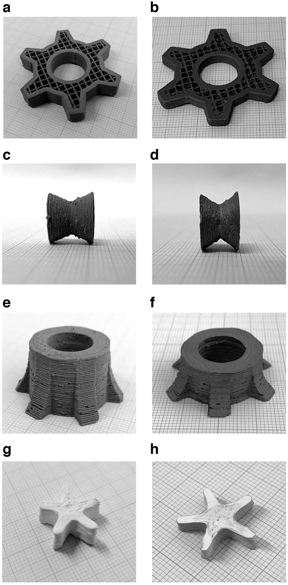
Examples of complex geometries obtained using the approach described in this work. The images on the left column show the green objects obtained by material extrusion, while the images on the right column show the same objects after the SPS/FAST densification.
Sintering Conditions
To confirm that binder residues were not retained in the final material, we performed thermogravimetric analysis analysis in air on samples obtained using inks including or excluding the binder. The samples were ground to a fine powder before the analysis. Samples obtained from inks including the binder have shown only a minimal increase in weight loss (<0.2%), confirming that only a minimal amount of organic residues are retained in the samples at the end of the process. The possibility to avoid a debinding process represents a significant advantage over similar processes proposed previously. 36
It must first be noted that the pseudoisostatic approach used in this study allows for preserving the geometry of the green body with some limitations. Neither alumina nor the silicon carbide powders we used as a pressure-transfer medium behave as an ideal fluid. Although coarse-grained, these powders undergo some degree of compaction during the process. Although they do not show signs of sintering, their compaction reduces the ability to transfer the pressure load uniformly, particularly in the direction perpendicular to the applied load. The result is evidenced in Figure 5, where a small cube is shown before and after the SPS/FAST process. The red arrow indicates the direction of the external pressure applied during the sintering process.
The relative density of the sample increased from 50% in the green body to 96% in the final sample. However, the corresponding volume reduction is distributed unevenly. It is evident as most of the volume contraction (about 60%) was in the direction parallel to the direction of the externally applied load. No significant variation in the other two dimensions has been observed. As a result, the geometry is preserved, although somehow deformed.
This deformation can be reduced using other and more efficient pressure-transfer mediums. However, since the observed deformation is quite reproducible, its effect can be corrected by appropriately rescaling the green body geometry. This possibility is shown in Figure 5c in which a rescaled object is printed considering this deformation to obtain the desired spherical shape (Fig. 5d). In any case, the deformation does not preclude the possibility of realizing complex objects. Some examples are reported in Figure 6, where some geometries, realized with different materials, are shown as green bodies and after the SPS/FAST sintering. The volume contraction in the direction of the applied load is evident in all cases, but it must be noted how the geometry details are otherwise remarkably preserved.
The only limitation in the type of geometries obtained through this approach is related to the possibility of the geometry sustaining itself during the printing process. Due to the viscous behavior of the extruded colloid, structures presenting significant overhanging features tend to deform under the weight of the subsequent layers. Of course, the extent of the deformation depends on the nature of the colloid under use and the overall geometry. Still, as a rule of thumb, it must be considered that overhanging features can be sustained if they present an inclination above 30° from the building plate. Smaller inclinations spanning between 30° and 0° require supporting materials. We have been working on the possibility of using supporting materials deposited using a second extruder. A detailed description of this approach will be presented in a following publication.
However, the presented examples evidence the flexibility of the proposed approach, which can be applied to different materials with similar results using minimal modifications to the experimental procedure.
Microstructural characterization
An example of the influence that sintering temperature and pressure exerted on the relative density of the material is reported in Figure 7 in the case of the AISI 316L powders. In Figure 7a is shown the trend of relative density as a function of the sintering temperature for an applied pressure of 55 MPa using powders with a grain size of both 10 and 50 μm. The two powders show very similar behavior, reaching relative densities above 90% for temperatures approaching 1200°C. The only significant difference can be observed at low temperatures (700°C), where the smaller grain size produces a higher relative density. It is worth noting again that these relative density levels have been obtained using a sintering time of only 5 min.
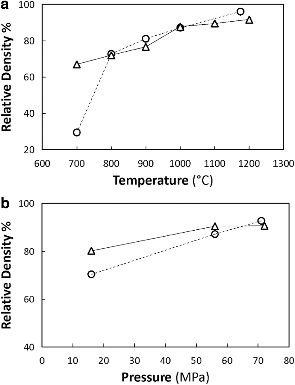
The influence of the applied uniaxial pressure on samples produced using the same powders is shown in Figure 7b. All samples have been sintered at a temperature of 1000°C. A significant increase in relative density is obtained by increasing the uniaxial pressure from 15 to 55 MPa. However, a further increase in the pressure seems to produce only marginal effects.
The smaller grain size is more efficient in producing denser materials when milder sintering conditions are used. However, the differences between the two particle sizes are minimal at higher temperatures and pressures. The powder presenting the larger grain size seems to produce samples with slightly higher relative densities in these conditions.
The microstructures of some of these samples are shown in Figure 8. In this study, back scattered-scanning electron microscope images of metallographic sections of samples obtained using both 10 and 50 μm grain sizes are reported for two different sintering temperatures (800°C and 1200°C) and a pressure of 55 MPa. These images confirm the trend evidenced in Figure 7a. It is evident as the smaller grain size produces a denser material at the lower temperature. In contrast, at higher temperatures, both samples are considerably denser. Some residual microporosity can be observed at the grain boundaries in agreement with the literature relative to stainless steel sintering in SPS. 37 No evidence of anisotropy can be observed in the microstructure, suggesting that the pressure distribution during the sintering process was quite uniform.
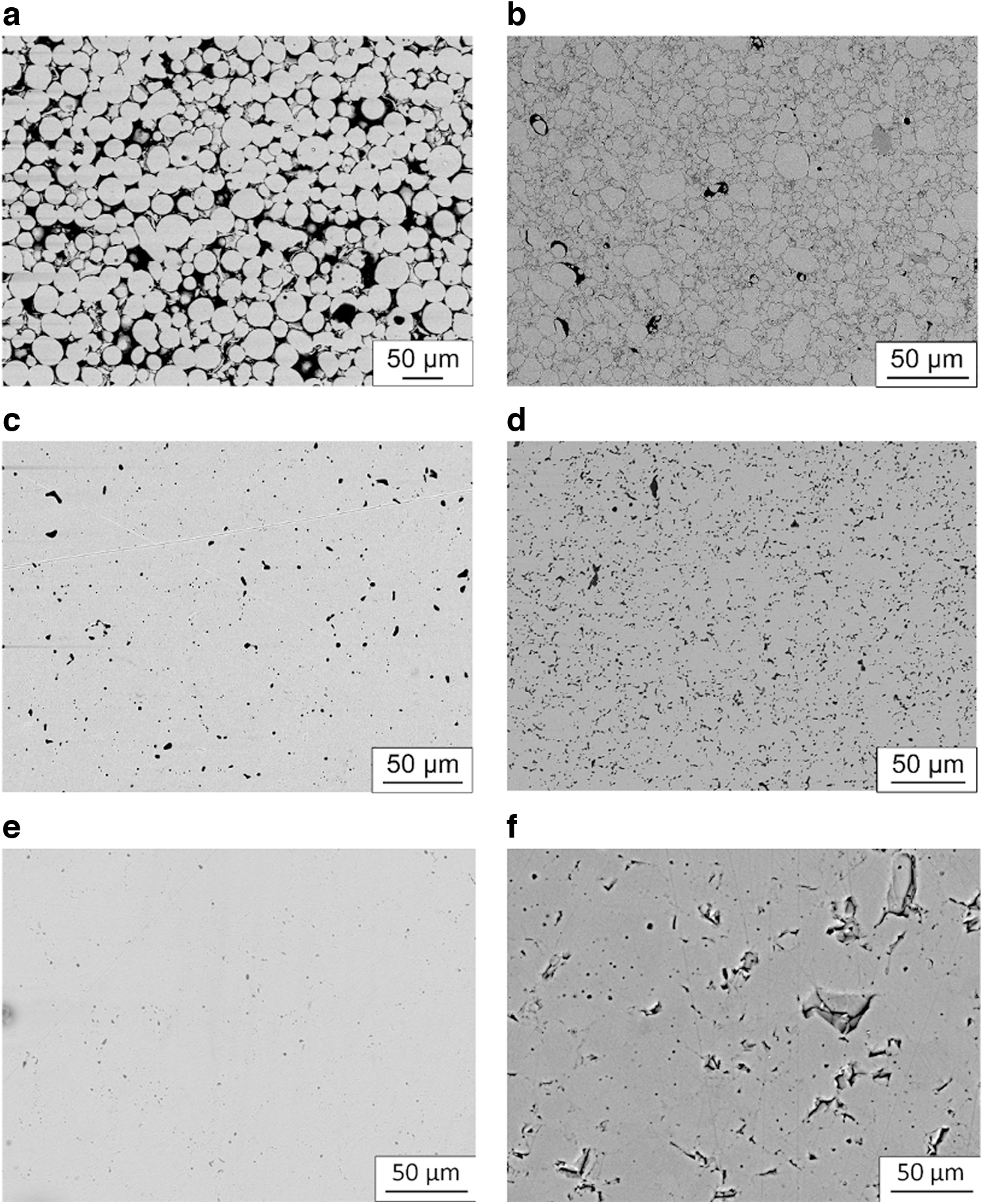
The microstructure for AISI 16Mo3 and TiO2 samples produced with the same approach can be seen in Figure 8. The sintering conditions and the resulting relative densities for these materials are summarized in Table 2. Figure 8e and f shows that these materials allow obtaining high levels of relative densities, with microstructures characterized by a minimal content of residual porosity.
Conclusion
In this work, we presented a new combination of material extrusion and pressure-assisted sintering, drastically reducing the time required to realize fully sintered components produced by the extrusion of water-based colloids. This was achieved by modifying the conventional setup in SPS/FAST sintering systems, allowing to retain the geometry of a green body produced by material extrusion. In most cases, this approach reduces the sintering time to just a few minutes. It also allows taking full advantage of MEX low-cost, high flexibility, and low environmental impact. The approach successfully produced objects realized with metals and ceramic materials. Still, it can be easily adapted to making metal- or ceramic-based and functionally graded composite materials. The short processing time and the broad flexibility suggest that this approach is particularly well suited for applications of fast prototyping when producing small volumes of objects with various characteristics and compositions required.
Footnotes
Acknowledgment
The authors would like to thank the CISRiC for using the SEM facility.
Authors' Contributions
R.B. and L.A.: methodology and investigation; and experimental measurements. P.B.: support to methodology and technology development. B.V. and S.R.: experimental measurements. F.A.: supervision and writing—reviewing and editing. U.A.-T.: conceptualization, supervision, and writing—original draft preparation. S.M.: supervision and writing—reviewing and editing.
Author Disclosure Statement
No competing or personal financial interests exist.
Funding Information
This work was partially supported by the Italian Minister of University and Research through the project “A BRIDGE TO THE FUTURE: Computational methods, innovative applications, experimental validations of new materials and technologies” (No. 2017L7X3CS) within the PRIN 2017 program. Regione Lombardia also partially supported this work through the project “MADE4LO—Metal ADditivE for LOmbardy” (No. 240963) within the POR FESR 2014–2020 program.