




Abstract
In this study, NiTi shape memory alloy was prepared by double-wire + arc additive manufacturing plus in situ heat treatment using TA1 and ER-Ni welding wires as the raw materials. The results show that the microstructural evolution from the bottom to top is NiTi2 + NiTi → NiTi + Ni3Ti + Ni4Ti3 → NiTi + Ni4Ti3 + Ni3Ti2 + Ni3Ti + α-Ti. Complex thermal cycles led to the precipitation of Ni3Ti, which improves the hardness of the matrix (B2), and the average hardness value of the top region reaches 550.7 HV0.2. The fracture stress is 2075 ± 138.4 MPa and the fracture strain is 11.2 ± 1.27%. The sample shows 7.02% residual strain and 5.87% reversible strain after 15 cycles, and the stress hysteresis decreases with an increase in cyclic strain.
Introduction
In recent years, the double-wire + arc additive manufacturing (D-WAAM) process has been widely used in various fields due to its high flexibility, high deposition rate, low cost, and high efficiency.1–4 D-WAAM can use two wires with different components to meet the preset components in production. This technology has been applied to prepare various advanced materials. Such as functionally graded materials, NiTi shape memory alloys and TiAl alloys.5–8
The unique superelasticity (SE) and shape memory effect of NiTi-based shape memory alloy has been widely used in medical, aerospace, and automotive fields.9–12 The traditional manufacturing methods of NiTi alloy include powder metallurgy and casting. However, these methods have a great limitation in the complexity of preparing parts. At the same time, the powder has a large surface area, which is easy to attach impurities such as oxygen and carbon in the air, and there is a great limitation in the preparation of complex or large parts. The wide application of wire + arc additive manufacturing (WAAM) provides a novel idea for preparing NiTi memory alloys. 13 Zuo et al. 14 prepared NiTiTa ternary alloy by WAAM process using NiTi alloy wire and Ta foil as raw materials.
The microstructure, phase transformation behavior, and mechanical properties of the alloy were systematically studied. However, the preparation of NiTi welding wire is difficult to draw, and the cost for NiTi components manufactured by traditional single-wire WAAM is high. Therefore, D-WAAM with pure Ti and Ni wire as raw materials was recommended. And various studies want to adjust the technology to adapt to potential applications so that the performance of the deposited components can be close to the samples produced by traditional technology.15–18 However, the NiTi shape memory alloy prepared by WAAM generates NiTi2 precipitates, which greatly affects the performance of the material.
In this case, heat treatment is an effective solution to eliminate NiTi2 precipitates, especially solid solution treatment and aging treatment. 19 In the existing research, solution and aging treatment helped to reduce the content of NiTi2 in NiTi matrix. Jiang et al. 20 treated Ni50.9Ti49.1 shape memory alloy at 1123K for 2 h and then aged at 573K, 723K, and 873K for 2 h, respectively. Finally, a decrease in NiTi2 content was observed. Kaya et al. 21 obtained porous single-phase B2 shape memory alloy with high chemical uniformity by applying load during solution treatment at 1050°C. These two schemes are of great significance to improve the functional properties and mechanical properties of NiTi shape memory alloy. However, the subsequent heat treatment consumes more time and prolongs the production cycle of the parts.
The deposition process of WAAM is often accompanied by a complex thermal cycle, which can be approximated as a heat treatment process. 6 Therefore, in this study, NiTi shape memory alloy was prepared by D-WAAM system using TA1 and ER-Ni welding wires as raw materials and in situ heat treatment process with the interlayer insulation and slow cooling after deposition. The microstructure and properties of as-built were studied.
Materials and Methods
In this study, the experimental system included a gas tungsten arc welding (GTAW) power, a GTAW torch, a trailing gas shield, and two wire feeders. The deposition current is 120 A and the deposition voltage is 10 V. The welding wires used are TA1 (1500 mm/min) and ER-Ni (1045 mm/min) wires with a diameter of 1.2 mm. The substrate is Ti6Al4V. The protective gas flow of both GTAW torch and gas shield is 15 L/min. The substrate preheating temperature is 600°C, the interlayer holding time is 2 min, and slow cooling is performed after the deposition. The metallographic samples were corroded for ∼50 s. A total of 15 layers were deposited on the substrate, and the length of the single-wall component was 175 mm, the height was 25 mm, and the width was 10 mm.
After the deposition of each layer is completed, the temperature of the heating plate is maintained at 600°C for 2 min and covered with insulation cotton. After the deposition of the whole component is completed, the insulation cotton is covered on the component, and the cooling rate of the heating plate is 5°C/min.
The microstructure and fracture were observed by optical microscope and scanning electron microscope (SEM) equipped with an energy dispersive spectrometer (EDS) system. The phase composition of the construction direction was studied by X-ray diffraction (XRD). Finally, the microhardness test, uniaxial compression test, and cyclic compression test were carried out to explore its mechanical properties. The sampling diagram is shown in Figure 1.

Single-wall component sampling location diagram. XRD, X-ray diffraction.
Results and Discussion
The components were divided into three parts, and XRD tests were carried out, respectively. As shown in Figure 2-a1, the phase at the bottom location was composed of B2, B19′ phase and NiTi2 phase. The phase composition at the middle location (Fig. 2-b1) was composed of the B2 phase, Ni3Ti phase, Ni4Ti3 phase, and Ni3Ti2 phase, and the phase composition at the top region (Fig. 2-c1) was the B2 phase, Ni3Ti phase, Ni4Ti3 phase, and Ni3Ti2 phase. Among them, with an increase in deposition height, NiTi2 and Ni4Ti3 decrease gradually, whereas Ni3Ti and Ni3Ti2 increase gradually. Among them, NiTi2 is the main precipitated phase at the bottom, and Ni3Ti is the main precipitated phase at the middle and top.
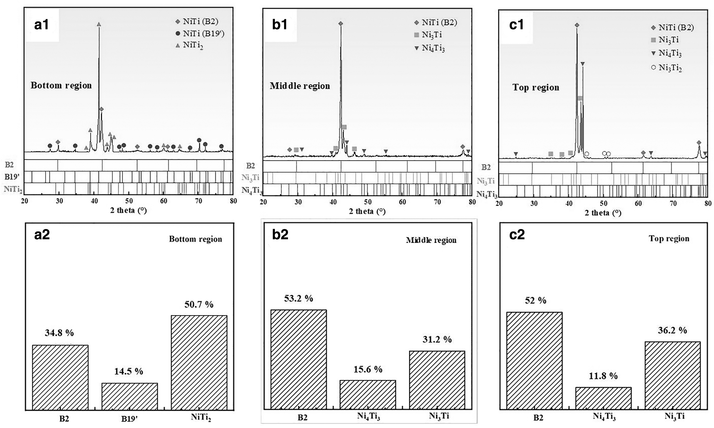
The result of XRD in three locations of the wire + arc additive manufacturing component:
Figure 3 shows the SEM images from the top to bottom. Combined with EDS analysis in Table 1, there were Ni3Ti, Ni3Ti2, and NiTi at the top location. In addition to the intermetallic compounds found in XRD, there is also α-Ti (Fig. 3b, c). There may be two reasons for the appearance of α-Ti: (1) Ti exists here as secondary α-Ti, and the precipitation of secondary α-Ti occurs when Ti alloy is aged at 400–550°C, which further indicates that this method has an effect of heat treatment. (2) According to the phase diagram of Ni–Ti binary alloy, the eutectoid reaction occurs during the solidification of NiTi alloy: β → α + Ti2Ni. 22 In this study, the slow cooling after deposition can be regarded as an annealing treatment, which leads to the generation of α-Ti.
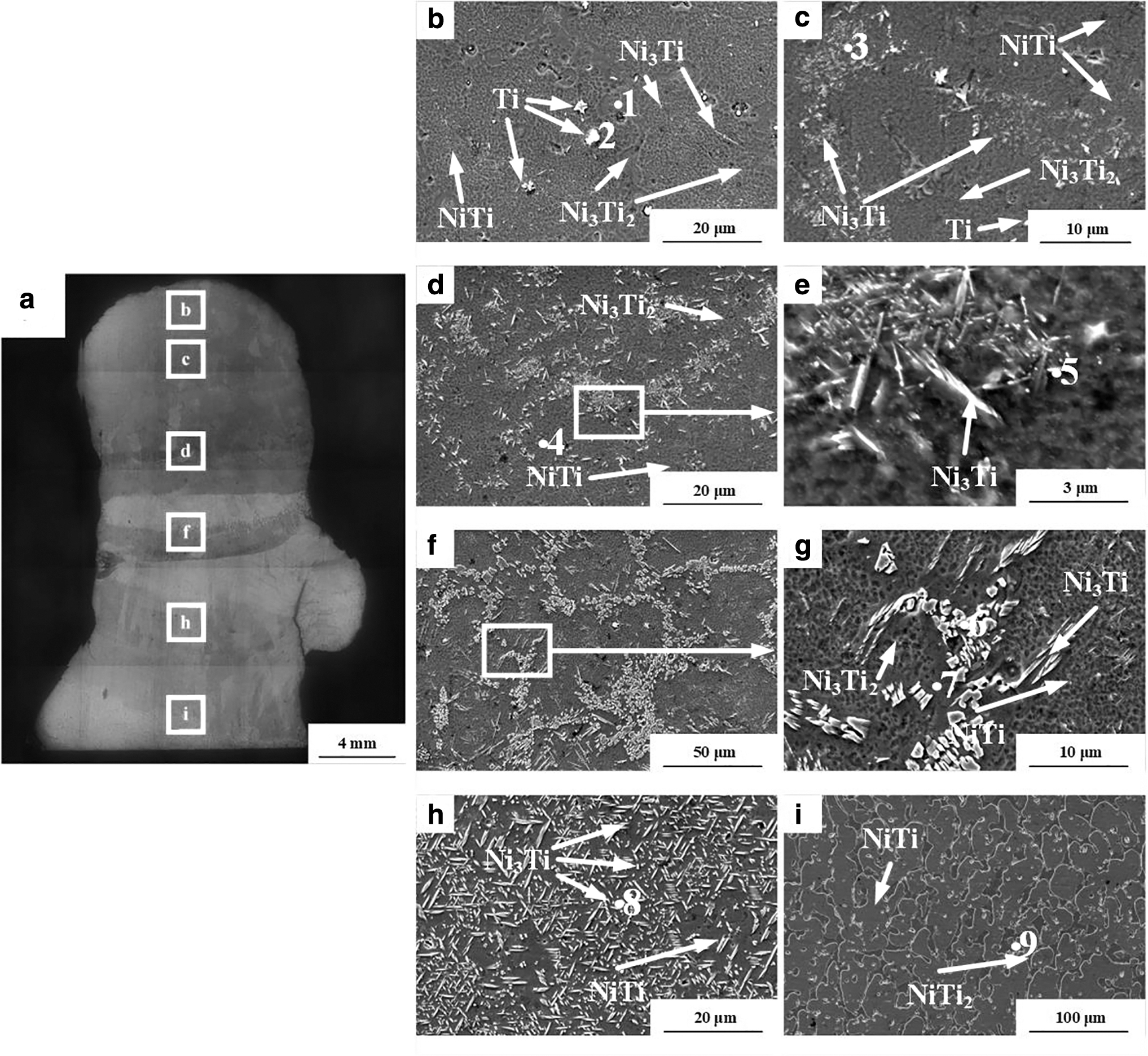
Microstructure of the components:
Energy Dispersive Spectrometer Results of Selected Points in SEM (at.%)
The formation location and morphology of Ni3Ti are also interesting. In the region near the top (Fig. 3b), Ni3Ti precipitates as fine acicular aggregates, and in the central region of the single-wall component, Ni3Ti precipitates between the grains of NiTi matrix (Fig. 3f). The part near the dilution zone exists in the matrix as needle (Fig. 3h), and the phase composition of this part is consistent with that of XRD. According to the classical theory of solid–solid phase transition, nanoprecipitates tend to concentrate in the grain boundary region in coarse-grained NiTi alloy, resulting in the uneven distribution of Ni4Ti3 particles between the grain boundary and the grain interior (Fig. 3d, f). The decrease in grain size can promote the uniform distribution of Ni4Ti3 particles in the grain boundary region and within the grain (Fig. 3h).
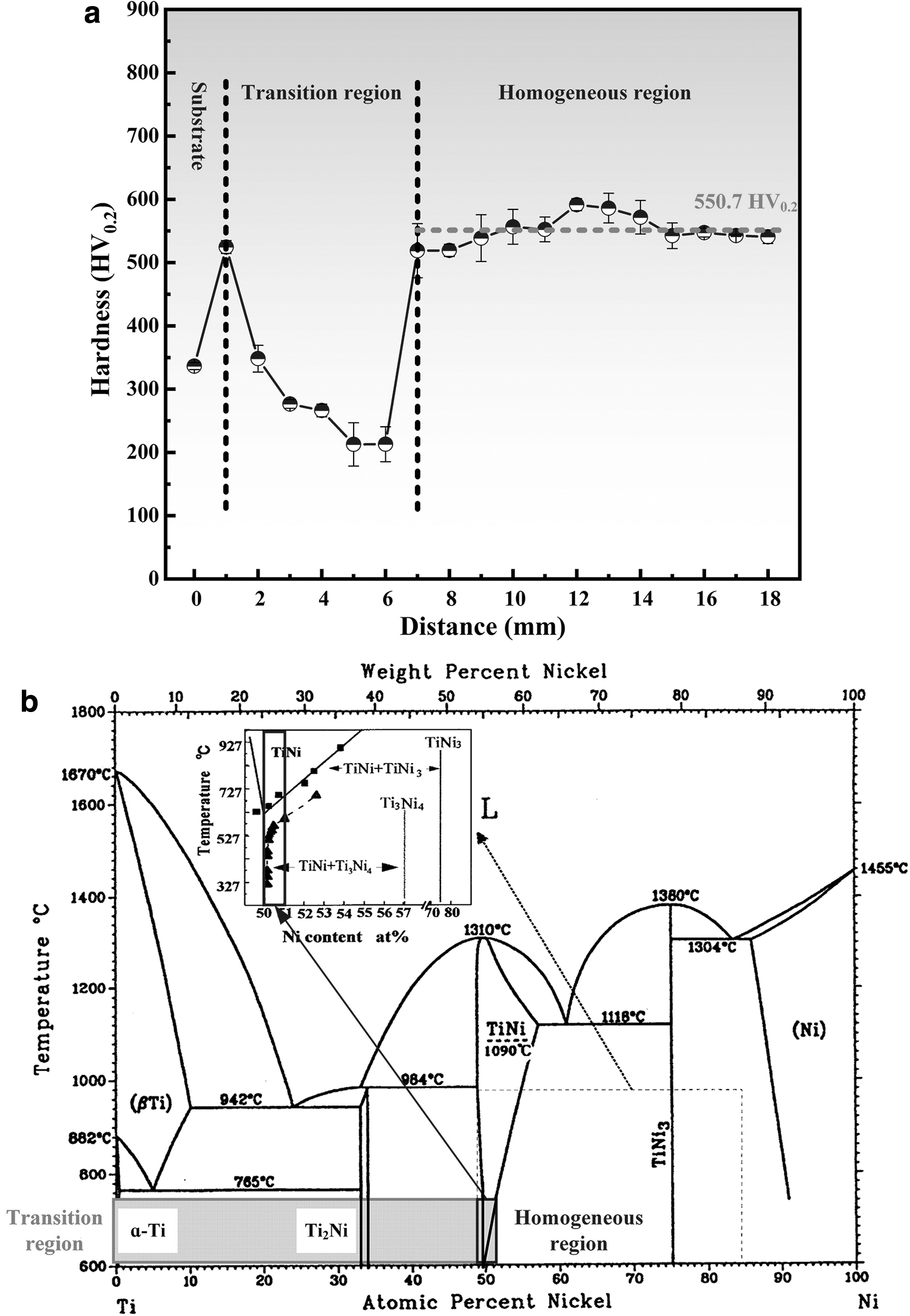
Figure 4a shows the hardness curve of the component from the bottom to the top. Correlating the hardness curve with the Ni–Ti binary alloy phase diagram and the microstructure under SEM, first, the substrate was TC4, and the hardness value was ∼340.3 HV0.2. Then, with the increase of Ni content, the microstructure was transformed into NiTi2 + α-Ti (Fig. 4b), and the hardness rose to 550.7 HV0.2. With the continuous increased of Ni content in the deposition direction, the precipitation of NiTi2 phase gradually decreased, and the curve showed a decrease in hardness until it reached about 203.4 HV0.2. Subsequently, due to the solid phase transformation caused by in situ heat treatment, Ni4Ti3 transformed into Ni3Ti. As shown in Figure 3h, it is NiTi matrix and Ni3Ti precipitated phase. With the precipitation of Ni3Ti, the hardness of the whole component began to rise and gradually tends to be stable, ∼550.7 HV0.2.
The compression samples were prepared along the building direction. The uniaxial compression and cyclic compression experiments were carried out on the components. The uniaxial compression curve (Fig. 5a) and cyclic compression curve (Fig. 5b) were obtained in Figure 5. The fracture stress is 2075 ± 138.4 MPa and the fracture strain is 11.2 ± 1.27%. It is well known that the most obvious feature of NiTi shape memory alloy in superelastic deformation behavior is the stress platform in the stress–strain curve. 23 The length of the plateau can reflect the quality of the superelastic strain. According to the research of Liu et al., 24 the stress modes of NiTi shape memory alloy under uniaxial tensile test and uniaxial compression test are different.

In the tensile test, it can be observed that two adjacent martensites form a composite twin between each other and reorientate through the migration of the interface. In the compression test, no twin relationship and interface movement were observed, and only high-density dislocations were observed. The generation and migration of dislocations lead to work hardening of the material, resulting in no obvious stress platform. Among the intermetallic compounds of Ni–Ti binary alloy system, Ni3Ti has the highest hardness compared with other intermetallic compounds. 25 When the brittle hard phase Ni3Ti appears in the matrix, it has an adverse effect on the fracture strain due to the high internal stress and a large number of dislocations. 16
At the same time, Ni3Ti also forms a slip barrier at the matrix-precipitation interface. 26 Silcock's 27 research also shows that if three of the slip directions in each bcc matrix are not parallel to the possible slip directions in a given second phase, the remaining slip directions need to be broken by strong chemical bonds. The SE of the material was tested at 1300 MPa. The sample showed 6.41% residual strain and 5.92% reversible strain in the first cycle, whereas these values are ∼7.02% and 5.87% after 15 cycles. The results are shown in Figure 5c that the reversible strain tends to be stable with the increase in loading and unloading cycles, and the stress hysteresis decreases with an increase in cyclic strain.
This phenomenon belongs to the stability of stress-induced martensite. When the stress-induced martensite is formed, the process of WAAM produces uneven microstructure and the second phase, which makes local stress concentration in the process of the superelastic cycle, resulting in plastic deformation of the parent phase and irreversible strain. The elastic interface of strain martensite is destroyed, so the phase transformation hysteresis tends to a great stable value, and the strain recovery rate is significantly reduced.28,29
Through the observation of fracture, the fracture mainly presents two kinds of morphology, which appear as transgranular fracture as shown in Figure 6a, and intergranular fracture as shown in Figure 6c, respectively. The initiation and propagation of microcracks in the matrix accelerated the failure of the compressed specimen. The columnar crystal characteristics can be observed from the fracture of intergranular fracture. From Figure 6b to d, there are microcracks, tearing ridges, and spalling in the component, which are typical brittle fracture characteristics. When the tearing ridge is enlarged, a small number of microcracks and discontinuous dimples were found. The appearance of dimples indicates that there are local plastic deformation and ductile fracture in the fracture of the component. Therefore, NiTi-based shape memory alloy prepared by in situ heat treatment process is a ductile-brittle mixed fracture.

Conclusion
NiTi shape memory alloy single-track wall components with in situ heat treatment effect were prepared by D-WAAM process with interlayer insulation and slow cooling after deposition.
With an increase of deposition height, the microstructure evolution is NiTi2 + NiTi → NiTi + Ni3Ti + Ni4Ti3 → NiTi + Ni3Ti + Ni4Ti3+ Ni3Ti2 + α-Ti.
The precipitation of Ni3Ti improves the hardness of the matrix, and the hardness value of the uniform zone reaches 550.7 HV0.2.
The fracture strength is 2075 MPa and the fracture strain is 11.2%. The sample shows 7.02% residual strain and 5.87% reversible strain after 15 cycles and the stress hysteresis decreases with an increase of cyclic strain.
Footnotes
Authors' Contributions
Resources, supervision, and methodology by J.H. Data curation, formal analysis, and writing—original draft by X.C. Investigation by G.Z. and B.L. Resources by M.M., Y.C., H.J., M.B., and Y.H. Methodology and conceptualization by Y.T.
Author Disclosure Statement
No competing financial interests exist.
Funding Information
This work was supported by the Tianjin multiple input projects (22JCYBJC01610).