
Abstract
Auxetic honeycomb structures have been applied in lightweight sandwich structure and impact energy absorption applications due to their unique deformation performance. Based on the traditional two-dimensional reentrant honeycomb structure, a modified three-dimensional (3D) reentrant lattice structure with negative Poisson's ratio (NPR) is proposed. The studies on fabrication and design parameters are conducted, leading to a new understanding of the effects of these parameters on the printing quality and mechanical properties of such lattice structure with reentrant diagonal struts. Additive manufacturing (AM), specifically laser powder bed fusion, is used to fabricate five groups of 18Ni350 Maraging Steel samples with different geometric and printing parameters. The compression test is conducted to obtain the effects of NPR on the quasi-static stress-strain relationship of the proposed structure. The results show that smaller hatch distance and scan speed for 3D printing process can lead to less porosity level and more complete printing, resulting in larger stiffness and yield strength of the structure. The preferred AM process variables to improve structural quality with thin angled struts (diameter ≤0.5 mm) are presented. Moreover, with the help of the tuned finite element model based on experimental results, parametric analysis is conducted to confirm the effect of design parameters, including reentrant angle, strut cross-section shape, and size, on the compressive properties of the structure.
Introduction
Different from traditional materials whose properties are determined by their composition, cellular structure materials can exhibit unique mechanical behaviors derived from their microstructural geometry. Due to the excellent behaviors in energy absorption (EA), lightweight design, etc., cellular structures have been applied in a wide range of fields, including military, transportation, aircraft, automotive industries, and so on.1–3
Auxetic structures that exhibit negative Poisson's ratios (NPRs) in one or more directions are a kind of cellular structures attracting a great deal of attention by the scholars.4,5 Unlike most of the regular materials and structures, auxetic structures exhibit an unusual counterintuitive relationship that transversely expands under axial extension or shrinks under axial compression.
Dating back to 1984, Herakovich found auxetic behavior existing in a laminate composite oriented in specific ways. 6 However, it was not until 3 years later that Lakes 7 formally defined the conception of auxetic structures. Lakes created a rather novel but simple structure in his work that could exhibit isotropic NPR in three principal directions.
Soon after Lakes' work was published, other scholars became aware of the potential of auxetic structures and focused on related studies. Different kind of auxetic structures, including rotating unit structures, 8 re-entrant hexagonal structures, 9 star shape structures, 10 double-arrowed auxetic structures, 11 etc., are successively proposed.
The research on auxetic structures includes quasi-static behaviors3,12 dynamic behaviors under from low-speed to high-speed impact,13,14 and even penetration resistance.15,16 These studies explicitly demonstrate the extraordinary property of the auxetic structures.
First, due to the “volumetric shrinkage” behavior during the compression, the auxetic structure shows higher stiffness for localized bending, which indicates that the indentation resistance is higher than regular structures.17,18 Besides, it also has been verified experimentally and theoretically that auxetic structures show higher fracture toughness. 19
As the Poisson's ratio value of the structure gets smaller (more negative), the fracture toughness increases. 20 Moreover, auxetic structures exhibit a higher energy dissipation and absorption capability than other traditional regular structures, under both quasi-static and dynamic cyclic loading. 21 Even under the high-speed impact, the auxetic structures exhibit much higher resilience compared with the regular structures.22,23
Topologically, the auxetic lattice structures are further classified into two-dimensional (2D) and three-dimensional (3D) lattice structures. The 2D periodic lattice structures are relatively easy to fabricate as the structures can be layer-by-layer built in the extruding direction.
On the other hand, 3D periodic lattice structures with unit cells repeating in all three principal directions are topologically more complex. Therefore, for a macroscopical perspective, 3D auxetic structures are difficult to quickly manufacture with traditional manufacturing methods such as electrical discharge machining (EDM). 24
Francesconi et al. 25 fabricated a stainless steel auxetic structure with the dimension of 305 × 50 × 1 mm by using EDM and a computer numerical control (CNC) machine to conduct static and modal analyses. Chen et al. 26 conducted an experimental study of blast response on sandwich panels with auxetic reentrant and regular hexagonal honeycomb cores, where the samples were also fabricated by CNC folding and EDM. However, when it comes to more complicated 3D auxetic structures, CNC with EDM is not a good way to conveniently and economically fabricate auxetic structures.
Nowadays, due to the layer-by-layer manufacturing feature, the laser powder bed fusion (LPBF) additive manufacturing (AM) process can efficiently manufacture structures with complex geometry. Song's team27,28 proposed an open-cell rhombic dodecahedron lattice structure and fabricated corresponding samples made of Ti–6Al–4V using LPBF AM.
Their comprehensive investigation results, obtained from both experiments and simulations, indicated that the structure exhibits remarkable energy-absorbing capacity. Cao et al. 29 modified rhombic dodecahedron lattice structures and then investigated the quasi-static compression behavior of LPBF built samples with stainless steel 316L.
Compared with the original structure with uniform strut cross-section, the proposed design exhibited better mechanical properties and EA. Gümrük and Mines 30 studied the compressive behavior of metallic body centered cubic structures fabricated by LPBF and the experimental mechanical properties agreed well with the numerical results. Lvov et al. proposed a 3D auxetic structure fabricated through LPBF and found that the new structure can withstand greater cyclic compressive loads than the regular non-auxetic counterparts. 31
From the studies about auxetic structures cited earlier, limited studies have been done on the influence of AM process variables and geometry design parameters on the performance of auxetic structures. In the present work, the effects of AM processing variables and geometry parameters on mechanical behaviors of auxetic structures, especially with angled thin struts, which are usually not easy to be fabricated, are studied and reported.
Based on the traditional 2D reentrant honeycomb structure, a novel 3D reentrant lattice structure that exhibits NPR is proposed and studied. The LPBF AM process was used to fabricate five groups of 18Ni350 Maraging Steel samples with different design parameters, which were then used to conduct quasi-static compressive experiments.
Since there are deviations between the AM-built structures and the as-designed ones, a finite element (FE) model with modified material properties is applied to study the relationship between the mechanical properties and the design parameters. The dimensional errors deviated from the as-designed computer-aided design (CAD) model tends to be an inevitable weakening effect on the mechanical properties of the structure, of which the effect is taken into account in our proposed FE model.
In addition, different from previous literature where mechanical properties are reported only for elastic stiffness and strength, in this study, the relationship between printing parameters, geometrical parameters, and mechanical properties is discussed. The results show how the 3D printing variables, including power, scan speed, and hatch distance, affect the printing quality, thus resulting in varied compressive performances of the structures.
Moreover, with the additional help of the FE model, parametric analysis is conducted to investigate the effect of geometry design parameters, including reentrant angle, strut cross-section, on the compressive property of the structure.
The study on this modified 3D reentrant auxetic structure focuses on two aspects, that is, the effects of printing parameters on the manufacturability, printing quality, and mechanical behaviors of reentrant lattice with diagonal strut supports, and the mechanical properties of the proposed structures with different geometry design parameters.
The study is organized as follows. In Section 2, the geometry design of the proposed structure is described and the design parameters are defined. In Section 3, the printing parameters for LPBF process to fabricate the samples and the quasi-static experiment are provided. Further, in Section 4, the experimental results and corresponding parametric analysis are presented.
Design and Methodology
Geometry description
Numerous auxetic structures have been proposed in the literatures, the majority of which are 2D structures with a single direction NPR behavior. Some of these geometries can be easily translated into 3D structure, whereas other structures with significant chirality cannot be readily translated into 3D structures with the same symmetry. Here in this work, a typical 2D re-entrant lattice auxetic structure is adopted and extended into a 3D lattice structure.
The unit cell of the proposed reentrant structure is shown in Figure 1a. As seen from the front view, the unit cell is a typical 2D reentrant unit cell, as shown in Figure 1b. The unit cell is determined by five independent design parameters as listed in Table 1.
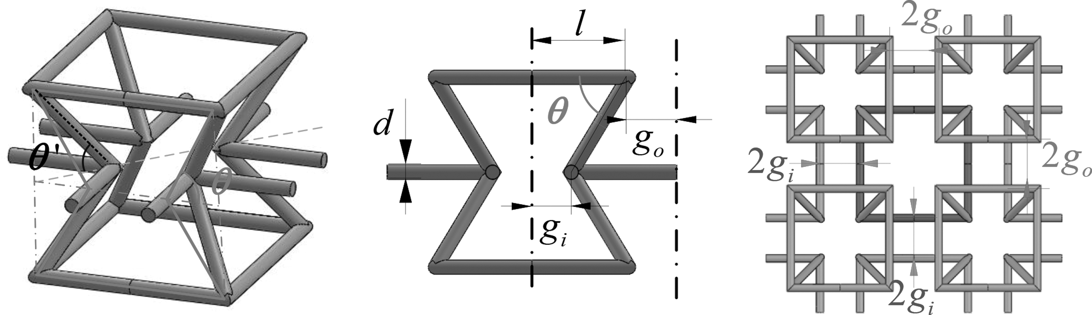
Geometry illustration of the unit cell from different views.
Geometric Parameters for the Structure
The parameter l is the half side length of the top and bottom square, and
All struts of the modified 3D unit cell have a uniform cross-section. It should be noted that the cross-section of the struts could be different shapes, whereas in this paper, circle and square cross-section are investigated and compared. Finally, d is defined as the diameter for circle cross-section, or defined as the side length for square cross-section.
The design idea is when we assemble the unit cells into an array structure, and the new unit cell is “created” among the unit cells. The mutual actions between the original unit cells and the “new” created unit cells generate a shrinking trend when subjected to outer compressive loading, hence it results in NPR behavior.
Figure 2 illustrates that all eight-unit cells adjacent to one another build a new unit cell in the center of the eight-unit cells. Based on this coupling/overlap construction, the proposed lattice structure can generate coupling force to perform NPR.

Illustration of coupling unit.
Crashworthiness indices
In this section, the measurement of NPR and definition of the EA and specific energy absorption (SEA) as key characters to evaluate the EA capacity are described. First of all, to obtain its Poisson's ratio distribution along the transverse direction, several reference points shown in Figure 3 with the same interval are selected at both left and right boundaries. The average Poisson's ratio value calculated from the reference points for each side is defined as the Poisson's ratio for the proposed structure. The horizontal strain
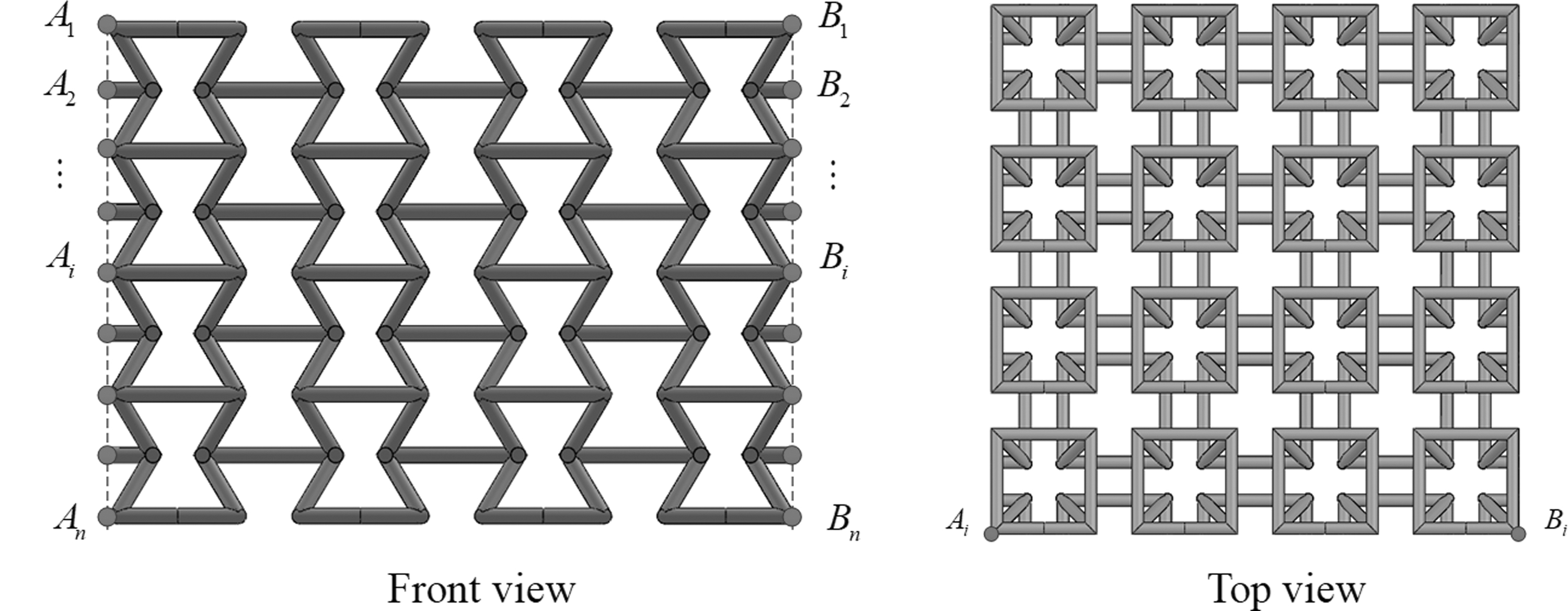
Reference points for the measurement of Poison's ratio for whole structure.
Relative density is an important structural characteristic that distinguishes a lattice structure from others, which is defined by
where
EA and SEA are two key characteristics that are used to evaluate the structure's EA capacity. The energy absorbed is determined under the force–displacement curve, which could be expressed as
where F is the instantaneous compression force, and l represents the compression displacement. Taking the mass of the structure into account, SEA could be defined. That is,
where M is the mass of the structure. Generally, SEA characterizes the EA efficiency of the structure. In other words, a lattice structure with a greater SEA can obtain a better EA efficiency.
Also, mean crushing force (MCF) under a certain compression displacement l is defined as
The maximum load during the quasi-static compression process is also an important indicator, which is denoted as peak crushing force (PCF). That is,
Sample Preparation and Compression Test
To study the compressive behavior of proposed 3D auxetic reentrant structure, the array structures with 4 × 4 × 4 assembling unit cells with different geometric parameters are built and compared. The CAD models of those structures are designed and produced using Autodesk Inventor 2021.
The material used in the fabrication of the specimens is 18Ni350 Maraging Steel alloy powder produced by Sandvik Osprey Ltd., of which the chemical composition is presented in Table 2. The 18Ni350 powder was produced by gas atomization with nitrogen, with the powder size distribution between 15 and 45 μm.
Chemical Composition of 18Ni350 Maraging Steel Powder (Supplied by Sandvik Osprey Ltd.)
The laser diffraction analysis indicated that the distribution is d10 = 18.9 μm, d50 = 29.9 μm, and d90 = 48.1 μm. As a new product from Sandvik Osprey Ltd., the exact material properties of specimens additive-manufactured by 18Ni350 powder are currently not available; we, hence, take general ranges of grade 350 maraging steel properties, 32 which are given in Table 3, as references tuning our FEA model in a later section.
Basic Mechanical Properties of Grade 350 Maraging Steel
The as-designed lattice samples are fabricated by the LPBF process using an EOS M290 system, which is equipped with a single 400 W Yb-fiber laser and focus diameter of 100 μm. The 4 × 4 × 4 lattice arrays are built with a strut thickness at 500 μm. As listed in Table 4, five designs with different cross-sections and reentrant angles are prepared.
Geometric Parameters of the Five Groups of Samples
All the samples are printed at a layer thickness of 40 μm, and with a range of laser power, scan speed, and hatch spacing, which are shown in Table 5. Note that energy density, ED, is a parameter that is determined by the other four printing parameters, that is,
Printing Parameters for the Fabricated Samples
Moreover, for Design No. 1, six sample sets with all the six configurations are used to investigate the effects of all printing configurations, especially at the small strain stage (<5%). It is noted that the configuration A (lower power and smaller hatching space) leads to obvious higher structural supporting stiffness, especially at the small strain stage as a preferred printing configuration, whereas at the large strain stage, similar mechanical responses with no sudden structural failure are observed for the samples prepared by both A and B printing configurations.
For other designs, three samples with A configurations are hence prepared to study the scanning speed and energy density effects on mechanical responses, especially at the large strain stage (>5%). The lattice samples are tested and evaluated in the as-built state, with no post-build thermal or surface post-processing after the printing.
The compression tests were conducted in accordance with Standard ASTMD1621 using an MTS 250 kN hydraulic testing machine. Figure 4 illustrates the compression process of the samples, which were compressed at a constant speed of 2 mm/min under room temperature. Throughout the test, the loading force and the longitudinal displacement of the tested sample were recorded. In addition, front images of the sample were captured using a camera positioned 30 cm away to measure the displacements of the reference points.
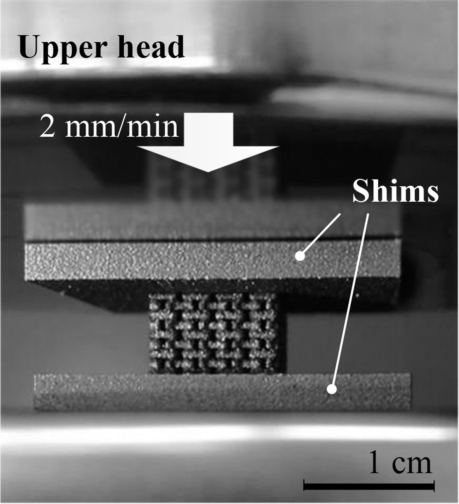
Quasi-static compression test setup.
By analyzing the acquired axial and transverse strains,
Results and Discussion
Effect of printing configurations
The quasi-static compression force-displacement curves for Design No. 1 with six different printing configurations are illustrated in Figure 5. It can be observed in the figure that the six curves show a little difference from one another. Compared with samples with B printing configurations, the A-series samples have larger equivalent elastic moduli.

Load-displacement curves of samples No. 1 with different printing configuration.
Referring to Table 5, we can see the A-series samples are printed with smaller hatch space. Moreover, for each A and B series, the samples with smaller scan speed exhibit higher yield strength.
To further gain an insight of the relationship between mechanical properties of the fabricated samples and different printing variables, the samples are analyzed by optical microscopy and compared. The printing quality of the samples is analyzed from two views—the front view and the top view (Fig. 6).
The microscopy directions for the samples: left—front view; right—top view.
The samples are cold mounted in resin and then ground and polished following standard metallurgical procedures. The images are captured using a ZEISS optical microscope, and the analysis is carried out with material modules available through ZEISS Zen Core software.
The software is used for automated measurement of the lattice features such as strut thickness and node circularity, as well as porosity within the struts. The comparison of the AM-printed samples with the as-designed CAD models is also performed via micro-CT.
Representative images of Design No. 1 samples are displayed in Figures 7 and 8. As we can see, the samples exhibit different porosity defect levels due to the different printing variables. Under the same energy density (scan speed), the samples with lower laser power and smaller hatch distance exhibit lower porosity.

Porosity of six samples from top views for Type No. 1.
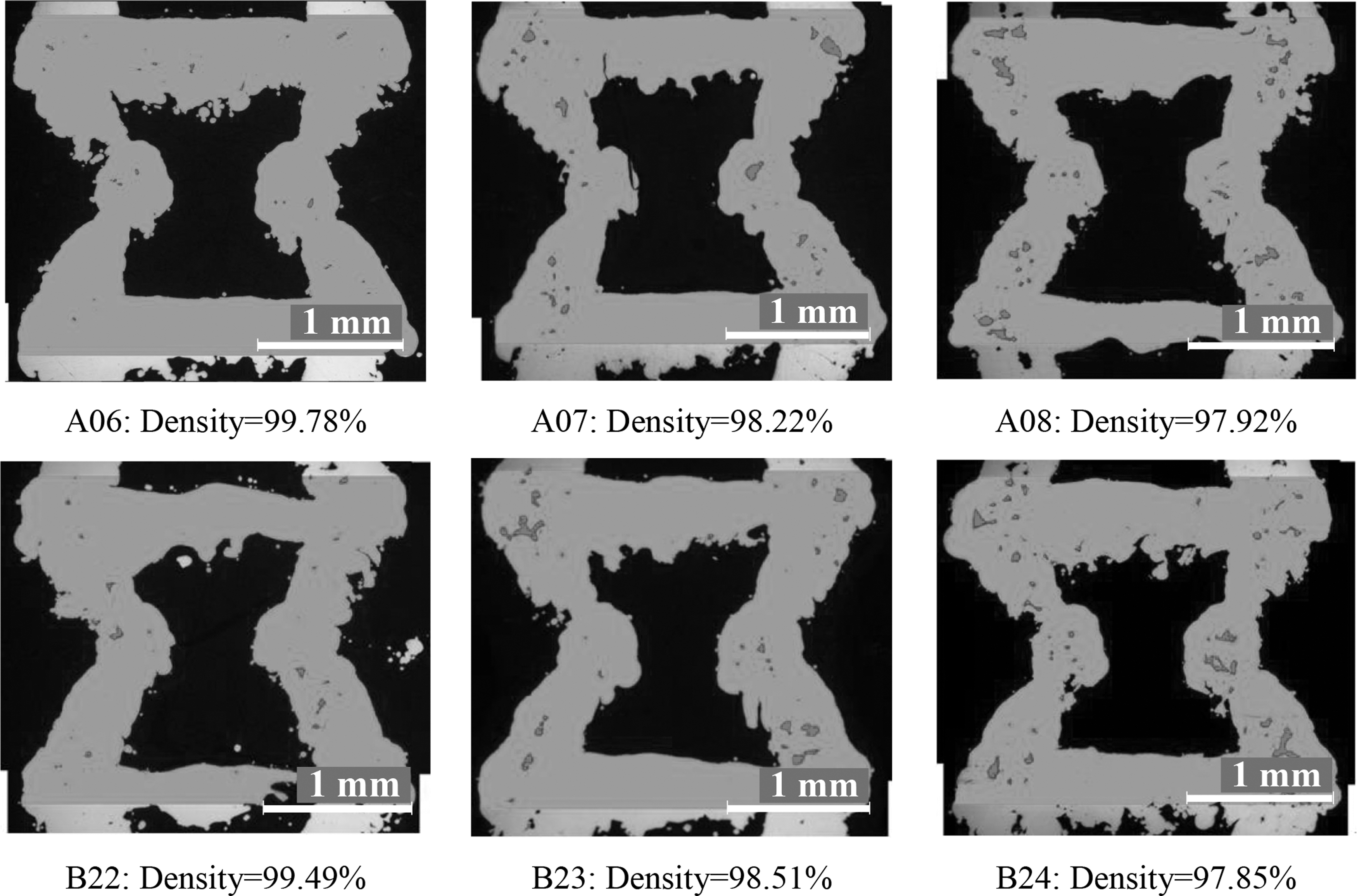
Porosity of six samples from front views for Type No. 1.
On the other hand, under the same laser power and hatch distance, the samples with higher scan speed (lower energy density) result in more incomplete printing (as shown in Fig. 8 B22), thus leading to a worse porosity condition.
Besides, some un-melted particles are observed on the surface of the struts, especially for the horizontal struts, which may lead to the discrepancies between fabricated and as-designed samples, as shown in Figure 9. As compared in Figure 8, the horizontal struts are obviously more uneven than the other parts. Due to these printing discrepancies, the structures perform with a weaker strength than expected, which will be seen in the material properties for the FE model in the following section.

Illustration of difference between as-designed sample (orange) and fabricated sample (gray), via micro-CT scanning. CT, computerized tomography.
Effect of geometry
As seen in Table 1, the proposed reentrant structure is geometrically defined by five independent parameters, of which the variation plays a critical role in the mechanical behaviors of the structure. To help optimal design in the future, it is necessary to analyze the effect of these geometric parameters. In addition to the experimental investigation, the FE model is built to help analyze the geometric effect of the structure.
According to the comparative result that A-series samples exhibit larger supporting stiffness and larger yield strength than B-series samples, so the samples for other four designs are only fabricated with A configurations to just compare the effects for different geometry parameters.
FE model
The constitutive relationship for the material in our FE model is described by the elasto-plastic model. As aforementioned, the mechanical properties of the material used in the FE model refer to Table 3. In some previous work, 33 the researchers used an equivalent cross-section or wall thickness based on the optical microscopy images to tune the FE model.
However, the change of the whole structure's geometry will affect the actual relative density of the proposed structure, thus resulting in a situation where the numerical model cannot well describe the densification period. On the other hand, it is very difficult to determine the weakest cross-section for the whole structure via optical microscopy images.
The exact defect sizes and locations in real samples are randomly generated and difficult to be precisely modeled. For the mechanical properties of 18Ni350 Maraging Steel, the Young's modulus, yield strength, and mass density are closely related with the manufacturing process, post-process, and printing defects.
The printing quality for the standard ASTM specimen is quite different from that of the lattice structure samples. Therefore, in this paper, Young's modulus of the material is adjusted to tune the FE model. There are more defects in the studied lattice samples, with reentrant diagonal struts affecting the structural mechanical performance.
And these effects can be simulated by assuming lower equivalent material modulus considering the defect areas that do not hold expected load. Specifically, the Young's modulus and yield strength of 18Ni350 Maraging Steel used in the FE model are adjusted as 40 GPa and 1680 MPa to compensate the difference between as-designed models and fabricated samples mentioned in the last section.
The values are determined by the verification result of design No. 1. After all the essential parameters for the FE model are determined for samples No. 1, the adjusted material parameters would be kept unchanged for the other structures with different geometry.
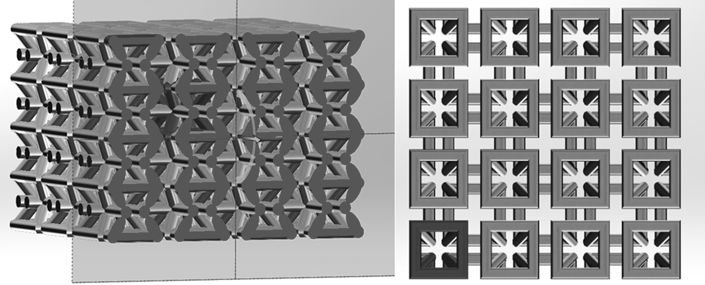
A tuned FE model is established using the commercial software ANSYS®. Noting that building a whole FE model to do the simulation costs too much time, the FE model is simplified as one-eighth of the whole structure, as illustrated in Figure 10.

FE model built for the structure.
Meanwhile, three symmetry boundary conditions are imposed to make the one-eighth model behave with a similar deformation with the whole structure. A rigid plate is added above the structure to simulate the moving head of the testing machine, moving downward to compress the structure. The structure is meshed with tetrahedral elements, while the rigid plate is meshed with rigid body elements.
Moreover, to avoid geometric interpenetration between the surfaces of the structure during the deformation, a frictional self-contact with 0.3 of empirical coefficient of friction is defined, which is an estimate parameter based on the empirical and testing data between steel surfaces. 34
Considering the trade-off between accuracy and computation time, the loading speed of the rigid plate is set as 2000 mm/s, where the resulting kinetic energy of the structure is close to zero (Fig. 11). That means the structure's internal energy is almost equal to the external workload, so the simulation under this loading speed can be regarded as a quasi-static analysis. 35
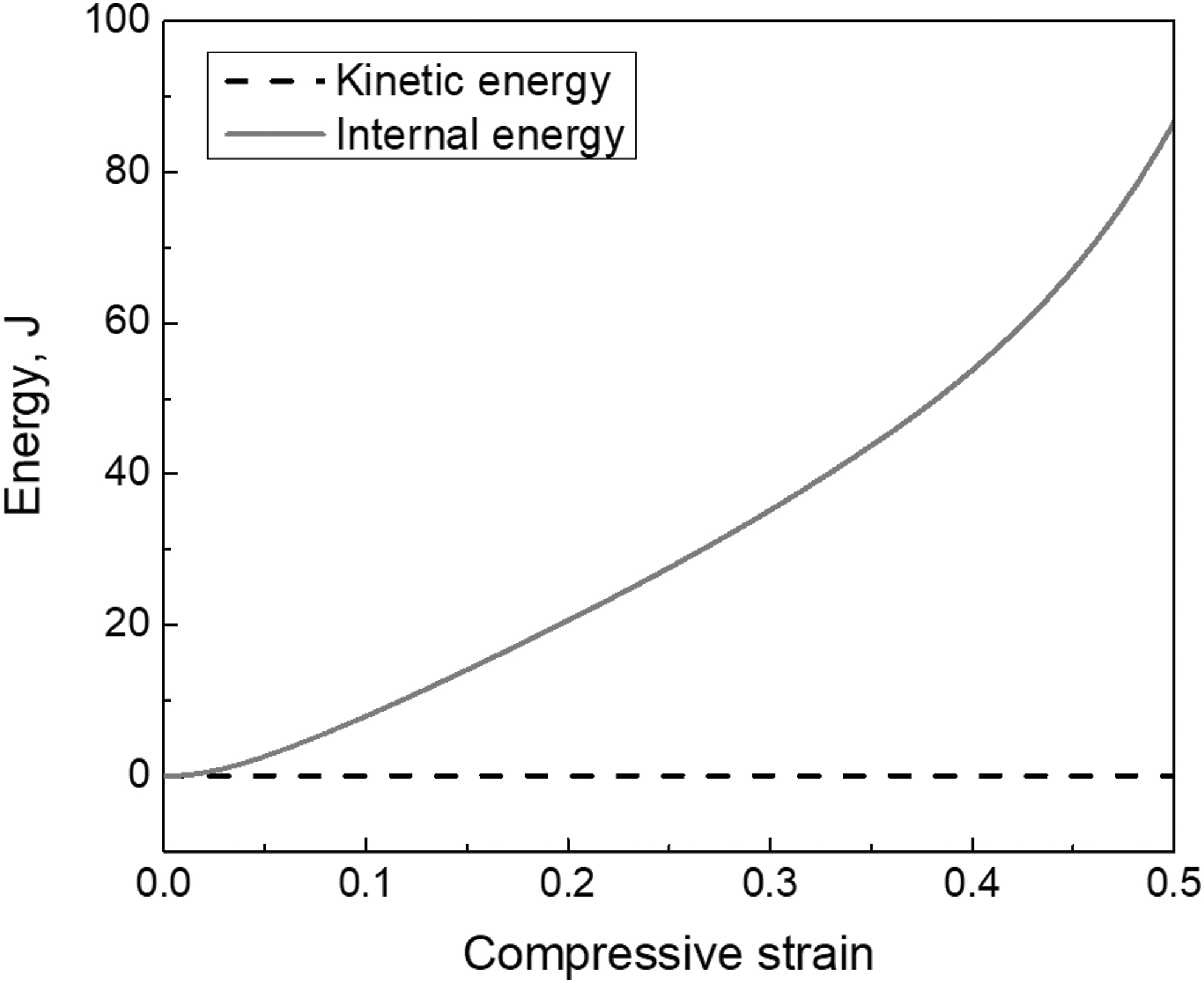
Internal energy and kinetic energy of Design No. 1 during the compression.
The mesh sensitivity is also studied to obtain the appropriate element size for the simulations, which finds that a maximum element size of 0.25 mm is sufficient to ensure convergence of numerical results. For example, in Figure 12, there is no significant change in the stress-strain curves for design No. 1 once the element size is reduced below 0.25 mm.
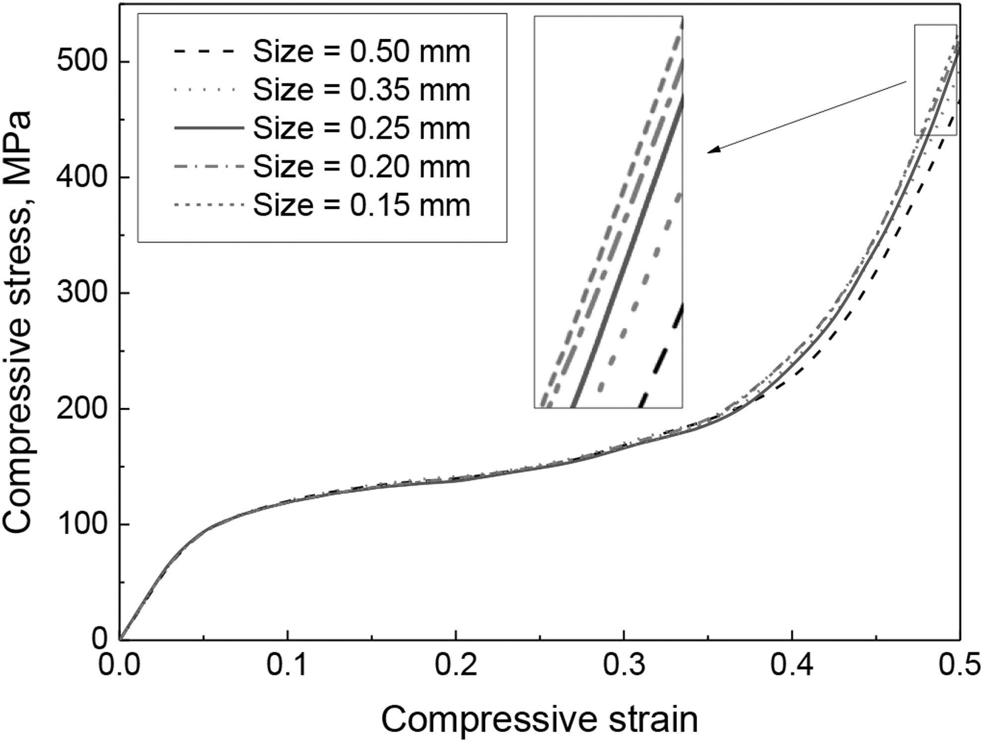
Mesh sensitivity study of stress-strain curves with different maximum element sizes for Design No. 1.
Therefore, the five structures are meshed with a maximum element size of 0.25 mm in the following numerical simulations. The detailed boundary conditions and meshing information are summarized in Table 6.
Applied Boundary Conditions and Meshing Information
Figure 13 shows numerical and experimental results of the stress-strain curves for Design No. 1. Based on the adjusted material parameters, the numerical stress-strain curve is fitted to the corresponding experimental curves. By observing the stress-strain curves, the deformation of the proposed auxetic structure can be divided into three periods, that is, (1) Elastic deformation period, (2) Plateau deformation period, and (3) Structure densification.

Experimental and numerical stress-strain curves of the samples.
It can be found that the numerical curve did not agree with the experimental curves very well at the densification period. On the one hand, the three experimental curves are obtained from the three specimens fabricated with different printing parameters, but the numerical model cannot reflect the difference of the printing parameters.
On the other hand, the specimens have many defects, whereas the numerical model is a perfect CAD model. So, we can observe that the slopes of the experimental curves are obviously lower than that of the numerical curve at the densification period. Moreover, Figure 14 presents the comparison between experimental and numerical deformation for Design No. 1 at compressive strain ɛ = 0, 0.2 and 0.4.
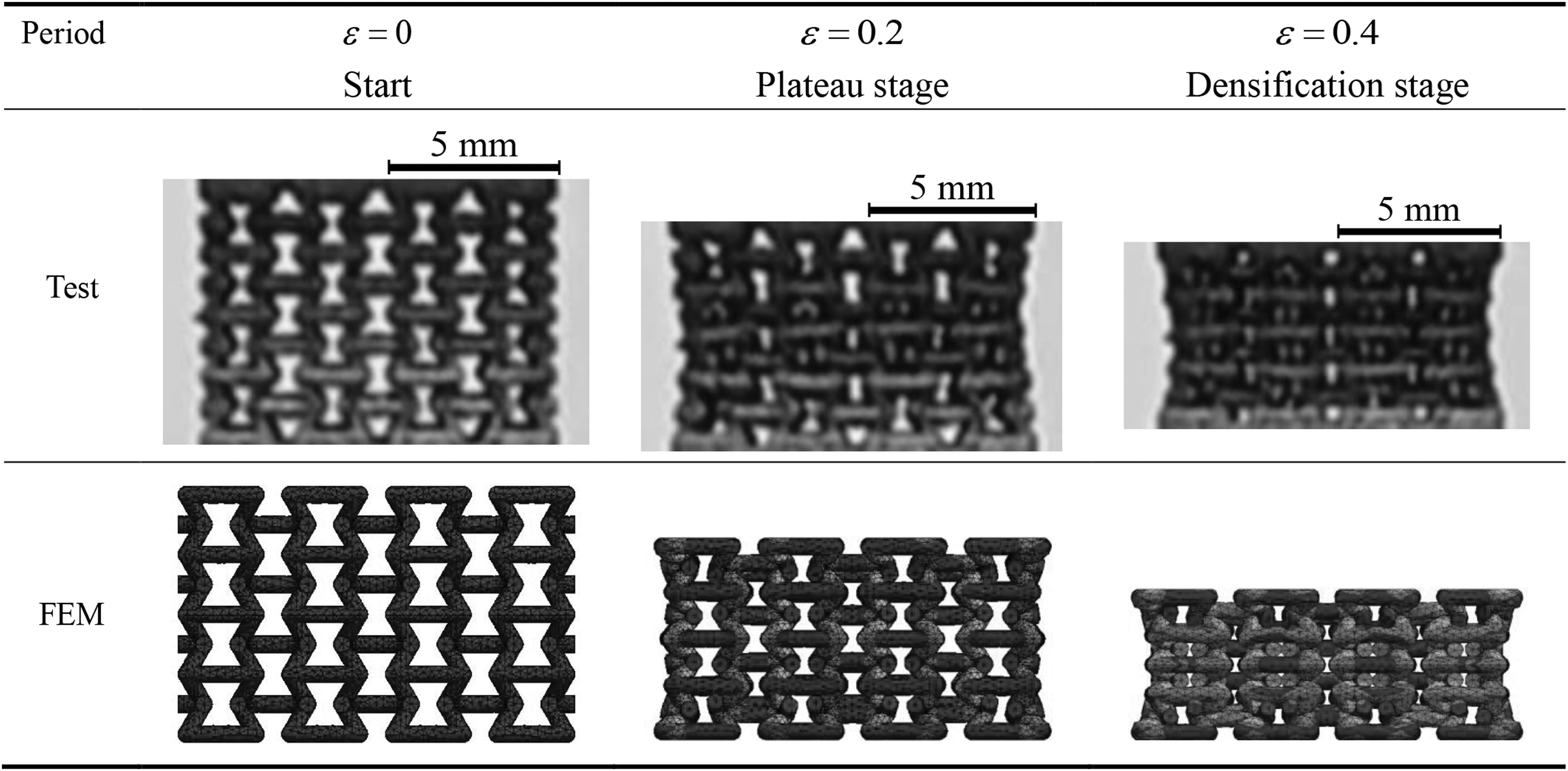
Comparison of deformation for Design No. 1 through experiment and simulation results.
As we can see, the structure shrinks in the transverse direction and exhibits NPR behavior during the compressive deformation. In the following sections, the parametric analysis is conducted to study the effects of geometric parameters on the compressive behaviors of the proposed structure with the assistance of this FE model.
Effect of reentrant angle
The reentrant angle,

Effect of reentrant angle.
It should be noted that Design No. 5
Therefore, similar to the behaviors of regular lattice structures, the stress-strain curve for Design No. 5 exhibits a drop with the structure reaching failure/buckling point and then holds a long plateau period. The phenomenon is not desirable for structural protection and EA. When it comes to SEA (Fig. 15d), the Design No. 5 with
However, in the late period, for example, when the strain exceeds 0.45, the Design No. 5 loses the advantage, whereas the designs with NPR effect exhibit densification and enhance the stiffness and strength. But it should be noted that not all the structures with smaller than
The reason is that the structure with a large
As we can see, with the same total height, the structure with smaller
However, with the compression continuing and getting through the transition points at large strain (>0.4), the structure with smaller
Effect of cross-section
The cross-section with different shape (No. 1 and No. 3) and area (No. 1 and No. 4) is a parameter that directly affects the relative stiffness of the structure. In Figure 16, the compressive properties of the structures with circle and square, and the structures with different cross-sectional area are respectively compared.
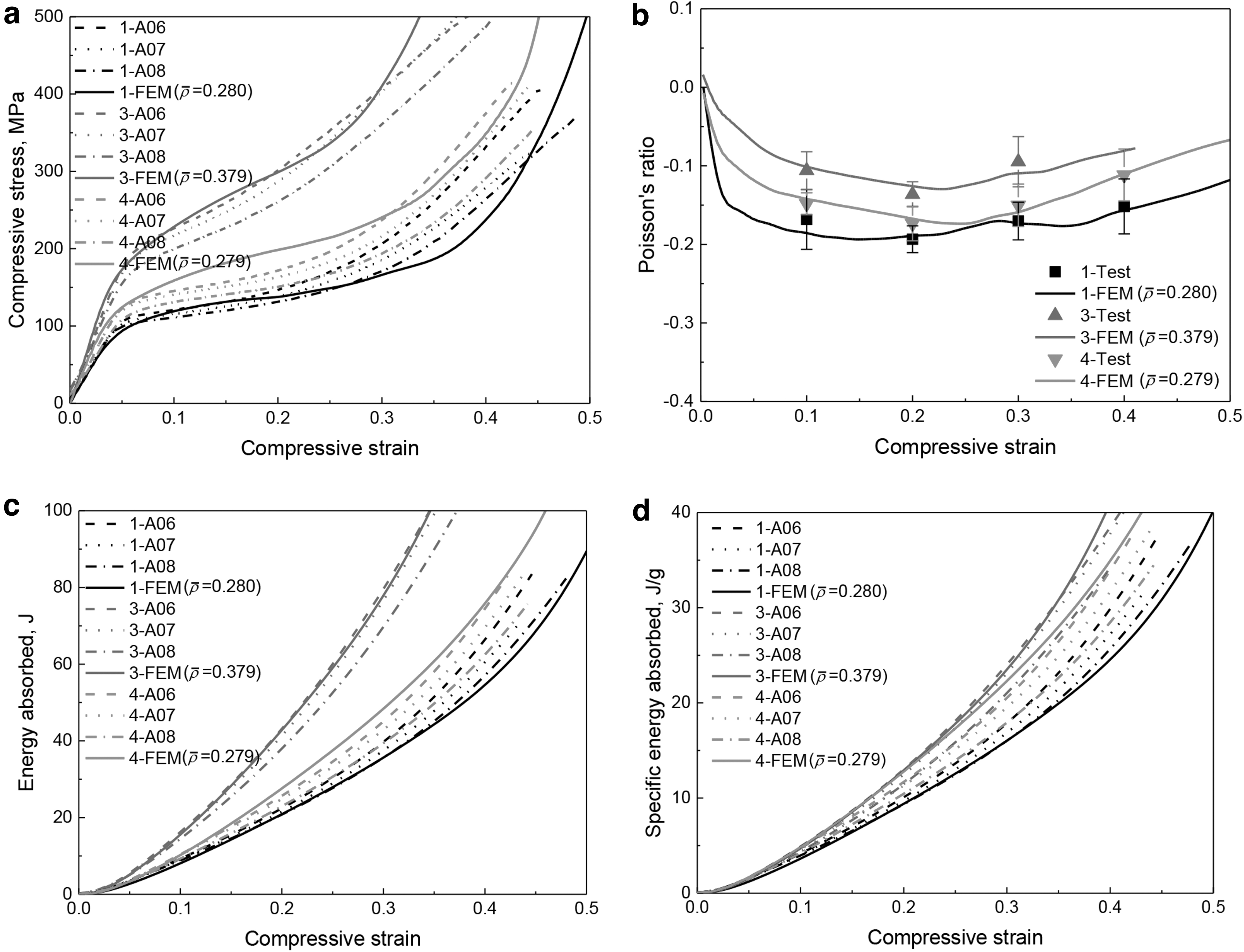
Effect of cross-section.
It is interesting that with the same cross-sectional area, the structure with square cross-section (Design No. 4) obtains a larger stiffness and yield strength than that with circle cross-section (Design No. 1). Although the NPR effect of Design 4 is less obvious than that of Design 1, the SEA curve of Design 4 shows a larger value than that of Design 1.
In addition to the cross-sectional shape, the cross-sectional area of the struts plays a more critical part in the compressive properties of the structure. The diameter of the cross-section for Design 3 is twice of that for Design 1. As we can see in Figure 16, the increase in the cross-sectional area makes the structure stronger in stiffness, strength, and SEA, but increases the relative density, thus decreasing the space for buffering.
Comparing the stress-strain curves between Design 1 and Design 3, we can find that the MCF and PCF of the Design 3 is larger than that of Design 1. This means that the structure with larger cross-sectional area has to resist larger crushing force. In armor design, MCF and PCF are also critical factors to be considered.
As we can see, using the square cross-section and increasing the diameter significantly increases the EA capacity, even though it reduces the effect of NPR and increases the relative density. However, the increase of cross-sectional area should be controlled considering the geometry limit and PCF.
Summary and Conclusions
A modified 3D reentrant lattice structure extended from the traditional 2D reentrant honeycomb structure is proposed, fabricated, and tested to study the design and printing parameters effects on its mechanical responses. LPBF is used to fabricate five groups of 18Ni350 Maraging Steel samples with different design parameters and printing configurations.
The quasi-static compression experimental investigations are then conducted. A tuned FE model is also built to simulate the compressive deformation of the proposed structure. The effect of dimensional errors between the AM-built structures and the as-designed ones is taken into account in the FE model.
The experimental results confirm the effect of scan speed and hatch distance on the printing quality and the corresponding compressive performances of the samples. Finally, with the assistance of FE analysis, parametric analysis is conducted to investigate the effect of design parameters, including reentrant angle, strut cross-section, on the compressive property of the structure.
The following results are obtained: (1) smaller hatch distance and scan speed can lead to less porosity level and more complete printing, resulting in larger stiffness and yield strength of the structure; (2) the structure with
The proposed reentrant auxetic structure presents a bright prospect for use as energy absorber in related engineering applications, such as light-weight vehicle bumper and helmets. And the parametric study results indicate a promising design direction of such metamaterials with better EA capacity.
In future studies, the investigations will be extended to analyze the mechanical behaviors of the structures under high-speed impact with different strain rates. To date, the proposed lattice structure has been assembled with the structure layers into a whole armor structure, which will also be conducted in bullet penetration tests. Moreover, an optimization procedure based on the Bayesian regularized neural network is planned to find the optimum geometries in terms of crashworthiness and EA capabilities.
Footnotes
Authors' Contributions
S.W.: Conceptualization, Methodology, and Writing—Original Draft. C.D.: Writing—Reviewing and Editing, Supervision. O.O.: Project administration, Funding acquisition, and Supervision. B.A.: Resources. J.K.: Resources. N.W.: Conceptualization, Writing—Reviewing and Editing, and Supervision.
Author Disclosure Statement
No competing financial interests exist.
Funding Information
The authors acknowledge funding from the Department of National Defence's Innovation for Defence Excellence and Security (IDEaS) Program in support of this project.