
Abstract
Abstract
The large amount of unfused powder that remains on the surface of Ti6AL4V porous scaffolds prepared by selective laser melting technology is a common problem. Therefore, this article investigated the effects of three different chemical polishing processes on the surface state, pore structure, and mechanical properties of small pore size scaffold materials at different polishing times in the field of implantable medical devices. The results show that the overall treatment effect of the simple chemical polishing process is poor, the internal treatment depth of porous support is insufficient and uneven, and the overall mechanical properties of the sample with the same porosity are average. The outer structure during the electrochemical polishing process showed an obvious treatment effect. However, the internal treatment depth and uniformity were significantly lower compared with the simple chemical polishing process, and the overall mechanical properties of the sample with the same porosity were inferior. The overall treatment effect, depth, and uniformity of the inner and outer structure of the sample using a dynamic chemical polishing process were significantly optimized, and the overall mechanical properties of the sample with the same porosity were superior to the other two methods. Furthermore, the main reasons for the nonuniform treatment effect between the inner and outer layers during the chemical polishing of porous scaffolds were observed to be related to the restricted exchange of etchant caused by the complex internal structure of porous scaffolds and the gas generated by the chemical reaction.
Introduction
Ti6Al4V
However, the clinical application of Ti6Al4V comes also with limitations. The material is still restricted by its forming process and structural design. Due to the basic characteristics of powder-bed laser forming process, many incompletely melted powdered particles adhere to the surface, and this surface defect leads to limited cleaning and sterilization effect of the products. Finally, it is the main cause of inflammation, bone resorption, and even implant loosening after implantation.5,6 Therefore, the removal of unfused powder particles from the surface of porous scaffolds is crucial to the further optimization of the material for medical needs.7–10
Due to technological limitations, the currently used metal surface treatment process is unsuitable for small-sized porous stents commonly used in the field of implantable medical devices. Traditional abrasive flow finishing or shot peening techniques are characteristic samples of these limited technologies.11,12 The inability of abrasive media to enter the interior of the porous support pore structure makes this type of technique ineffective in treating the inner surface of the porous support structure. In contrast, chemical polishing based on etchant etching is one of the most suitable and cost-effective methods for surface treatment of porous scaffold materials, as its treatment medium is an acidic solution that can reach deeply into the porous support to treat the surface of deep pore structures.8–14
It has been reported that pure chemical polishing can remove some of the unfused powder from the surface of porous scaffolds. Nevertheless, chemical polishing has limited ability to penetrate the interior of porous stents, which is not treated effectively. To improve the surface quality as well as the processing efficiency of the treated porous scaffolds, Tyagi et al. 15 introduced an electrochemical process, which can produce a smoother surface compared to the simple chemical polishing process. Nevertheless, the treatment effect uniformity is inferior to the pure chemical polishing when treating sample parts with complex internal structures. In contrast, Soro et al. 16 treated porous scaffolds using dynamic chemical polishing, aiming to improve their penetration inside the porous scaffolds through sufficient etchant flow.
Analysis of the existing literature showed that the majority of studies on the surface treatment of porous scaffolds with chemical polishing has focused on the simple evaluation of the surface treatment effect of large-size porous stents. In other words, the analysis of the difference between the inner and outer treatment effect of small-size porous stents and the comprehensive evaluation of the mechanical properties of samples remain very limited in the field of implantable medical devices. Moreover, no further analysis on the mechanism of many issues in the chemical polishing process of porous stents has been conducted, and the conclusions obtained do not provide clear guidance for the post-treatment process in the production of actual implantable medical devices.
In this study, three different chemical polishing processes were implemented to treat Ti-6Al-4V porous scaffolds fabricated by SLM technology, and the removal effect, treatment depth, uniformity, structural damage, and overall mechanical properties of the residual powder on the surface were evaluated under different treatment processes and times. On this basis, the phenomena occurring during the treatment of porous scaffolds by different chemical polishing processes were further analyzed and their specific mechanisms were discussed in depth to provide a theoretical basis for the industrial application and technological improvement of the surface treatment process of porous titanium alloy scaffolds.
Materials and Methods
Fabrication procedure
In this study, the scanning electron microscope (SEM) morphology of the TC4 powder is shown in Figure 1. Ti6Al4V spherical powder (1545 lm; Optimal Material Technology Co. Ltd., China) was used to fabricate porous support specimens by SLM (Dimetal 280; Laseradd Technology Guangzhou Co., Ltd., China) (Fig. 2). The entire porous scaffold is cylindrical (φ 12 × L18 mm), and it adopts the cuboctahedron pore structure, with pore diameter A of 900 μm, pore diameter B of 480 μm, pore throat diameter A of 370 μm, pore throat diameter B of 140 μm, and rod diameter of 250 μm.
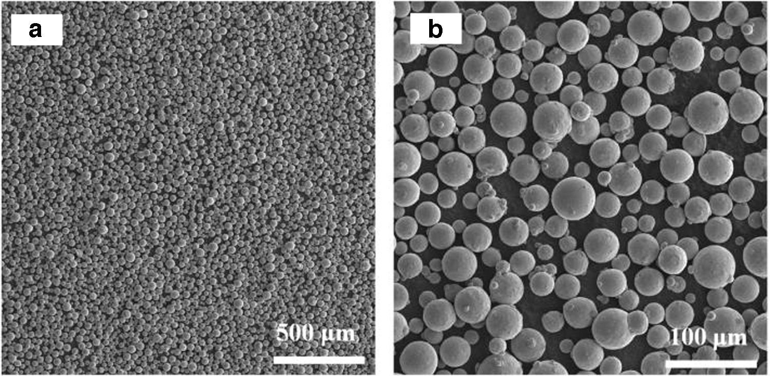
SEM image showing
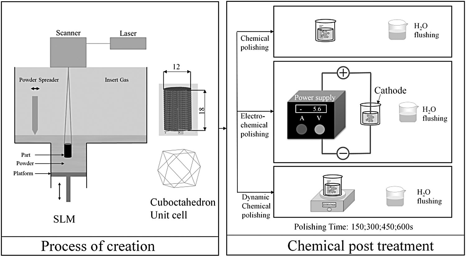
Schematic illustration of the fabrication procedure of Ti6Al4V scaffolds, chemical etching, and experimental procedure.
The process parameters obtained after preliminary experiments for optimization were as follows: scanning speed 1000 mm/s, laser power 175 W, scanning interval 60 μm, thickness 30 μm, and scan angle of rotation (θ) 67°. The sample was annealed following preparation in a vacuum annealing furnace (NB280M; Suzhou Norman Bill Material Technology Co., Ltd., China) at 850°C/2 h with cooling.
Postprocessing
The scaffolds were placed in 50 mL of an etchant containing 3.3% HF (50%), 11.1% HNO3 (70%), and 85.6% distilled water. This ratio is close to what is reported in the literature for titanium alloys.8,17,18 The scaffolds were chemically polished (CP), electrochemically polished (ECP), and dynamically chemically polished (DCP) with time gradients of 150, 300, 450, and 600 s for each method, respectively. The etching was performed at room temperature with the sample being completely submerged in the etching solution and the upward and downward directions during the sample processing were marked. Following the etching processing, the samples were rinsed thrice with fresh distilled water and dried for subsequent testing.
Scaffold characterization
Discontinuous mass tests on porous scaffold samples were performed thrice using an analytical balance (FA2004; Shanghai Lichen Bangxi Instrument Technology Co., Ltd., China) to calculate the porosity of porous scaffolds under different treatment processes as well as treatment times. To quantify the removal of powder particles from the porous scaffold, the lower surface of the upper half of the scaffold at 50% of the printing direction was used as a cross-section for image analysis. The lower surface of the upper half of the scaffold at 50% of the printing direction was observed with a digital display electron microscope (Shenzhen Osmio Optical Instruments Co., Ltd., China).
The graphical processing software Image J (National Institutes of Health, USA) was used to calculate the cross-sectional area of pore A before and after processing. The measurement field of view and area division are shown in Figure 3a. The schematic diagram of pore A is shown in Figure 3c. A SEM (MAIA3; TESCAN Brno, Czech Republic) was used to examine the microscopic morphology of the lower surface of the upper half of the porous scaffold at 50% of the printing direction. Static uniaxial compression tests on the porous bracket samples were performed according to ISO 13314:2011 standard using an electronic universal testing machine E43 (MTS Systems, USA).

Schematic diagram of the division of the lower outer lower surface of the upper half of the porous scaffold at 50% of the printing direction.
The load displacement data were recorded during compression at a constant deformation rate of 2 mm/min to plot the stress-strain curve, and to calculate the maximum compressive strength of the material for data analysis. The dynamic uniaxial compression test was performed on the porous bracket samples using a dynamic magnetic mechanical test system (Electroforce 3510; TA Instruments, USA), and 3391 N (60% of the maximum force of the sample before treatment) was applied to each sample during the test. 19 All sample characterizations and testing were repeated thrice to ensure the representativeness of the result data.
Results
Porosity
Figure 4 shows the trend and specific data of the porosity of samples under different treatment processes and times before and after treatment. The results show that with the increase in treatment time, the porosity of samples after each process increases considerably. The porosity of samples after ECP increases the most in the same treatment time among the three different treatments, followed by DCP and by simple CP. The porosity of the sample parts after each process treatment surpassed the theoretical porosity limit of the stent (78.5%) after 300–600-s treatment, respectively, and the possibility of structural damage appeared.
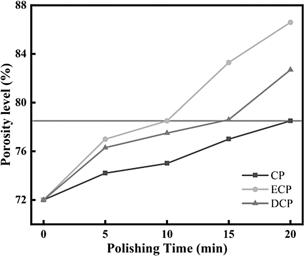
The change trend of porosity of the sample before and after treatment. The gray reference line is the design value of porosity of the sample (78.5%).
Processing depth
Figure 5 shows representative images of the cross-section of the upper half of the 50% height of the porous support sample under different treatment processes and times. The standard line was drawn with the average value of pore A cross-sectional area (0.95 mm2) of the porous scaffold under the optimal treatment effect. Figure 5 demonstrates that the standard line of each group gradually moved to the center of the pore structure as treatment time increased, and in the case of the pure CP group, it remained in the outer pore after 600 s of treatment.
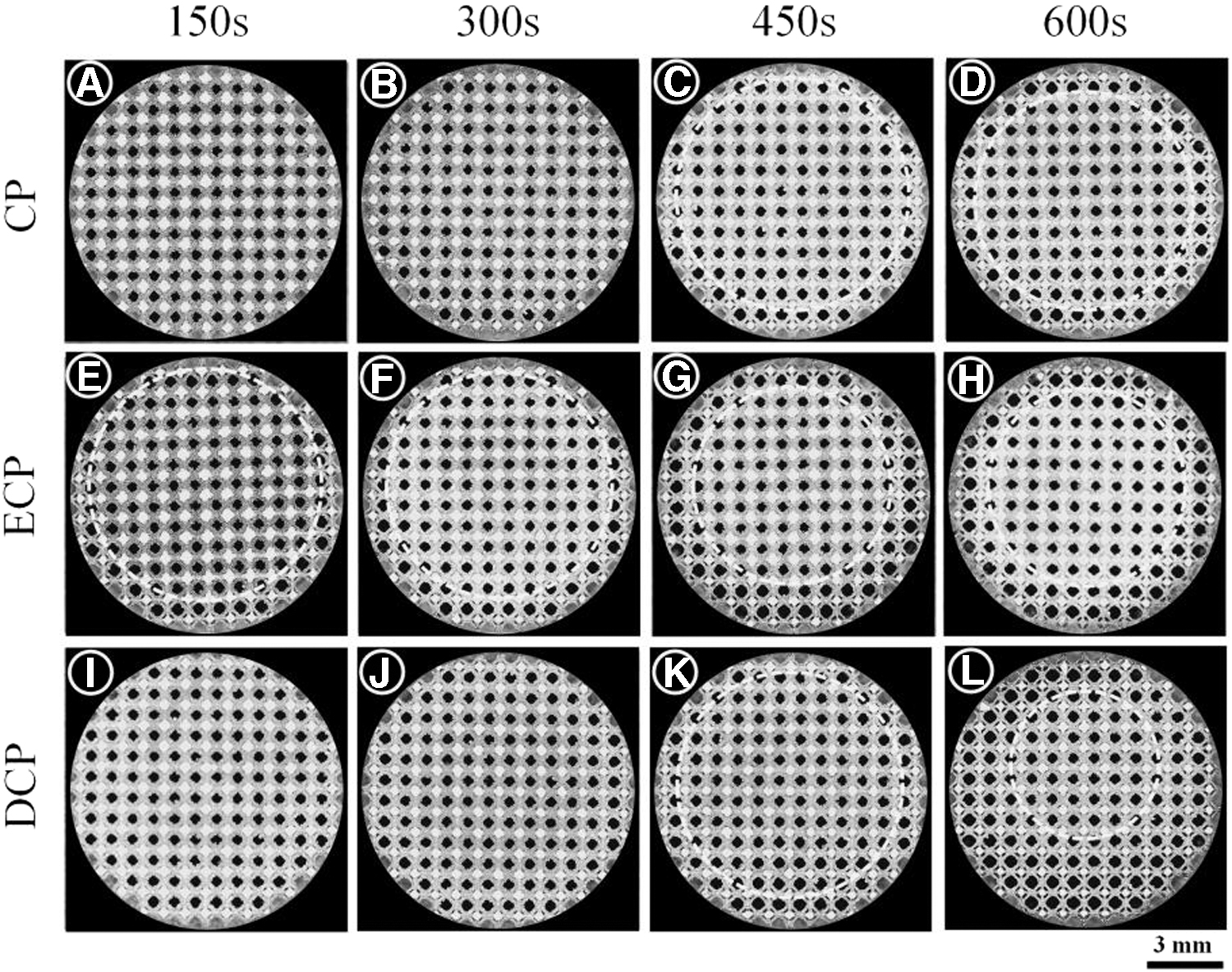
Standard lines for the general shape and treatment depth of the cross-section of the upper half of the 50% height of all samples at different polishing times.
The standard line of the ECP group was also located in the outer pore. The DCP line was located in the outer pore above the sample, while the lower end was located in the inner pore. The standard lines of all the above groups showed a gradual movement of the center of the circle to the upper part of the section.
Homogeneity of polishing
The area of pore A of four pore units in each row from the top to the bottom of the upper and lower axes of the porous scaffold sample was counted, based on the cross-sectional image analysis of the upper half of the 50% height of the porous scaffold sample. Figure 6 shows the hole A area data for different treatment processes, times, and regions. The data variation curves were also fitted by a polynomial through the average of each data set. The trend of the fitted curves showed a U-shaped depression with increasing treatment time, and the lowest point of the curve was basically biased upward.
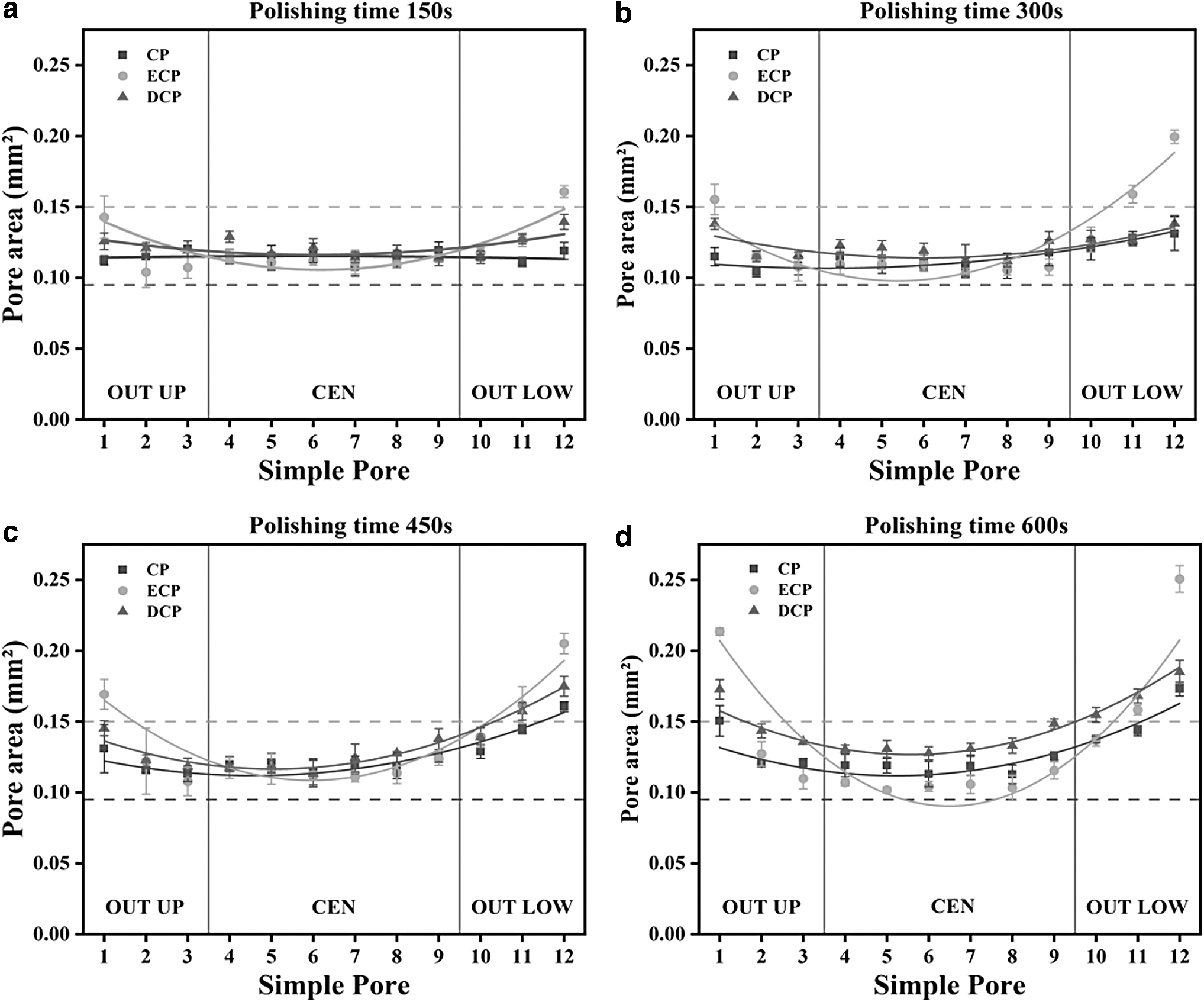
Statistics and trend fitting of the area of cross-sectional pore A in the upper half of 50% height of the sample before and after treatment;
The degree of concavity of fitted curves in the ECP group was considerably larger than that in the other two groups, while the degree of concavity of fitted curves in the other two groups was basically similar. The fitted curves of the DCP group were relatively upper in general. The data statistics revealed that the overall mean and standard deviation of the pore A area of porous scaffolds in each group gradually increased with increasing treatment time. The overall data mean of the DCP group was greater than the other two groups, and their standard deviations were lower than the other two groups.
Simultaneously, the analysis of the pore A cross-sectional area data of each row in different regions showed notable differences between the inner and outer layers. This phenomenon was especially pronounced in the ECP, where the difference between the pore A cross-sectional area of the outer and inner pores reached 13–56%, and the difference gradually increased with the treatment time.
Morphology of scaffolds
The microscopic morphology of the cross-section of the upper half of 50% height of the porous scaffold sample before and after each treatment was examined. Figure 7 shows the typical microstructure of the pore structure before the polishing treatment. The microstructure of the pore structure in the OUT UP, CEN, and OUT LOW regions remained basically identical, a large number of unfused powder particles of different sizes adhered to the surface of the stent in each region, the base structure of the stent is not visible, and the actual measurement of the rod diameter of the stent was considerably larger than the design value.
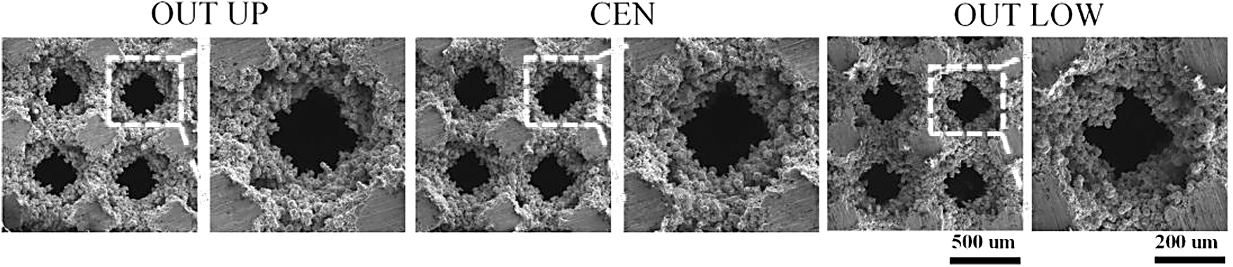
SEM image of a cross-section of an untreated titanium scaffold.
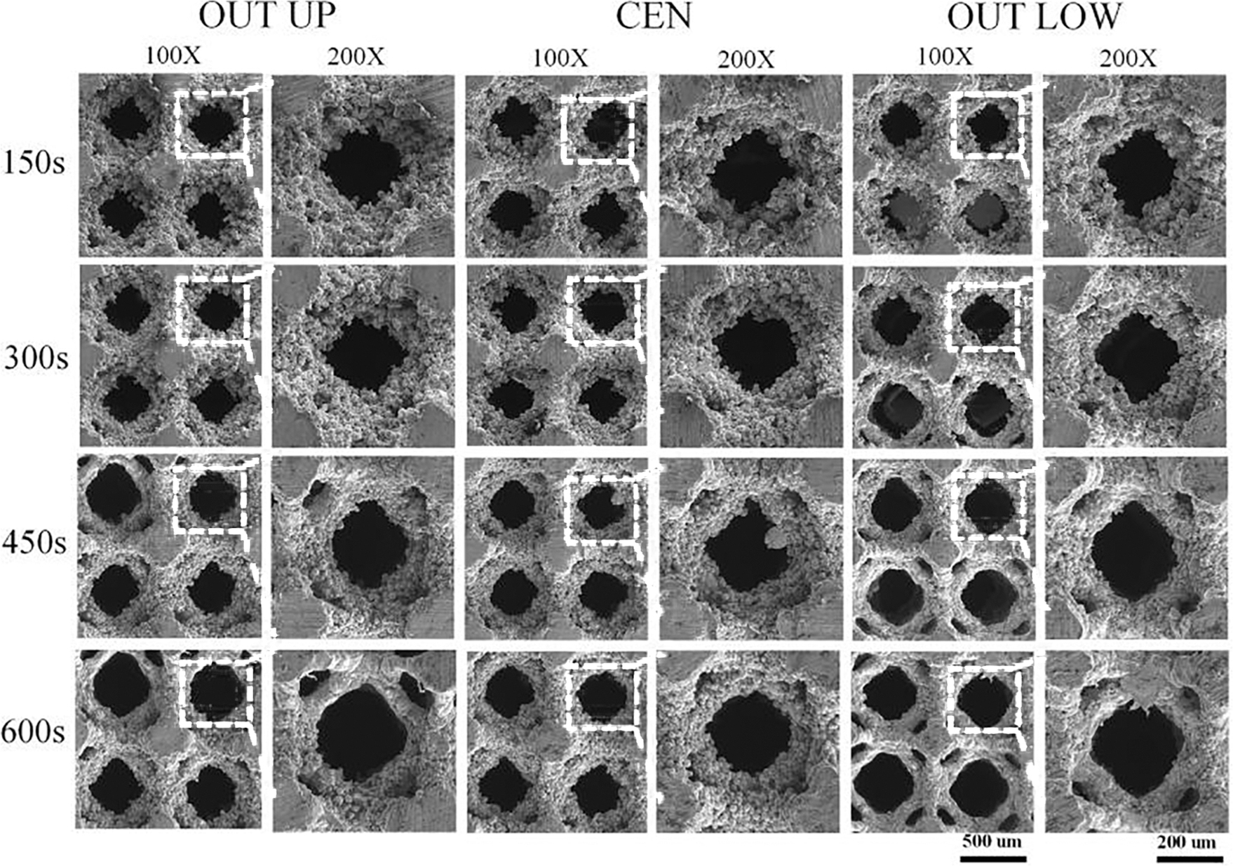
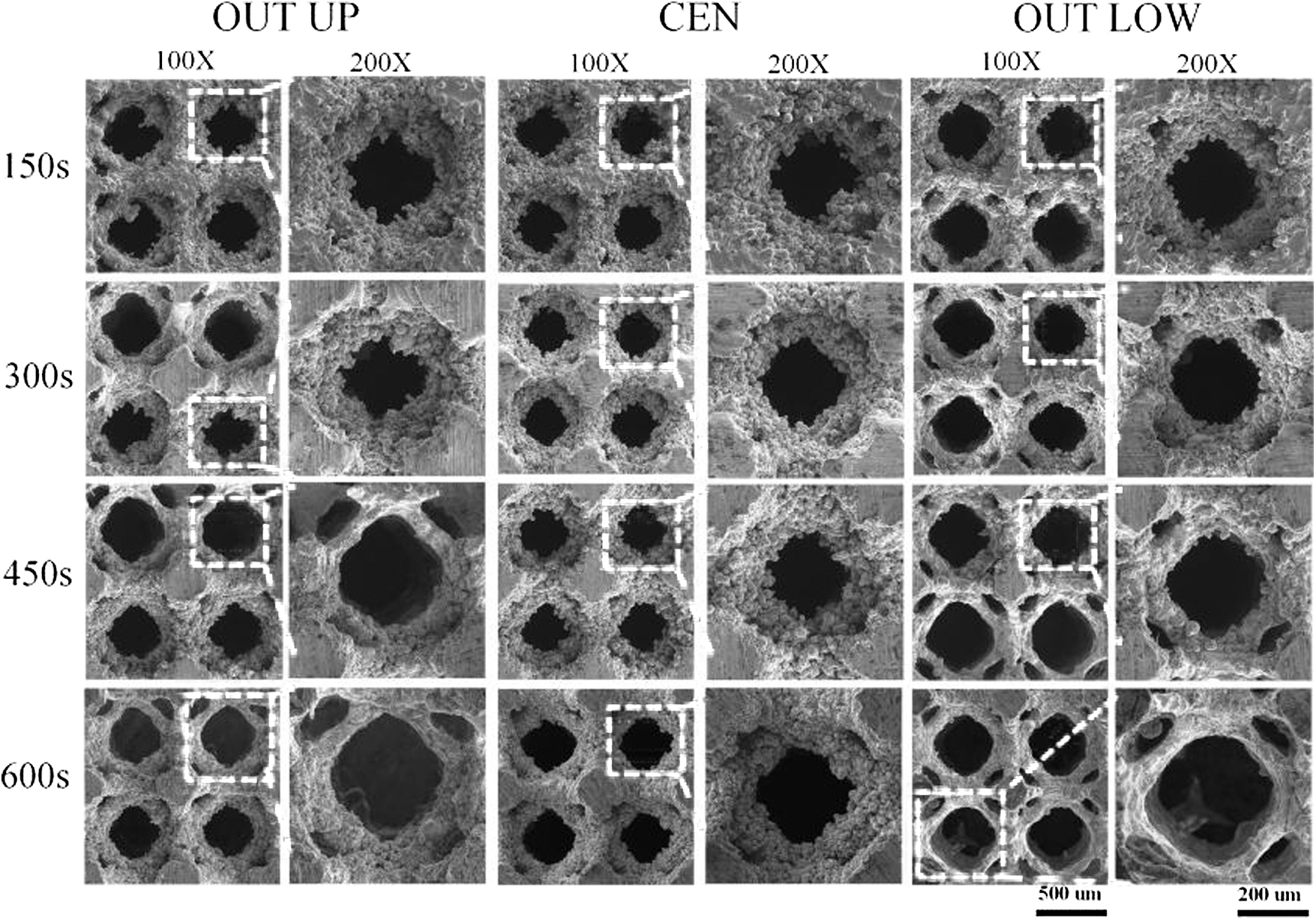
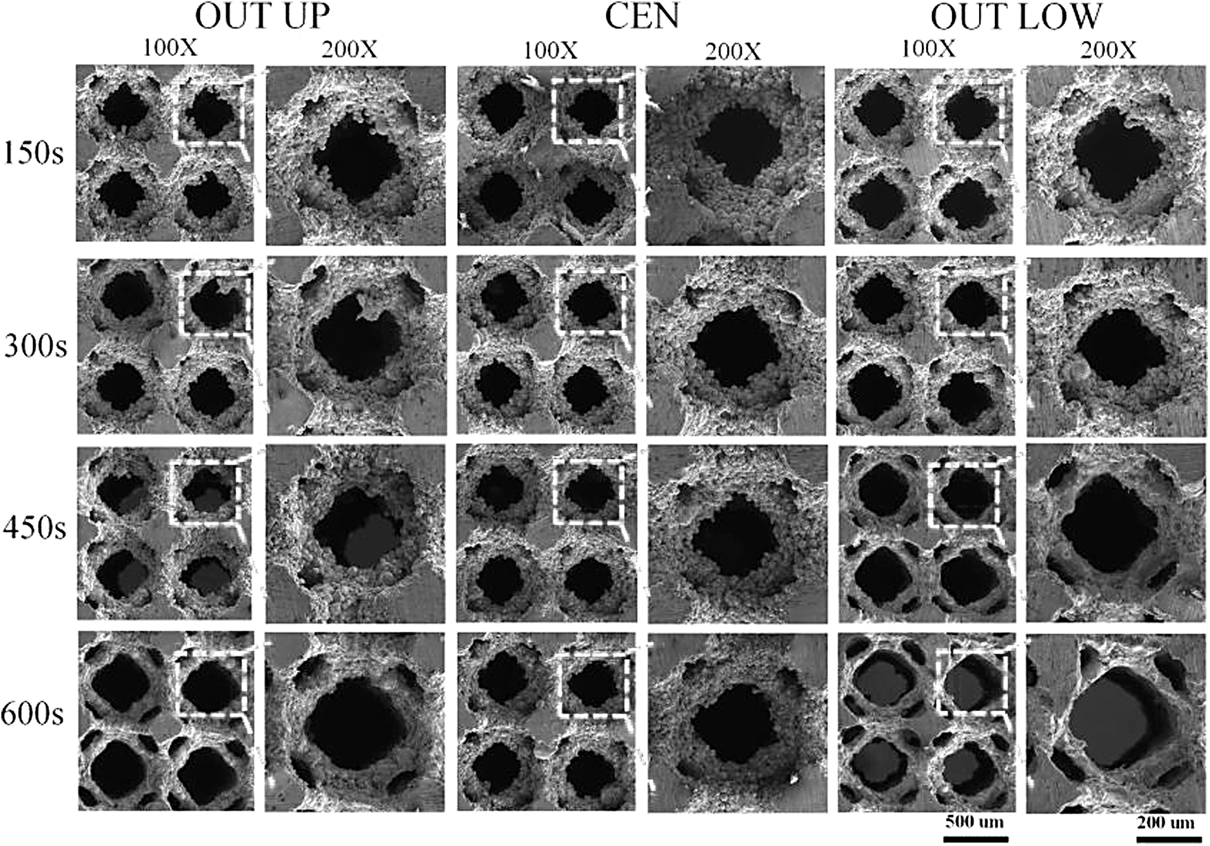
Figures 8–10 show the microscopic morphology of the pore structure in the OUT UP, CEN, and OUT LOW regions at different treatment times for CP, ECP, and DCP. The pore structure of each group showed a general pattern in which the unfused powder on the surface of the scaffold was steadily reduced with the increase in polishing treatment time.
SEM image of a titanium alloy scaffold after chemical polishing.
SEM image of a titanium alloy scaffold after electrochemical polishing.
SEM image of a titanium alloy bracket after dynamic chemical polishing.
Comparison of surface states of scaffolds in different areas after different treatment processes and different treatment times showed clear differences in the surface treatment effects between the inner and outer scaffolds in each group, which gradually increased with the increase in treatment time. The differences were the largest in the ECP group and the smallest in the DCP group, respectively. In addition, with the same treatment process and time, the stent surface treatment effect in the OUT LOW area of samples was more pronounced than that in the OUT UP area, and the stent base structure was destroyed more quickly.
With the increase in CP treatment time, there was no obvious change in each area for 150 s of treatment time. When the sample was treated for 300 s, the small particles of powder on the surface of the scaffold in the OUT LOW area were partially removed. However, many large particles of powder remained, and the base structure of the scaffold linkage was not revealed, while no obvious change was observed in the OUT UP and CEN areas. When the sample was treated for 450 s, fewer large particles of powder remained on the surface of the local bracket in the OUT UP and OUT LOW areas, and part of the bracket connecting the rod base structure was revealed.
At this time, the small powder particles on the surface of the stent in the CEN area were basically removed, but many large particles of powder residue remained, and the base structure of the stent linkage remained occluded. When the sample was treated for 600 s, some powder on the surface of the stent linkage in the OUT UP and OUT LOW areas was basically removed and most of the base structure of the stent linkage was revealed, but the state of the surface of the stent linkage in the CEN area was still not notably changed compared with that before.
In the case of ECP, when the sample was treated for 150 s, the small powder particles on the surface of the scaffold in the OUTER LOWER area were partially removed, but much large powder residue was still present, and the base structure of the scaffold linkage remained occluded, while there was still no obvious change in the OUT UP and CEN areas. When the sample was treated for 300 s, only few large powder particles remained on the surface of the local bracket in the OUT UP and OUT LOW area, and part of the base structure of the bracket connecting rod was revealed. The small particles of powder on the surface of the bracket in the CEN area were basically cleared, but many large powder particles remained, and the base structure of the bracket connecting rod was not revealed.
When the sample was treated for 450 s, most of the powder on the surface of the stent in the OUT UP and OUT LOW areas was removed, and part of the stent base structure was damaged, but the surface state of the stent connecting rod in the CEN area remained similar as before. When the sample was treated for 600 s, all the powder on the surface of the bracket in the OUT UP and OUT LOW areas was removed, most of the bracket base structure was damaged, and a few bracket connecting rods were almost fractured. Only small powder particles were removed from the surface of the bracket in the CEN area, many large particles remained, and the base structure of the bracket connecting rods remained occluded.
In the case of DCP, when the sample was treated for 150 s, the small powder particles on the surface of the scaffold in the OUT LOW area were partially removed, but much large particle powder residue was still present, and the base structure of the scaffold remained occluded, while there was still no obvious change in the OUT UP and CEN areas. When the sample was treated for 300 s, only few large powder particles remained on the surface of the local brackets in the OUT UP and OUT LOW areas.
Part of the bracket connecting rod base structure was revealed, while the small powder particles on the surface of the brackets in the CEN area were basically cleared, but many large powder particles remained, and the bracket connecting rod base structure was not revealed. When the sample was treated for 450 s, most of the powder on the surface of the stent in the OUT UP and OUT LOW area was removed and the base structure of the stent was revealed, while the surface state of the stent in the CEN area remained almost the same as before.
When the sample was treated for 600 s, all the powder on the surface of the bracket in the OUT UP and OUT LOW areas was removed and most of the bracket base structure was damaged. Some large powder particles remained on the surface of the bracket in the CEN area and the bracket connecting rod base structure was partially revealed.
Mechanical characterization
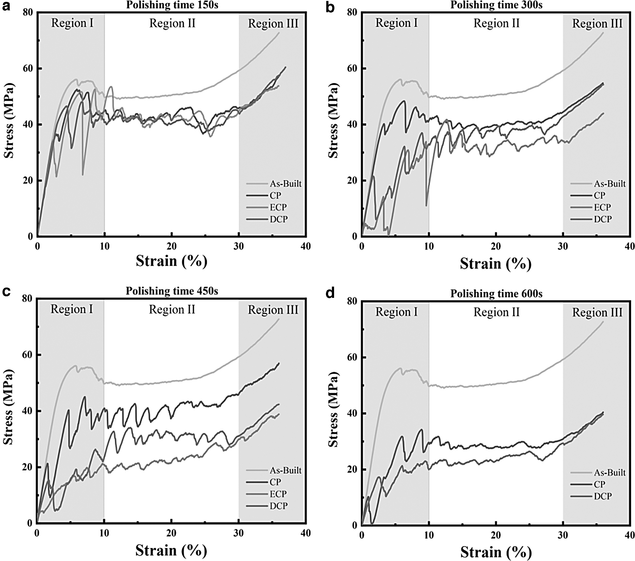
Static and dynamic axial compression mechanical tests were performed on the porous scaffold samples before and after treatment. Figure 11 shows the representative stress-strain curves of the porous scaffold samples under different treatment processes and times. The mechanical property evaluation was not completed for the samples treated for 600 s in the ECP group due to the severe damage on the outer layer structure. The stress-strain curves for each group of samples can be divided into three regions. Region I is an elastic region where the stress reaches its first peak; Region II shows an initial sharp drop in stress followed by stress fluctuation; and Region III shows a rapid stress increase due to the densification effect (Fig. 11).
Representative stress-strain curves of scaffold compression tests before and after polishing treatment.
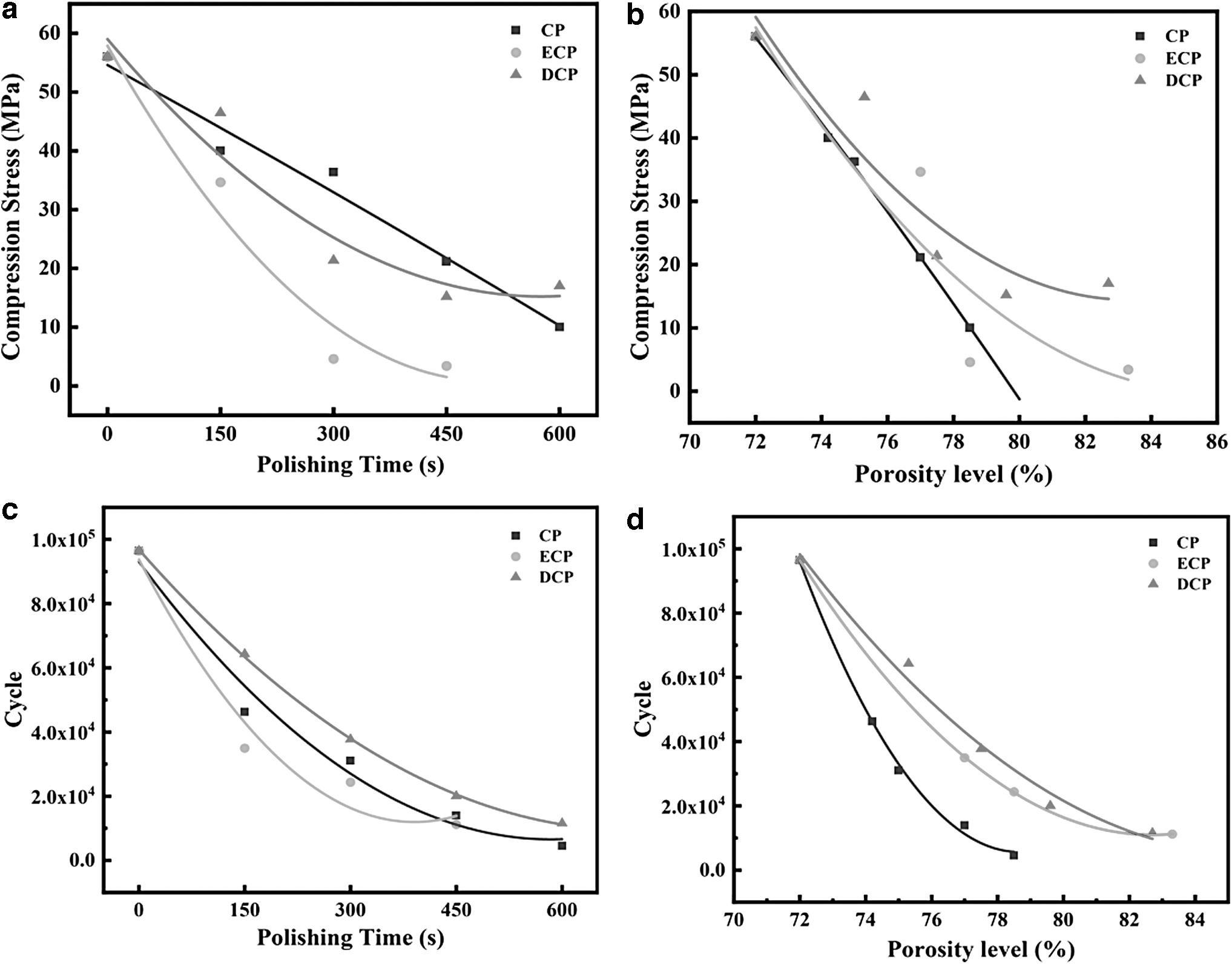
The maximum compressive strength of each group of scaffold samples before structural damage was selected based on the stress-strain curves (Fig. 11). The overall trend of compressive strength after fitting the three polishing methods under the same treatment time showed that the order is CP > DCP > ECP, while the compressive strength showed a gradually decreasing trend with increasing treatment time under the same polishing method (Fig. 12a). To further confirm the relationship between mechanical properties and scaffold morphology, porosity was plotted against the static mechanical properties (Fig. 12b). The results show that the overall order of compressive strength under the same porosity is DCP > ECP > CP.
Compressive strength of the scaffold before and after treatment and the number of cycles.
Based on the static mechanical property test, the dynamic fatigue properties of axial compression under the same force value were tested for each group of samples (Fig. 12c). The overall order of the dynamic fatigue performance of the three polishing methods under the same treatment time was DCP > CP > ECP, and the number of cycles showed an equal gradual decrease with the increase in treatment time. To further confirm the relationship between mechanical properties and scaffold morphology, porosity was plotted against dynamic fatigue performance (Fig. 12d). The results show that the overall order of dynamic fatigue performance under the same porosity is DCP > ECP > CP.
Discussion
During chemical polishing, the surface of the material pore structure is treated through the penetration of the etchant inside the porous scaffold, also employing the selective surface treatment effect achieved by the relative dose difference between the valley and peak areas of the local material surface. This technology is one of the most reliable ways to surface treat 3D printed porous scaffolds. 20 The field of implantable medical devices seeks excellence in biological performance. As a result, the pore structure of scaffolds prepared by 3D printing technology is often characterized by small unit size, pore diameter, and rod diameter, and this structural characteristic will greatly challenge the polishing of residual powder on the surface of porous scaffolds. 21
Therefore, researchers have developed an ECP technology based on the principle of anodic dissolution, which improves the efficiency of CP treatment and simultaneously optimizes the local treatment effect. This is achieved by clamping and energizing the sample in the CP process to form an oxide of uneven thickness and high resistivity on the surface of the sample, and relying on the uneven distribution of the oxide and current density in the peak and valley areas.22,23 In addition, the introduction of magnetic stirring into the dynamic chemical polishing technology has also become one of the solutions. Through magnetic stirring, the etchant is enabled to flow at a certain speed, improving the CP in the porous support of the uneven etchant distribution, and the stability and uniformity of the CP. 16
Analysis of previous literature showed notable differences in the research methods of similar works. One of the main points involves the choice of sites for the porous scaffold surface evaluation after chemical polishing treatment, which may lead to different conclusions. By analyzing the entire structure of the porous scaffold, it is easy to find that the contact between the external surface of the porous scaffold and the acid solution is more direct and sufficient. The polishing effect is more obvious in the process of treatment. Due to the complexity of the spatial environment, the internal polishing treatment effect of the porous scaffold is relatively poor. In the post-processing characterization session, if the target of analysis is determined on the outer surface of the porous scaffold, the results obtained from the analysis are not representative of the overall state of the porous scaffold. This has been confirmed in relevant studies.
On this basis, the staircase effect of SLM technology in the material preparation process can be analyzed to show that the powder particles that adhered to the upper surface of the porous scaffold basically melted due to the direct laser irradiation of its surface. While the side and lower surfaces of the porous scaffold failed to receive direct laser irradiation, many large powder particles still adhered to its surface. If the target of the analysis is the upper surface that is directly irradiated by the laser, the results of the analysis are still not representative of the entire state of the porous scaffold. Therefore, it is crucial to identify the specific area where the porous scaffold is characterized and observed during the chemical polishing of 3D printed porous scaffolds.
The above-mentioned technologies have not been comprehensively evaluated for the actual treatment effect on small-aperture 3D printed porous stents and their application in the field of implantable medical devices. The specific differences and their mechanisms are also not clear. Therefore, it is impossible to provide a process solution with guiding significance for the actual product post-treatment process through experimental studies.
To address this limitation, this study compares the effects of three processing techniques, namely pure CP, ECP, and DCP, on the surface treatment of small-aperture 3D printed porous scaffolds and their prototype structure, providing a comprehensive analysis. It is worth noting that the surface morphology of the 3D printed porous scaffold in this study was obtained by characterizing the lower surface of the upper half of the porous scaffold at 50% of the printing direction. This region represents the lower surface, where the powder adhesion of the porous scaffold is most severe.
Through the evaluation of the overall porosity of the treated sample, the results of this study are basically consistent with the characteristics of the process itself. The ECP process highly increases the processing speed of polishing, due to the enhanced ion exchange between the etchant and the sample, while the DCP process increases the local etchant concentration inside the porous support, due to the accelerated etchant flow, which also increases the etching rate.24,25
However, the evaluation of the polishing effect in the case of porous scaffolds is not only about the efficiency of the process but also about its stability and uniformity. The results of the quantitative analysis on the pore morphology in the median section show that the treatment of the porous scaffold by all three processes causes great differences in the surface treatment effect of the inner and outer structure The DCP technique can alleviate such defects to some extent, while ECP aggravates them. The specific reason for this result may be related to the consumption of hydrogen ions in the etchant caused by the chemical polishing process.
The relative lack of hydrogen ion mobility within the etchant in the porous scaffold decreases the exchange rate between hydrogen ions and metal ions, thus causing a considerable difference in the treatment effect between the inside and outside of the scaffold. 16 While ECP accelerates the loss of hydrogen ions, it does not improve the source of hydrogen ion replenishment, and instead aggravates the defect. On the other hand, DCP mitigates this defect to some extent by improving the etchant flow rate and thus replenishing the hydrogen ion consumption. 26
On the basis of this study, further analysis of the mechanical properties of each group of samples showed that their overall static and dynamic mechanical properties followed a decreasing trend, when the treatment time was gradually extended. The maximum compressive strength of samples decreased notably and was lower than the average value of the stress fluctuation stage because of the difference of the inner and outer layer treatment effect, which led to the early damage of the outer layer structure.
In addition, because the DCP mitigates the difference between the inner and outer layer treatment to some extent, the static and dynamic mechanical properties of samples treated by this process are higher than those of pure CP and ECP under the same porosity. Study of the damage forms of each sample group reveals that the inner and outer structure of the porous bracket samples treated by the dynamic polishing process are relatively uniform, which makes the stress distribution of the samples relatively uniform under axial compression, and thus gives them better mechanical properties.
In addition, the standard lines of the sample cross-sections after all chemical polishing processes showed an upward shift due to fixation of the OUT UP and OUT LOW directions of the treatment process. This implies that, in addition to the difference between the inner and outer layers, there is also a difference between the upper and lower part of the sample treatment effect, which was further verified during SEM examination of the sample cross-section. A potential explanation may be that during the chemical reaction, a large amount of gas is generated when the metal sample reacts with the etchant.
This gas generated under the porous scaffold shows a tendency to move upward in the etchant, which will evacuate the etchant solution locally in the structure above the scaffold to a certain extent, thus slowing the chemical polishing reaction of the structure above the scaffold. 27 Compared to the pure CP process, ECP has a faster reaction rate and also produces more gas, thus leading to an upward shift of its standard line. While DCP increased the lateral flow of the etchant and alleviated the issue of gas accumulation inside the porous holder, it still did not alter the general trend of upward gas movement, and the same phenomenon of severe upward deviation of the standard line was observed. 11
A potential reason for the difference in the treatment effect between the inner and outer layers is that, in addition to the complex pore structure inside the scaffold that causes the etchant to be ineffective in replenishing sufficient hydrogen ions, the gas generated during the treatment process is also an important factor affecting the difference between the inner and outer layers. In addition, the theoretical analysis revealed that the smaller the pore size of porous scaffold pore structure, the poorer the mobility between the pores inside the scaffold is, and the less conducive to the diffusion of gas to the outside world. This leads to higher gas accumulation inside the porous scaffold, resulting in poor treatment of the local scaffold surface. 17
In summary, the suggested superior treatment of the surface of the 3D printed small-aperture porous scaffold applied in the field of implantable medical devices is DCP. Nevertheless, the actual polishing process parameter settings require further adjustment according to the thickness of the porous scaffold pore structure, pore diameter, rod diameter, and other structural parameters of the corresponding chemical polishing time, etchant concentration, and flow rate. Simultaneously, future research should also focus on the further reduction of gas production during etchant treatment of metallic materials, or adopt a new processing technology and structural design to further accelerate the discharge and dissolution of gas inside the sample.
Conclusions
In this study, the surface morphology and mechanical properties of laser-selective melting Ti-6Al-4V porous scaffold samples are evaluated and analyzed with three different chemical polishing processes: simple chemical polishing, electrochemical polishing, and dynamic chemical polishing. The following findings are reported from the results:
The treatment effect in the inner and outer structure of the porous scaffold differs greatly after chemical polishing. This difference causes the early damage of the outer structure of the porous scaffold sample and the degradation of the overall mechanical properties of the sample. The restricted exchange of etchant caused by the complex internal structure of the porous scaffold and the gas generated by the chemical reaction, which is accumulated inside the material and cannot be timely eliminated, lead to this result. In the porous scaffold chemical polishing surface treatment, its internal etchant cannot be efficiently and rapidly exchanged, due to the complex internal pore structure. Therefore, the etchant treatment of the porous scaffold surface results in differences in the effect of the chemical polishing treatment between the inside and outside. Through the dynamic chemical polishing process, this can be reduced to a certain extent, so that the porous scaffold samples have better overall uniformity and mechanical properties. In the porous stent chemical polishing process of the surface, the reaction between the etchant and the metal porous material releases a large amount of gas, which will accumulate inside the porous scaffold and empty the scaffold surface local etchant. This results in the slowdown of the surface treatment of the part, further aggravating the phenomenon of nonuniformity of porous scaffold processing. Electrochemical polishing with high reaction rate characteristics will aggravate the phenomenon to a certain extent, leading to further increase in the difference between the inner and outer layers of the porous scaffold samples.
Footnotes
Authors' Contributions
W.P.: Conceptualization and writing—original draft. C.C.: Writing—original draft, methodology, and formal analysis. J.H.: Investigation and validation. Y.L.: Investigation and formal analysis. M.L.: Resources. C.S.: Supervision. W.S.: Conceptualization and writing—review and editing. All authors have read and agreed to the published version of the article.
Author Disclosure Statement
No competing financial interests exist.
Funding Information
This work is financially supported by the National Natural Science Foundation of China (No. 62073089); the Special Project for Key Fields of Higher Education in Guangdong Province (No. 2020ZDZX2061); and Special Funds for the Cultivation of Guangdong College Students' Scientific and Technological Innovation (“Climbing Program” Special Funds) (No. pdjh2023a0242). Postgraduate Education Innovation Project of Guangdong Ocean University (No. 202327).