
Abstract
Additive manufacturing (AM) of large objects has, over the last decade, required the scaling of existing material extrusion processes. The current generation of large-scale printers are primarily gantry robots with high-throughput extrusion systems. With workspaces approaching 50 m3, these printers have pushed the boundaries of achievable print volume while allowing the utilization of low-cost feedstocks, such as cementitious materials and polymer pellets, like those used in injection molding. Continued workspace expansion requires an examination of the inherent trade-offs, which impact capital and operational costs. In this work, the authors examine these trade-offs to determine fundamental scaling laws for existing system architectures, survey the state of the art for alternative system configurations, and pose recommendations for future system designers to continue the evolution of large-scale AM systems.
Introduction
Additive manufacturing (AM) began in 1983 with the invention of stereolithography by Chuck Hull. 1 For most of the history of industrial AM technologies, the workspace, throughput, and cost of these processes were limited to approximately <1 m3, 500 cc/h, and >$200/kg, respectively. 2 Recent advancements in systems have enabled low-cost feedstocks and stretched the workspace and throughput to seemingly fantastic scales. 3 The Ingersoll MasterPrint, the largest of the commercially available thermoplastic polymer material extrusion 3D printers, can print at rates greater than 70 kg/h with a cartesian (XYZ) workspace starting at 6 m × 4 m × 2 m, 4 recently setting the Guinness world record for largest 3D-printed polymer object.
While the scales of these systems have increased dramatically, the printers’ configurations are identical to their smaller counterparts, that is, gantry robots with extended X, Y, and Z axes. To date, the assumption that a system’s workspace must exceed the size of the object to be printed has not been challenged in the majority of commercial large-scale AM systems. These scaling operations incur penalties of system mass, stiffness, capital cost, and operational and installation costs such as space, power, and calibration labor. Such costs and penalties must be weighed against the machine utilization, target applications, and finishing requirements to ensure economic and technological viability. For example, using a system of extreme volumetric scale with low material throughput to produce parts that require a fraction of the useable workspace would be difficult to justify based on the $/kg of finished parts. Hybrid machines that combine AM and conventional machining processes exacerbate these penalties by increasing the required system stiffness to accommodate machining forces and achieve reasonable material removal rates.
Next-generation large format additive manufacturing (LFAM) systems will require a better understanding of the costs and benefits that are inherent to scaling AM. In pursuit of this better understanding, in this work, we attempt to uncover the fundamental scaling laws of existing gantry systems to determine characteristic equations that define the boundaries and penalties of continuing to expand the workspace of AM. For comparison, we explore alternative machine configurations, which may have the potential to reduce these pressures for some applications and continue the growth of large-scale AM. Finally, we present recommendations for future system designers to reduce the capital and operation cost and improve the utility of these unique platforms.
Methods
Why use gantries for AM?
The build volume and dynamic performance of an additive process are largely determined by the architecture of the used motion system. In LFAM, a part is printed via serial translation of a printhead along a predetermined trajectory. To maintain control over the deposition head during the process, the motion system must be designed to provide appropriate relative velocities and forces between the part and the printhead throughout the build volume. Several equations, presented below, help define the capabilities of a motion system and thus guide design.
Yoshikawa presented an analysis of a generalized motion system consisting of
An orthogonal three-axis gantry has a manipulability metric of unity across all configurations
With regard to control effort due to inertial or process loads, Paul and Stevenson describe the relationship between the required joint driving moments,
Considering an arbitrary normalized control effort
In the context of system design for LFAM, the relative masses of each orthogonal axis, including the time-varying part mass if axis-mounted, determine the dimensions of the manipulating force ellipsoid and therefore the most responsive axes. Said axes should be used for most toolpath segments during a print to optimize productivity.
Nongantry motion systems (e.g., robotic arms, SCARA arms, polar gantries, delta gantries) yield nonellipsoidal force and velocity envelopes, which show promise for hybrid, multiagent, and specialized AM systems, but introduce drawbacks such as nonconventional build envelopes and additional kinematics and path planning complexity.
Scalability of gantry systems
To assess the scalability of gantry systems, a simple model of the costs of scaling was developed using beam table deflections with the assumption that gantry cost is proportional to frame mass. Here, the mass of the different gantry elements will be estimated moving from the z-axis out to the x-axis. Figure 1a shows the z-axis of the gantry cantilevered down with the extruder on the end. The length of the z-axis is
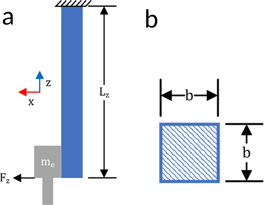
Modeling the z-axis as a cantilever beam, the deflection at the tip, as per Euler–Bernoulli beam theory, is as follows:
Cost is assumed to be proportional to mass, introducing a new constant,
The y-axis is shown in Figure 2a with the mass and the dynamic force.
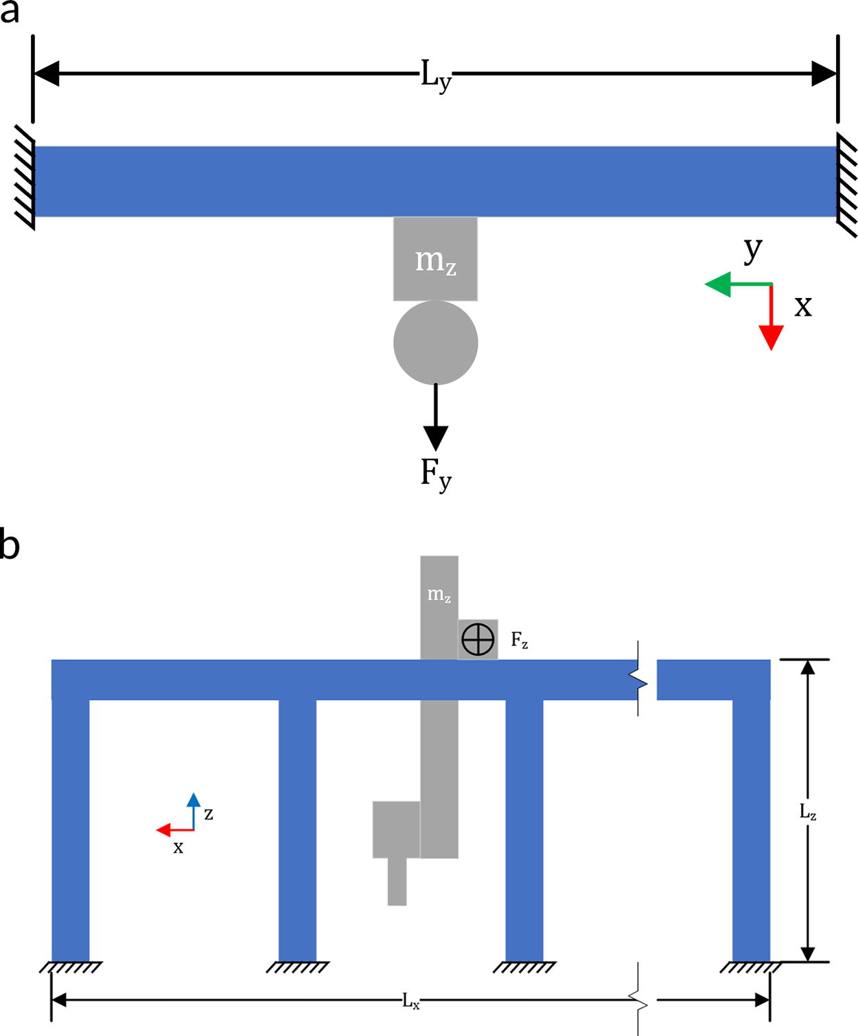
The dynamic force is
This leads to a y-axis cost of:
The x-axis, shown in Figure 2b, is slightly different. The worst-case scenario for the supports that hold the x rail occurs when the z-axis moves into or out of the page. Thus, the dynamic force (into the page) is
Solving for mass again yields the following:
The number of the supports needed is directly proportional to
This leads to the cost of the x-axis as follows:
By summing the cost of the x, y, and z-axes, the total gantry cost can be estimated as follows:
This total cost estimate is a function of the length of the three axes and the allowable deflection. It is calibrated by 3 constants. The value of the constants cannot be derived but is used to fit the model to the magnitude of costs. However, the model shows how the costs will scale, regardless of the constants used.
To probe the model, it will be assumed that
First, a scaling of independent axes will be looked at with an assumed allowable deflection of
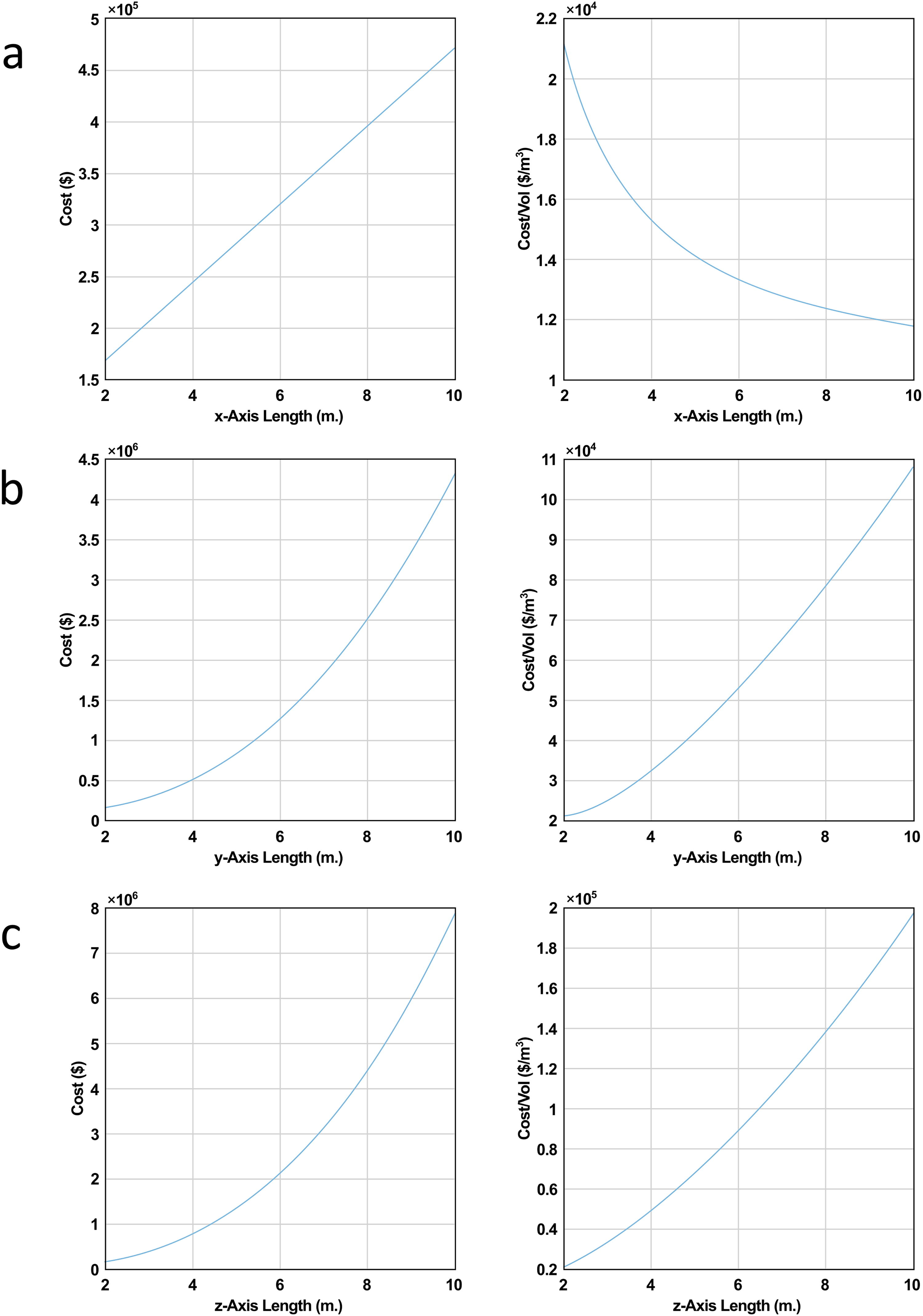
Cost for scaling by axis:
An examination of scaling the y-axis, while holding x and z constant at 2 m, is similarly shown in Figure 3b. In this case, both the cost of scaling and the cost per volume increase as a power function. Scaling the z-axis in a similar manner, while holding x and y constant at 2 m, is shown in Figure 3c. These trends also follow a power function.
The cost trends when all three axes are scaled together are shown in Figure 4a. Again, the cost increase is a power function, but in this case, the rate at which the cost per volume increases is sublinear.
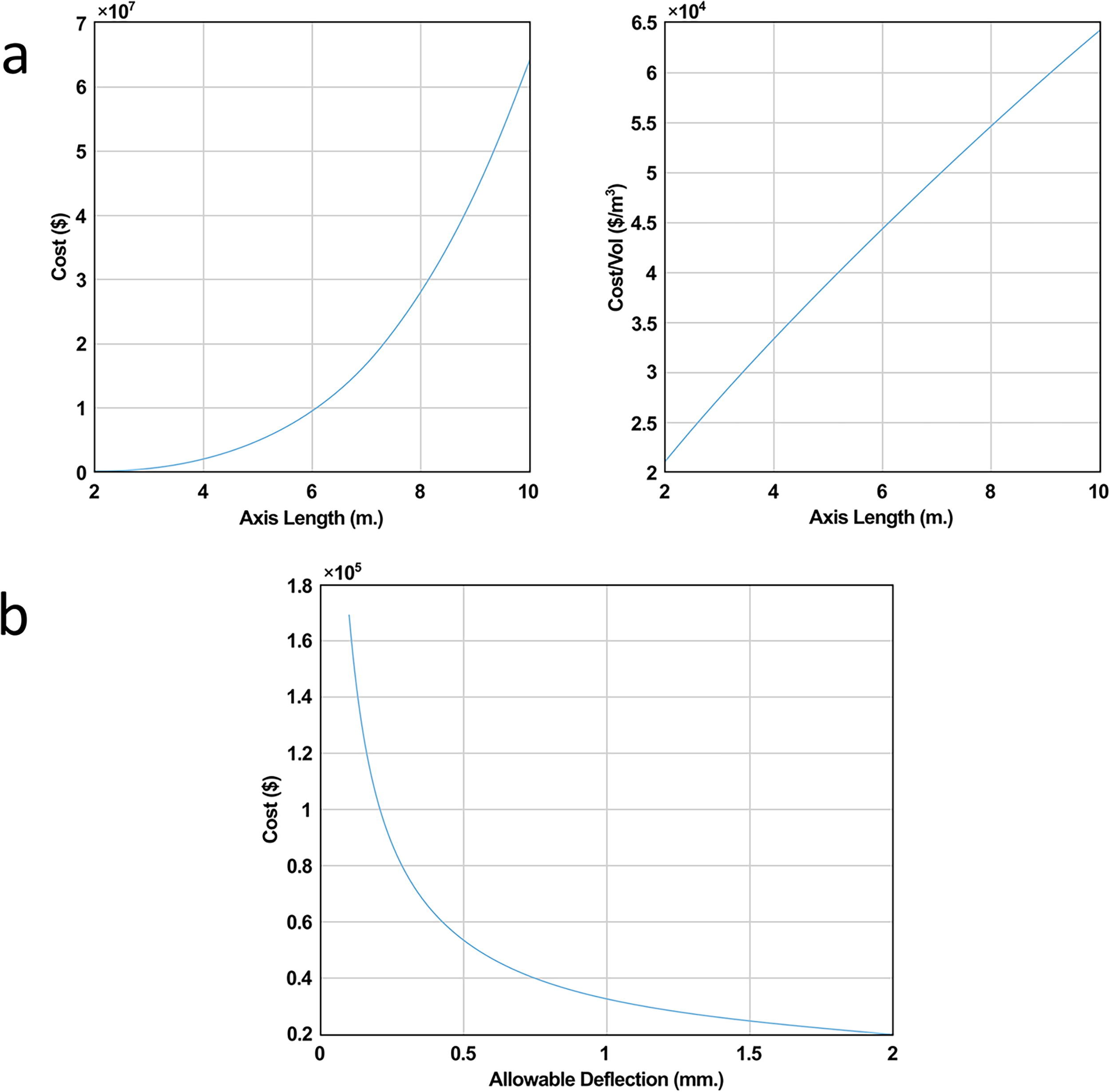
To examine the effect of increasing the allowable deflection, a system with all the axes set at 2 m is considered with increasing deflection values. The resulting cost trend is shown in Figure 4b; increasing the deflection causes a significant decrease in system cost, following an inverse root-type curve.
From this model, it is apparent that scaling up increases the cost per volume, except for the case of scaling the x-axis alone. In this model, the mass of the extruder is assumed to be constant during scaling and is abstracted away in a constant term. However, when scaling the dimensions of a system, it is also common to scale to a larger extruder to enable higher deposition rate in the larger volume. If the increase in extruder mass was accounted for, the cost of scaling would be even more significant. With the increase in cost per volume for most cases of scaling, there is clearly a scaling limit for gantries, although where this limit lies will be application dependent. Scaling in the x direction alone can be advantageous in terms of cost per volume. Unfortunately, to increase machine capability, it is usually necessary to scale all axes, with z-axis scaling being often the most valuable to increase capability.
In contrast, relaxing the requirements on deflection significantly reduces the cost of machines. This can be used as a factor to combat the cost limitation of scaling. However, advanced control techniques may be necessary to accommodate increased deflection.
Alternative Methods
Several variations and alternatives to gantry systems exist for AM systems, such as track-mounted, 45-degree belt gantry, freeform following, multiagent, and cable driven. Each configuration has its merits, which are outlined in the following subsections.
Track-Mounted printers
One way to minimize the effects of gantry scaling issues is to only increase build volume in one dimension. The chosen dimension would likely be the one that is least affected by the scaling factors: X. There are many ways this can happen, but most examples involve mounting a robotic arm along a track system. In that application, the length of the part can be as long as the track, but the other two dimensions would still be limited by the reach of the robot.
Track-mounted printers are ideally suited to long straight parts with a relatively narrow cross-section. This setup also allows for consecutive production of parts. The main issue with this approach is that it does not entirely avoid the scaling cost issues that were presented earlier; it simply minimizes the effects of those issues. In addition to cost scaling, this method requires permanent equipment installation, which leads to further capital expense.
45-Degree belt printers
Another way to increase the build volume in one dimension is the belt printing approach, which uses a belt conveyor in place of a fixed print bed. With this method, the build volume can be considered infinite in the direction of the conveyor, whereas the other two directions are limited by the size of the gantry. However, printing an extremely long part would result in layer times that were too long to be viable, because the printhead would have to travel the whole perimeter of the part for each layer. To avoid the excessively long layer times, the printhead and gantry are located at a 45-degree angle relative to the conveyor belt, hence the name “45-degree belt.” Shifting the layer profile away from the infinite build direction reduces the perimeter of each layer to a 45-degree cross-section of the part, instead of the entire perimeter of the part.
This type of arrangement is commercially available from several manufacturers. The primary advantage of this arrangement is the ability to produce very long, continuous parts in a single dimension, at a minimal cost. An additional benefit is that this arrangement can be used for continuous part production without user intervention.
The primary disadvantage of this method is that the build volume is still limited in two directions, by the size of the gantry. 8 This means that applications would be limited to long parts with a relatively small cross-section. To scale up in the other two dimensions, the gantry scaling factors previously discussed would apply. In the case of a long continuous part that exceeds the length of the conveyor bed, there is a need for additional rollers to support the part as it moves off of the conveyor belt. The support rollers could result in additional capital expenses, as well as occupying valuable floor space in a production environment. For extremely long parts, it is likely that the weight of the parts and resulting drag from the rollers would exceed the ability of the conveyor to advance the part. In this case, additional hardware might be needed to assist or replace the conveyor in moving the part. While it can be considered infinite in theory, there are practical limitations that will limit the length of the parts that can be produced. Figure 5 shows a 45-degree belt printer.
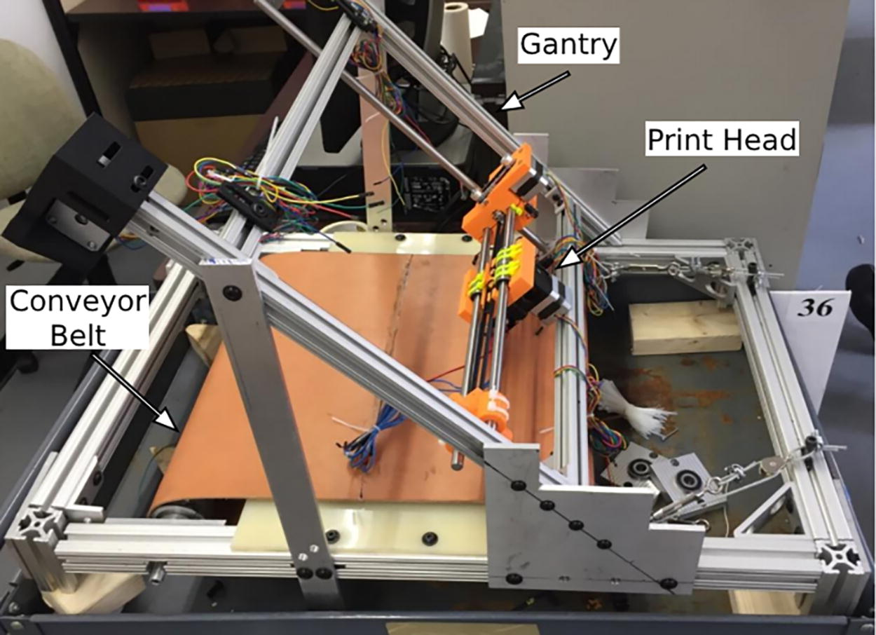
A 45-degree printer. 8
Freeform following printer
A freeform printer is one that does not provide any limitations on size or shape of the printed object. One idea for a true freeform printer was demonstrated by MX3D, using a robot-driven arc-welding printhead. 9 The freeform nature of this concept is based on the robot being moved successively, throughout the print, by mounting it to the previously printed structures. The advantage of this configuration is the unrestricted and infinite build volume in all three directions. In the demonstrated application using arc welding, there were no requirements for support material.
However, there are several disadvantages to this type of configuration. One disadvantage is that this type of configuration is not possible for certain lightweight geometries because the part itself must support the weight of the robot. This could be overcome by overdesigning the part or by adding additional supports. On the feasibility and production side, the main disadvantage is that the utilities and feedstock required for printing would either require complex delivery systems or else be manually moved throughout the build. In addition, the imprecise nature of arc-welding AM does not allow printed features to be used for determining the new position of the robot after it is moved. This means that an expensive laser tracker and on-the-fly path planning would need to be used to ensure that excessive errors are not accumulated throughout a print.
Multiagent printing
Multiagent robotic systems provide another freeform printing technique that can improve the throughput of manufacturing and construction systems using multiple deposition robots. This concept allows for straightforward scalability of print volume and area, with the productivity increasing with every addition of a deposition robot. While multiple agents working together can allow for a large structure to be quickly constructed, the print resolution and minimum feature size can still be maintained with this configuration because the resolution is determined by each individual agent rather than the entire system.
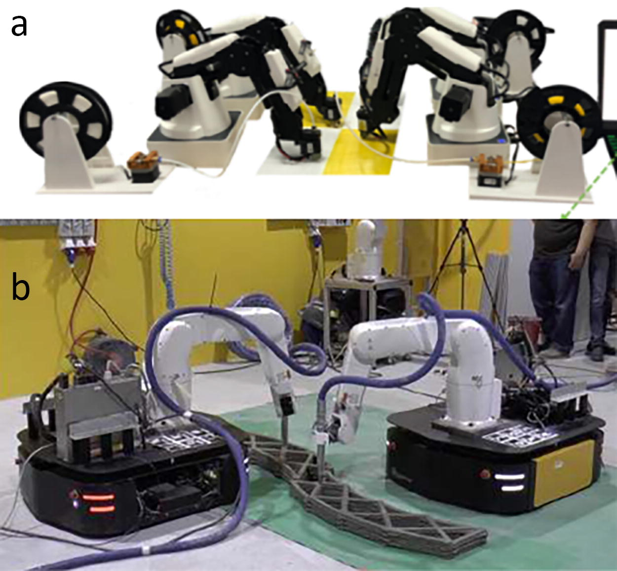
There have been several examples developed where stationary robots, each with a deposition head, have worked collaboratively to print large-scale objects. Shen et al. demonstrated this concept using four smaller robotic systems using polymer extruders to collaboratively print objects much larger than the workspace of a single robot, as shown in Figure 6a. 10 However, they pointed out the need to develop pathing and segmentation routines that can optimize the utilization of the robots. In addition, Oak Ridge National Laboratory has demonstrated a multirobot wire arc AM platform that utilizes three stationary robotic arms with a rotary table, which enables all three robots to work on the entire workpiece. 11
Clearly, the multiagent configuration allows for significantly higher system throughput. However, it requires the development of complex coordination control algorithms and pathing. Without complete optimization of path planning and segmentation of routines, the scalability of the print volume is not as straightforward as it seems.
Manufacturing using multiple autonomous robotic platforms has also been pursued. This allows for a significantly larger workspace, limited only by the limits of the travel distance of the robotic platforms. These systems enable an AM platform to produce a part that is larger than the system itself. In addition, the throughput of these systems can be scaled by adding additional deposition robots, but again, as the number of robots increases, the complexity of the control system also grows.
Zhang et al. built two mobile platforms with robotic arms mounted on them that collaboratively built parts by extruding a mortar mix, as shown in Figure 6b. 12 They noted challenges with regard to controlling such a complex system and that a significant amount of additional work is required to optimize the productivity. They also discussed problems found with the bonding between sections fabricated by different robots. Sustarevas et al. demonstrated a similar mechanical arrangement and discussed the challenges associated with locating the multiple robots relative to each other, to minimize offsets in the final built part. 13
Swarms of flying robots are currently being intensely studied for a multitude of applications such as entertainment, security, logistics, and communication. 14 There has also been research in its use in AM. Flying systems would have higher travel speeds, ignore terrain, and eliminate the limitation on Z height that exists with ground-based mobile platforms. However, these systems also have a lower payload capacity, shorter battery life, and more complex controls.
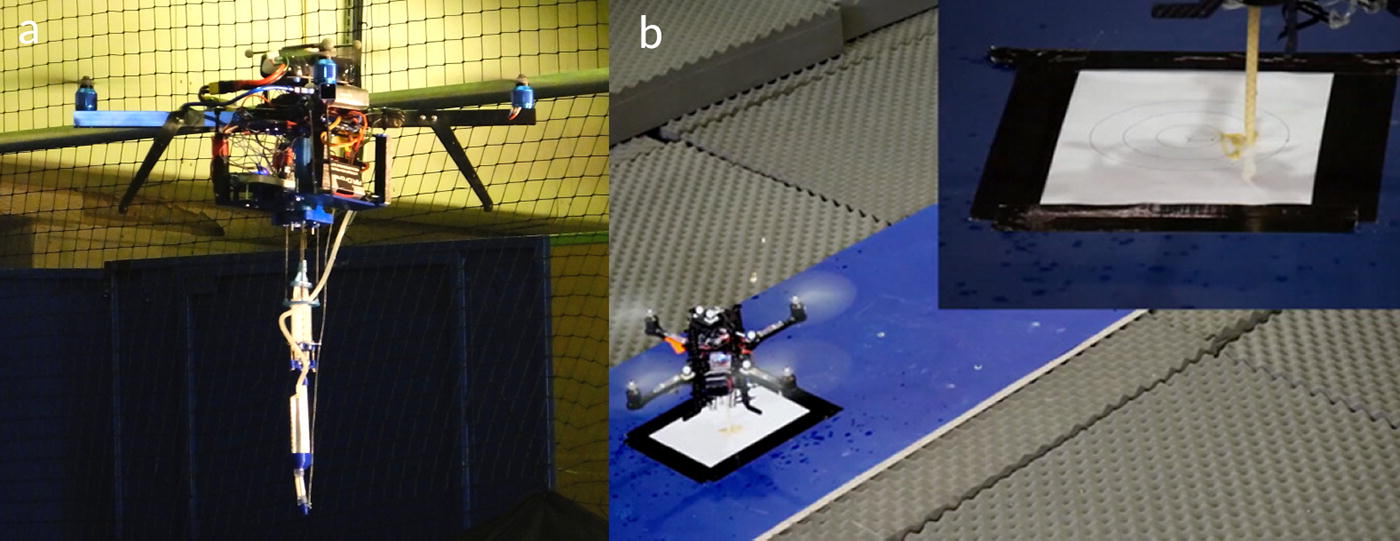
Hunt et al. showed an early concept of attaching an expanding foam injection system onto a quadcopter, as shown in Figure 7a, and showed that deposition using an arial system was possible. 15 They found that absolute positioning of the robot in space for accurate deposition placement was a significant challenge and that significant work remained to develop a corporate system. Dames et al. further developed the foaming materials and extrusion system, but the issues with positional accuracy remained, with the robot only able to place the foam within a 10 cm radius, as shown in Figure 7b. 16
Multiagent printing allows for significantly higher deposition rates and larger build volumes without the need to build enormous robotic systems. However, the controls and overall system complexity increase significantly as additional agents are added. Work on how to optimize collaboration and multirobot calibration needs to be done before wide-scale adoption of this technology will be possible.
Cable-driven printers
Cable-driven robotic systems have high payload-to-weight ratios and enable large workspaces compared with other robotic systems. 17 The FAST telescope in China demonstrates the large workspaces possible when using cable-driven robotics. 18 The telescope is shown in Figure 8a.
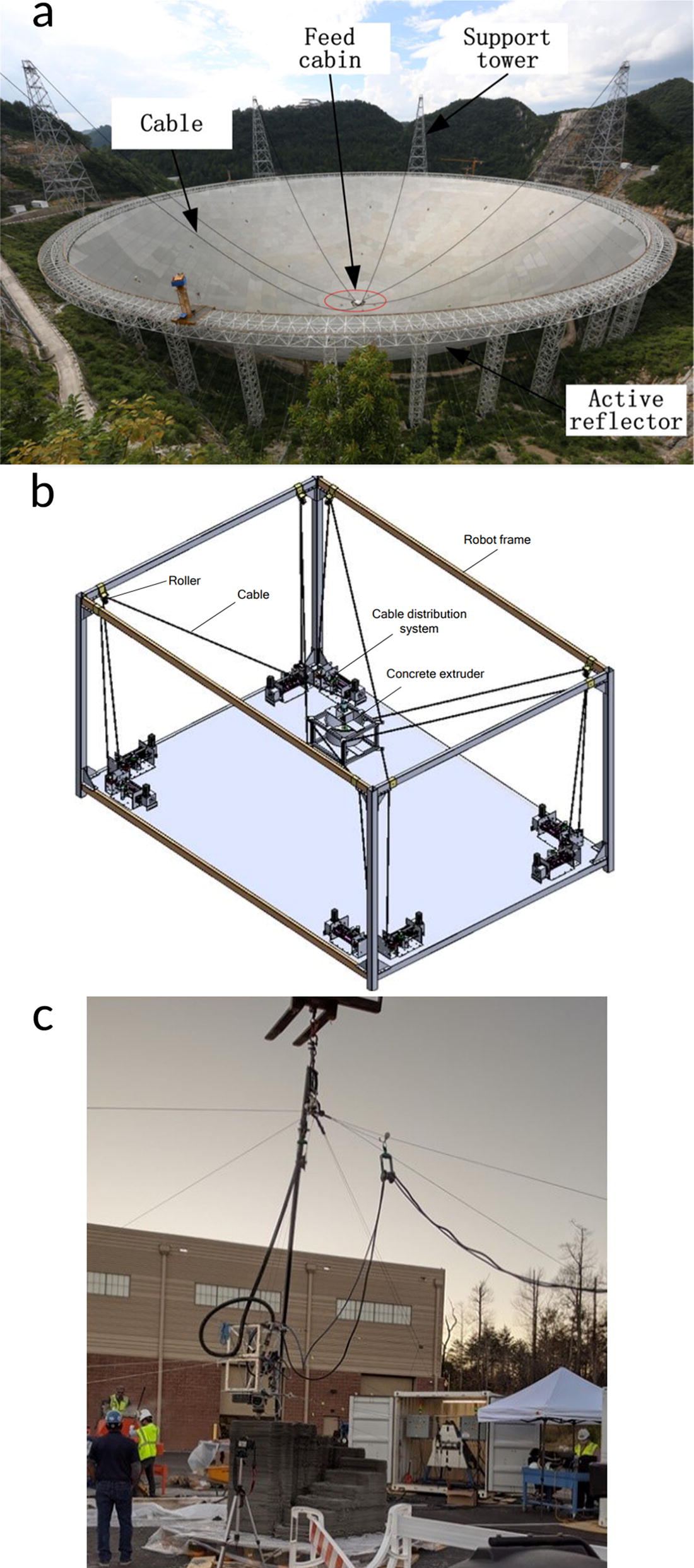
A cable-suspended system relies on gravity to provide tension on the cables. Within AM, one of the first examples of a cable-driven robot is the Hangprinter, which has printed an object that is 4.5 m in height. Barnet et al. developed a cable-suspended printer that extrudes an expanding foam. They found that shifts in the center of gravity of their end effector, due to the movement of the supply hoses and cables, would affect the accuracy of their printer. 21 Tho and Thinh have developed a cable-suspended concrete printer and developed the necessary control algorithms. A rendering of their system is shown in Figure 8b. Tho and Thinh noted the low weight and ease of assembly. However, work needs to be done in optimizing workspace and the design of this system. 19 Chesser et al. have developed concrete printers that use fully constrained cable-driven systems that have tensioning cables to increase the positional accuracy and system dynamics of the cable-driven robotic system. 20 This cable-driven system is shown in operation in Figure 8c.
Cable-driven robots have been demonstrated to enable large-scale AM platforms without the need for extremely large structural members, which reduces the overall cost and complexity of manufacturing such systems. They have also demonstrated a high degree of accuracy and controllability. Current iterations of the cable-driven systems have limitations on their workspace, but these could potentially be addressed through variations in the design. In addition, these systems have difficulty working in tandem, so scalability to extremely high throughputs will be a challenge.
Conclusions
While this article has shown that gantry systems have limited potential to scale in a cost-effective manner, there is still a need for future large-format systems that can be cost-effectively scaled up. Other alternative systems exist, but they all have their advantages and disadvantages.
When looking to the future of large format systems, a few ideas need to be kept in mind, such as the cost of the machine footprint and the stiffness requirements for additive and subtractive processes. When scaling to a larger size, it would be beneficial for the system to not permanently occupy floor space equal to the build volume. A small footprint helps to save on operational costs such as utilities, but more importantly, the cost of owning or leasing manufacturing space continues to rise year after year.
In addition, at this point, the separation of subtractive and additive processes to different pieces of equipment is recommended. AM has drastically lower stiffness requirements than subtractive. The stiffness required for subtractive processes has a detrimental effect on the overall cost of the system, because it requires a stiffer structure, necessitating a higher system mass. This additional mass also creates an increased floor load, ultimately requiring a more expensive substructure to support the overall weight of the system. AM still requires high accuracy and repeatability for consistently making high-quality parts, but these requirements can be satisfied, even with low stiffness, using input shaping and control algorithms to effectively control the system and reduce vibration.22–24
Footnotes
Authors’ Contributions
A.R.: Writing lead, formatting, and document submission. B.K.P.: Writing and project lead. P.W.: Writing, reference management, and data collection. P.C.: Data collection, equation development, and testing. A.K.B.: Writing, editing, and figure creation. A.S.: Writing, equation development, and testing. J.H.: Writing and equation development. V.K.: Project sponsor, funding, and review. J.V.: Writing, equation development, and testing. C.A.: Writing and equation development. A.J.: Writing, editing, and math solutions. M.B.: Writing and software development.
Author Disclosure Statement
No competing financial interests exist.
Funding Information
This article has been authored by UT-Battelle, LLC, under contract ![]() ).
).