




Abstract
The utilization of bone scaffold implants represents a promising approach for repairing substantial bone defects. In recent years, various traditional scaffold structures have been developed and, with advances in materials biology and computer technology, novel scaffold designs are now being evaluated. This study investigated the effects of a novel scaffold unit cell design (Hexanoid) through a computational framework, comparing its performance to that of four well-known scaffold designs. A finite element analysis numerical simulation and mechanical testing were conducted to analyze the dynamic bone ingrowth process and the mechanical strength of the different scaffold designs. Bone formation within the Ti-6Al-4V metal scaffolds was simulated based on the theory of bone remodeling. The outcomes of the study reveal that the novel scaffold design (Hexanoid) attains a notably elevated ultimate bone volume fraction (∼27%), it outperformed conventional unit-cell designs found in extant literature, such as cubic design with 19.1% and circular design with 16.9% in relation to the bone-to-cavity volume ratio. This novel structure also has comparable mechanical strength to that of human compact bone tissue. While the design was not optimal in every category, it provided a very satisfactory overall performance regarding certain key aspects of bone performances in comparison with the five scaffold structures evaluated. Although limitations exist in this project, similar methodologies can also be applied in the primary evaluation of new scaffold structures, resulting in improved efficiency and effectiveness. In future research, the results of this project may be integrated with clinical rehabilitation processes to offer a critical evaluation for optimization of additional novel scaffold unit-cell structure designs.
Introduction
Scaffolds may be required to facilitate reconstruction of bone defects when their size surpasses a threshold beyond which the body cannot fully heal itself through natural means. This is because in cases where the defect area has a gap of 30 mm or greater, the human body generally cannot heal spontaneously and requires external surgical intervention to restore skeletal continuity and allow individuals to regain normal mobility. 1 The 3D-printed bone scaffolds have been extensively researched, with varying materials and architecture designs being studied.2–4 Human bone ingrowth within implanted scaffolds, alongside their mechanical properties and porosity, are critical factors to consider in the clinical context. The bone growth rate and final occupancy proportion significantly influence scaffold incorporation and the likelihood of implant failure. 5 Consequently, repeated in vitro and in vivo experiments and research are required to optimize scaffold design and improve their performance. However, evaluating the impact of each specific scaffold parameter on tissue regeneration using these techniques is costly and time-consuming.
To reduce the cost and time associated with these evaluations, finite element analysis (FEA) numerical simulations can be performed to provide a reference or guide being before conducting in vitro experiments or in vivo implantations.
FEA of bone remodeling is a cost-effective method for investigating the mechanical and biological behavior of patient-specific implants. FEA involves dividing the continuous solution area into smaller elements, which are connected in a specific manner. Since the elements can be combined in different connection modes, and the elements themselves can have different shapes, it is possible to model the solution domain for very complex geometric shapes. The finite element method also involves the use of approximate functions within each element, with the solution of each element being combined to solve the entire solution domain. The approximate solution is expected to converge to the exact solution, assuming the elements meet the convergence requirements. 6
There are several potential candidate materials for bone scaffolds, such as plastic polymers, ceramics, and alloys, all of which need to fulfill certain criteria. First, they should possess high cell or tissue biocompatibility to avoid immune reactions and associated clinical complications, including local necrosis. 7 Additionally, the scaffold needs to exhibit sufficient strength to withstand local stresses, and its overall Young's modulus should be similar to that of cortical bone to prevent stress shielding. 4 With the advancement of personalized medicine, it is preferable for bone scaffolds to be 3D-printable to correspond to the patient's specific lesion, thus achieving better surgical integration and recovery outcomes. In this study, Ti-6Al-4V was chosen as the material for the bone scaffold. As a widely used titanium alloy in clinical settings, this material meets the aforementioned criteria.8,9 Furthermore, by means of refined laser powder bed fusion manufacturing technique, the Ti-6Al-4V alloy can attain noteworthy attributes, including high compressive yield strength, near trabecular bone elastic modulus, deliberate formation of porosity, and optimal surface roughness.10,11
These characteristics render it particularly advantageous, especially in the context of unbiodegradable implant materials. In addition to the selection of scaffold material, there are some central rules and key constraints in scaffold unit cell design. Basically, the tissue-specific design of the scaffold is supposed to stimulate and directs tissue regeneration, guiding the initial host response and facilitating the formation of functional tissue by providing a surface and void volume that promote connective tissue growth. 12 The pore shape, size orientation, and continuity ought to be designed in balance for better osteoinductivity. 13 Unreasonable substructure sharp corner or thin beam can induce unbalanced stress distribution within scaffold surface and cavity. 14
Similar simulations of bone ingrowth have been conducted using different scaffold structures and based on various remodeling theories. In 2004, a computer aided design-based microsphere-packed bone structure was developed by Lal and Sun, demonstrating the feasibility of bone ingrowth simulation studies. 15 Subsequently, the relationship between the mechanical effects and bone formation in scaffolds made of various materials has been investigated extensively.16,17 Dynamic mechanical stimulation with higher stresses has been found to generally promote bone tissue formation, while local flow velocity and local shear stress have been shown not to significantly impact tissue remodeling.18,19 In the context of in vivo experimentation, tissue proliferation within 3D printed Ti-6Al-4V bone scaffolds implanted in the distal femoral region of rabbits has been subjected to evaluation by Deng et al. 20
The scaffold configurations employed in the aforementioned studies for bone remodeling simulations have exhibited a degree level of simplicity in their design. Certain inherent structural characteristics of conventional scaffolds, characterized by sharp corners and edges, can give rise to nonuniform distributions of strain energy density (SED). Consequently, the desirable ultimate bone-to-cavity ratio becomes compromised. Additional challenges include incongruities in the global mechanical integrity when compared with the compact bone. It may lead to stress shielding, which potentially results in the diminishment of surrounding bone tissue due to physiological loading reduction on bone structure. Some recent innovations in scaffold design have yet to be evaluated through FEA simulations of bone ingrowth. This study employs a novel structure design referred to as the Hexanoid scaffold, made from the titanium alloy Ti-6Al-4V. Mechanical properties were tested by both real compression tests and digital software simulation.
The hypothesis was that the Hexanoid scaffold would exhibit greater bone ingrowth compared with other scaffold designs, while retaining suitable mechanical properties. It is raised based on unique geometry of the Hexanoid scaffold which incorporating a periodic curved surface and alternative minimal surface.
The objective of this study was to use FEA simulation to compare the mechanical strength of five scaffold unit cell designs and the potentials for mechanical loading to stimulate bone ingrowth into these scaffolds, including conventional and novel designs. The goal was to determine which design was the most suitable for use as a bone scaffold implant based on the results of the comparison.
Methods and Designs
Bone ingrowth simulation
Computer simulation was used to examine bone growth during the remodeling phase, which was numerically implemented by coding the subroutine VUMAT of the commercial finite element software Abaqus (Dassault Systèmes, USA), which also has been chosen for bone growth FEA evaluation in several previous studies. 21
Material and scaffold structure design
The choice of the scaffold material is a crucial aspect in the design of a bone implant. Although biodegradable scaffolds have been shown to stimulate tissue growth and elicit minimal immune response after they dissolve, permanent biocompatible metals remain the most used materials due to their inherent mechanical strength, ease of large-scale manufacturing, and relatively lower cost. For this study, Ti-6Al-4V was selected as the scaffold material for all architectural designs. This material exhibits a Young's modulus of 107 GPa, a Poisson's ratio of 0.3, and a density of 4500 kg/m3. In the model the scaffold pores are initially filled with interstitial fluid (ISF) that are then partially replaced by bone tissue over time. The materials in the model, including the scaffold, bone, and ISF, were assumed to be isotropic and linearly elastic. Additionally, the ISF was assumed to be nearly incompressible.
The bone scaffold model was designed in Solidworks® and imported into Abaqus for further simulation. Each scaffold unit cell is a cube that is 1 mm on each side. There were four traditional bone scaffold designs evaluated in this study. The most common and relatively simple conventional scaffold structure are the cubic and spherical designs, which is shown in Figure 1a. We evaluated the effect of vascular growth factor and mechanical energy on bone growth through a comprehensive simulation of the cubic biodegradable scaffold in another project. 22 The spherical design is shown in Figure 1b. Figure 1c indicates the face-diagonal cube (FD-cube) unit cell, and Figure 1d illustrates the Void Octet (V-Octet) design, those two beam-based lattice Octahedron family scaffold structures were designed by Egan. 23 The novel-designed scaffold structure Hexanoid is manifested in Figure 1e. Each scaffold characteristics were evaluated associated with simulation results in the Discussion section.

The 3D scaffold unit cell module of the
Meshing and voxelization
The computational domain was Hex meshed into identical cubic elements with a side length of 50 μm. The titanium scaffold and the porous cavity were allocated as two separate sets. Both sets were converted from the continuous domain into a discrete grid block through outsourced voxelization scripts. It enables discretization of a geometry and its surrounding space into ordered and mathematically simple objects—cuboids. Originally introduced by Kaufman and Shimony. 24 The voxelization was based on each scaffold's unique structure, as indicated in Figure 1f–j. Each element (voxel) is associated with a local mineral density. If the density is less than a threshold, the element is assumed to be ISF. If the density is greater than the threshold, the element is assumed to be bone. The mechanical properties associated with that element, such as Young's modulus, depend both on whether the element is ISF or bone, and on the mineral density. To display the states during the whole process, we defined a characteristic function χ: If χ = 1, the element was in the state of the scaffold; if χ = 2, the element was in the state of bone; and the element was in the state of ISF when χ = 3.
Boundary conditions
The simulation conditions were designed to imitate the loads that would be applied to a scaffold implant in a clinical scenario. The top surface of the scaffold model was subjected to a uniformly distributed pressure, simulating the loads on the model. To ensure homogeneous deformation of the entire model in the z-direction, the bottom surface of the scaffold was fixed and a rigid plate was attached to the top surface. Consistent with Shefelbine et al. (2005), the compressive stress applied to the surface of the rigid upper plate was 3 MPa. 25 The applied pressure was defined as a trapezoidal pulse with a period of 1 day (Fig. 2), including relaxation, rising, hold, and fall phases. The latter three phases define the duration of movement, with the relaxation phase denoting idleness. The rising and falling phases of the loading history were set to 0.05 days to avoid sudden changes in the loading history, which could lead to erroneous simulations. The simulation was executed over a duration of 100 days to examine bone growth during the rehabilitation phase, as this is equivalent to the average recovery time of an individual following a fracture (∼16 weeks). 26
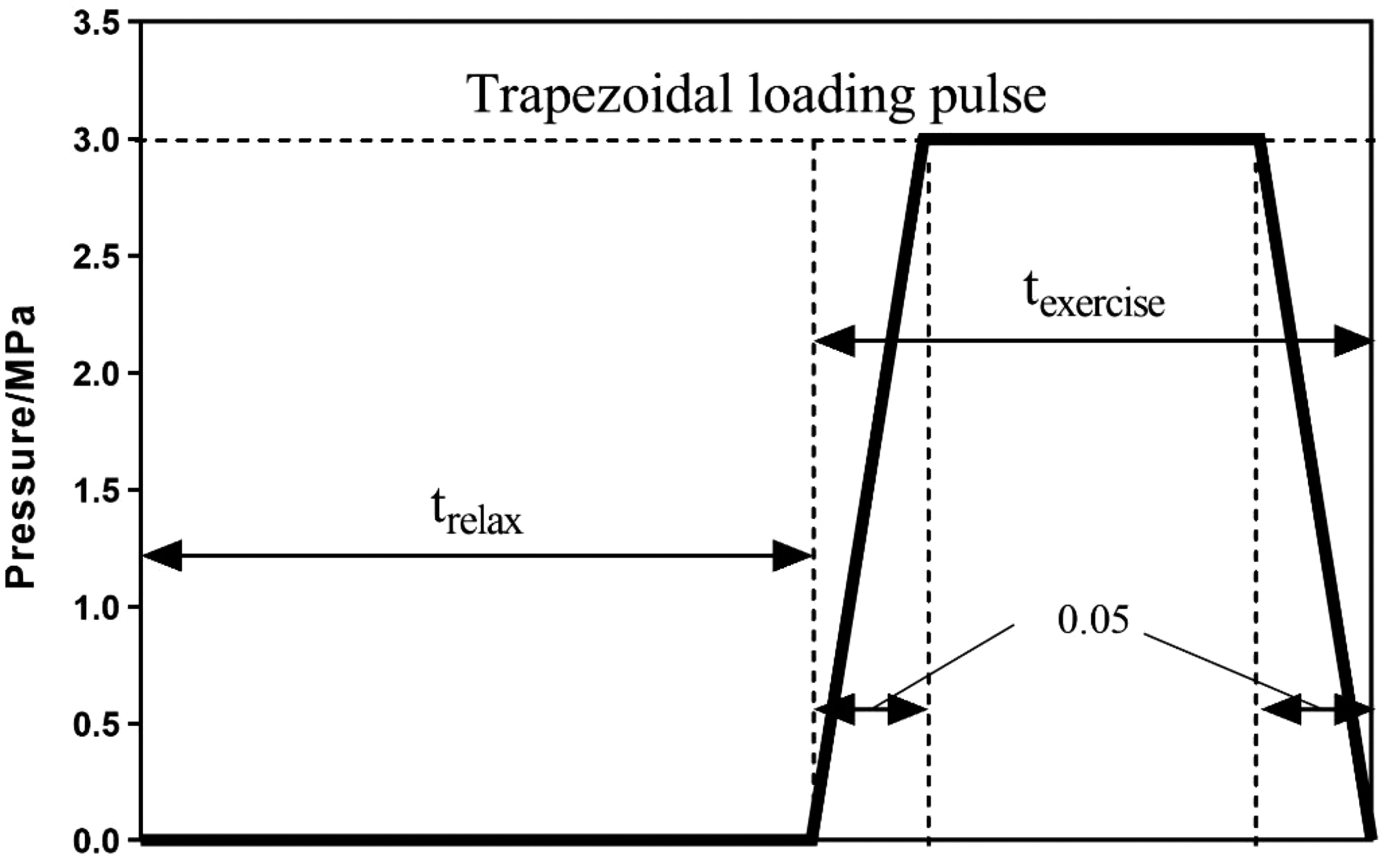
The graph of the boundary condition as the external mechanical stimulus, with time on the x-axis and pressure (in MPa) on the y-axis.
Bone remodeling theory and input parameters
The simulation of bone growth and remodeling within the scaffold is based on that proposed in Wang et al. 22 We summarize here the main elements of this computer model and refer the reader to Wang et al. 22 for more details. Bone formation and resorption is assumed to be operated by osteoblasts and osteoclasts, respectively. The osteogenesis theory posits that these cells can only respond to mechanical signals when they are attached to a scaffold or on the surface of previously formed bone that has undergone differentiation from cartilage. 27 As a result, we assume that bone resorption and formation can only occur within voxel elements adjacent to a scaffold voxel, or to a bone voxel—we do not assume that resorption and formation occurs further away within the ISF. To simplify the process, the simulation relied on the locally heterogeneous SED ψ as the sole stimulus affecting osteogenesis and resorption factors. Based on Huiskes' theory and Schulte's work28,29 the bone remodeling rate u(ψ) represents the thickness change of formed/absorbed bone per unit time, as illustrated in Figure 3, and is expressed as:
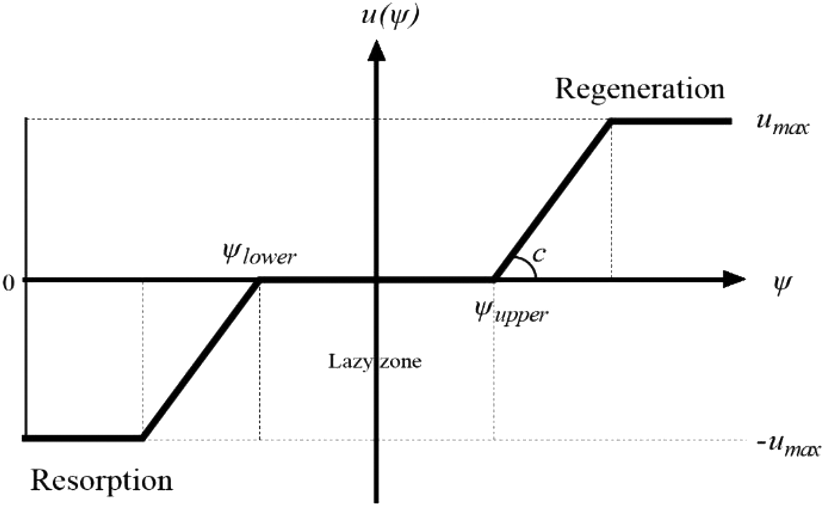
The indication of the basic principle of the bone remodeling theory, where the x-axis is the stress energy density, and y-axis is the bone remodeling rate.
In the formula, c is a constant and represents how fast bone formation and resorption rates reach the maximum growth rate umax, and ψupper and ψlower are bone formation and resorption thresholds, respectively. The “lazy zone” represents the specific mechanical stress interval in which osteoblastic and osteoclastic cellular activities reach dynamic balance. Within this interval, there is no bone formation or degeneration macroscopically. For each voxel element n, its local SED ψ (xn) is affected by its neighboring element m within a sensitive distance D. Within this range, closer element mth has a greater influence on element nth, and vice versa. The formulas of local SED can be formulated as: 29

where q is the number of other elements that has influences to this element. SED (xm) is the SED of the mth element, and d (xm−xn) is the distance between element n and m. This local averaging of SED is useful to prevent checkerboard patterns from occurring.30,31 The rate of change of bone volume (BV) fraction αb(t) of a bone element [equal to relative density
where l is the side length of the elements. The Young's modulus of the bone element at time t, Eb(t), was computed by a modified modulus–density relationship, where Eb and EISF are the Young's moduli of the natural bone and ISF, respectively.
Each element being ossified in a certain degree of bone maturation can contribute to the mechanical properties of the scaffold–bone system only when the relative density
In this instance, titanium made up the scaffold; its mechanical characteristics are already mentioned in Meshing and Voxelization section. Frost determined that the maximum rate of bone resorption or production during bone remodeling was 2 mm3/mm2/year, which translated into umax = 0.005 mm/day in the current simulations. 32 The lower and upper criteria (ψlower and ψupper) were modified based on the prior literature. 29 As indicated in Bone Ingrowth Simulation section, the boundary conditions for the rehabilitative exercise level were 3 MPa. Table 1 contains a list of all input parameters utilized in the simulation, which are same as the values used in Wang et al. simulation. 22
Summary of the Bone Remodeling Theory Parameters Used in the Finite Element Analysis Simulation
ISF, interstitial fluid.
Scaffold mechanical compression test and simulation
The mechanical strength of the Hexanoid scaffold was evaluated through a combination of experimental quasi-static compression testing and numerical simulation using FEA software. The architecture and cross-section of the Hexanoid scaffold used in the mechanical compression tests are depicted in Figure 3a. The experimental mechanical compression test was conducted three times using 3D-printed specimens composed of a 4 × 4 × 6 unit cell structure, made of Ti-6Al-4V alloy (as depicted in Fig. 3b). Similarly, the module used in the FEA simulation was designed as a 4 × 4 × 6 unit cell structure to match with mechanical testing, as shown in Figure 3c. 33 The actual size of 3D printed mechanical testing specimen (Gauge Length was ∼14 mm) was different from the simulation module, because of 3D printer accuracy and technical issues. Regarding the boundary condition, the lower surface of the compression cylinder was constrained in all direction, and a displacement of 0.3 mm (5% of strain) was applied to the upper cylinder surface.
The corresponding reaction force to the displacement was recorded as output. A stress versus strain curve was plotted considering the loaded surface area, and Young's modulus of the elastic region was calculated. The same simulation process and principle were applied in all of the other four scaffold designs to compare their mechanical strength (Fig. 4).

Results
BV versus cavity volume
The results of the osteogenesis within the scaffold cavity are presented in Figure 5. The BV to CV ratio increased dramatically during the 1st week for all scaffold designs, indicating rapid bone ingrowth. The maximum bone ingrowth was observed in the simple cube scaffold, FD-cube, and Circle scaffold unit cells around day 2. However, after the initial tissue remodeling, limited progress was observed until the end of the stimulation. The Hexanoid and V-Octet designs demonstrated significantly higher bone ingrowth and achieved steady optimum BV/CV ratios of ∼27% and 35%, respectively.
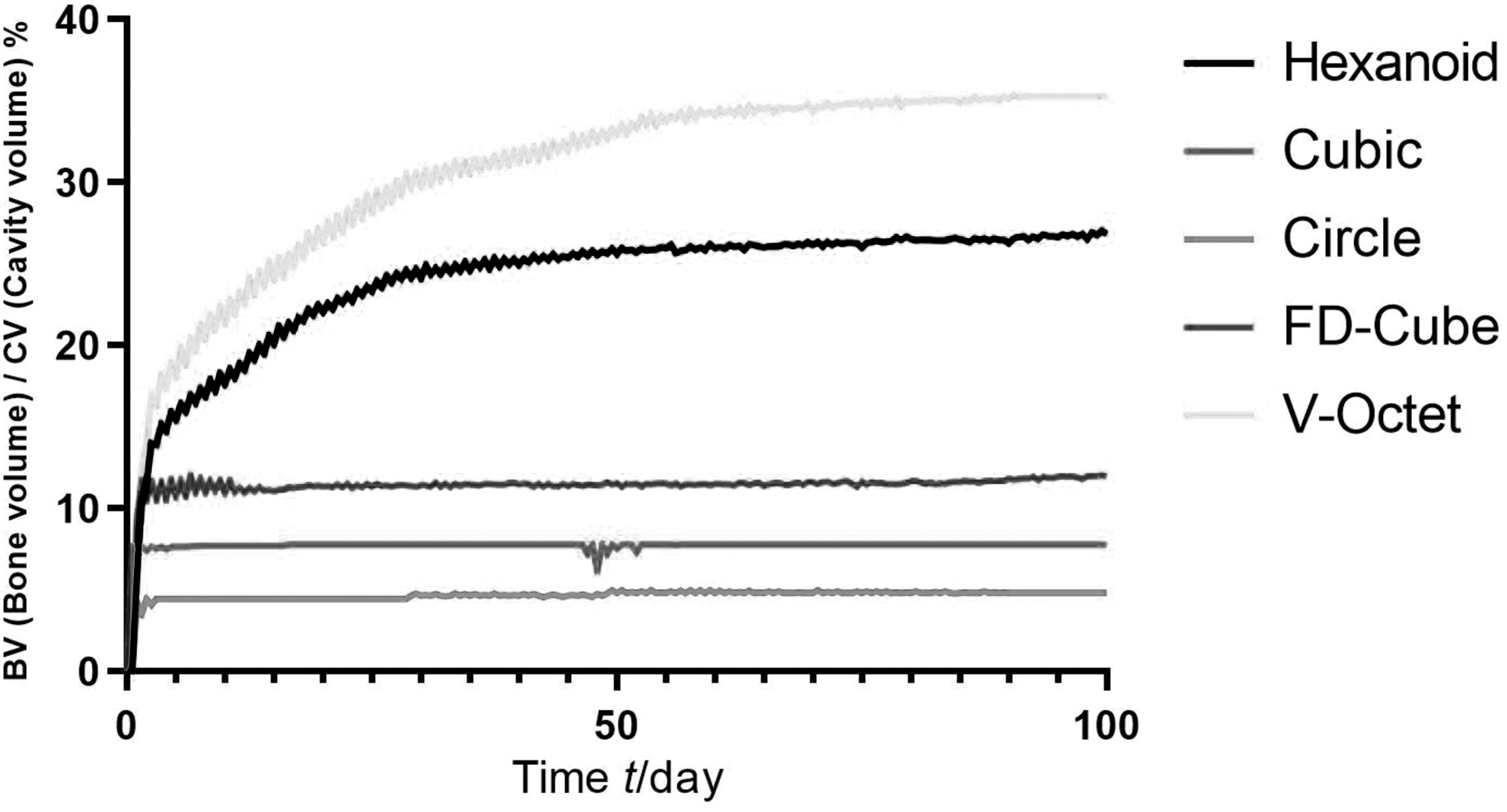
The relationship between the BV (Bone volume)/CV (Cavity volume) and Time (day) of five architecture scaffold designs.
Bone ingrowth distribution
Osteogenesis within the scaffold cavity at different time points is illustrated in Figure 6. In general, regardless of the scaffold architecture, bone growth was observed to initially occur along the scaffold surface, followed by further infiltration toward the central cavity region, as regions with high SED act as the main driving force for bone remodeling. The distribution of bone growth reveled that bone occupied more space near the bottom surface of the scaffold and less growth occurred in the upper cavity, resulting in nonuniform bone remodeling within each scaffold unit cell under similar mechanical boundary conditions as the in vivo condition. Among all scaffold designs, more bone growth was observed in the Hexanoid and V-Octet scaffold cavities at the conclusion of the simulation (100 steps).
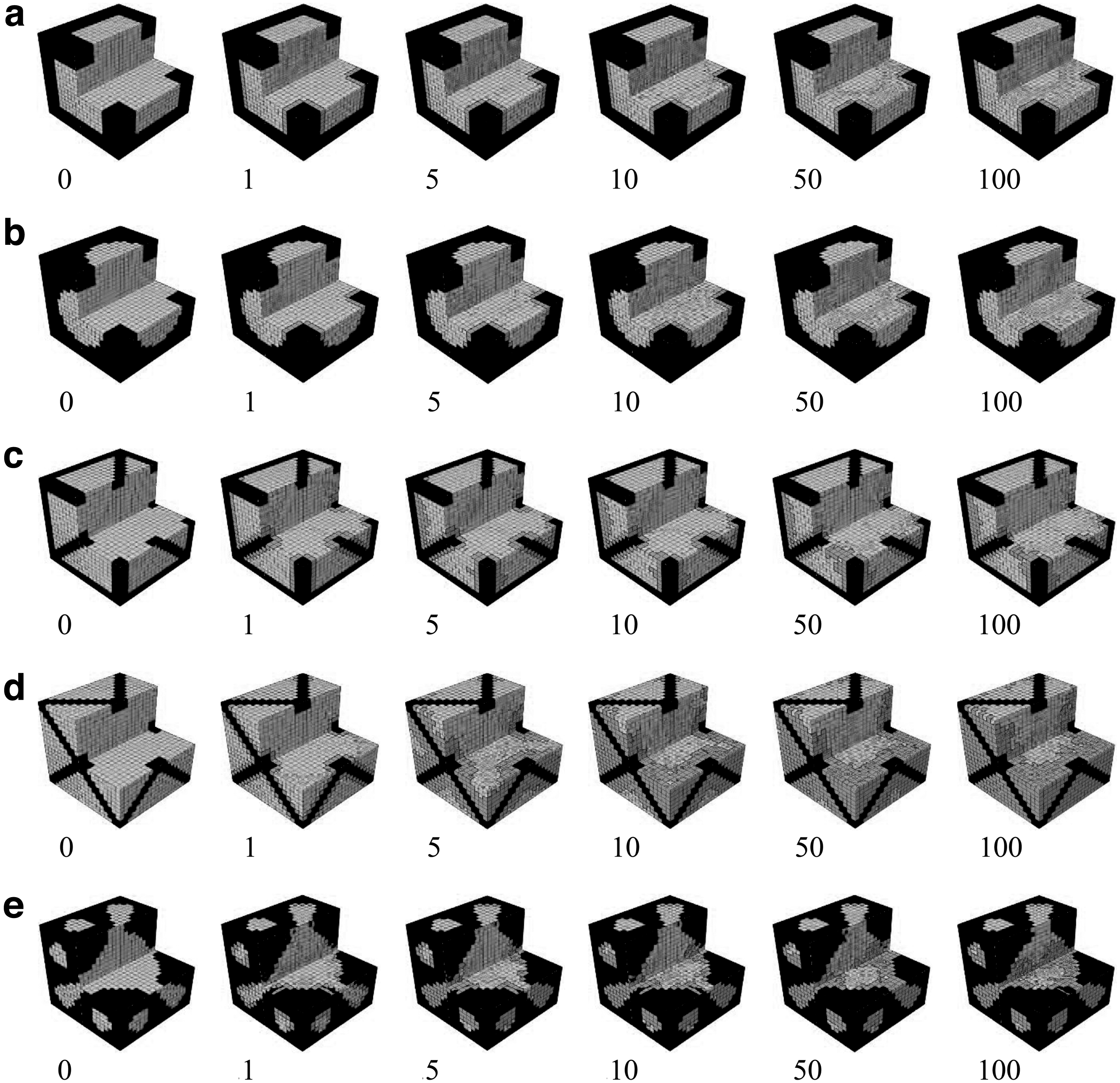
The bone ingrowth situation of the five scaffold designs:
Scaffold mechanical compression test and simulation
The stress versus strain curve of real compressive testing is displayed in Figure 7, and Young's modulus of two specimens is summarized in Table 2, which was adapted to the bone implant application. Below the strain of 0.8% (I), the scaffold specimen could be considered performing elastically, while the plastic region (II) started until the strain reached 1.6%. After yielding, struts failed successively (III) but strength was preserved, and plastic hardening still occurred until a major fracture (IV). The insignificant error between the elastic properties of the two tested specimens indicated a successful and repeatable processability for this structure. However, compressive testing on two specimens indicated that the first strut fracture could have a different impact on the structural integrity. It could be expected that the first strut fractures could lead to structural instability and the final fracture of the truss architecture. Thus, these results indicated that operating under the (I) region was essential to avoid catastrophic failure of the component when loaded in compression.

The Stress versus Strain curve of the real compressive testing of 4 × 4 × 6 Ti64 Hexanoid scaffold specimen.
The Mechanical Properties of Two 3D Printed Ti64 Scaffold Specimens and 5 Finite Element Analysis Scaffold Models
Strain at first strut fracture only applicable in real mechanic tests, FEA simulation didn't include scaffold fracture stage.
FD, face-diagonal; V-Octet, Void Octet.
The stress–strain relationship of each scaffold design was analyzed and is presented in Figure 8 based on the simulation results obtained through the Abaqus software. The data indicated that among all scaffold designs, the cubic structure scaffold displayed the highest Young's modulus and greatest yield strength, whereas the V-Octet scaffold had the lowest values. The remaining three scaffold designs displayed relatively similar mechanical strengths. The calculated Young's modulus of the Hexanoid, Cubic, Circle, FD-Cube, and V-Octet scaffolds based on their performance in the elastic region were found to be 9.34, 17.70, 10.41, 6.49, and 4.85 GPa, respectively. It was noted that there was a minimal difference (20%) between the real compressive testing data and the simulation results for the Hexanoid scaffold, which validated the accuracy of the simulation method. The simulation results can therefore be used for qualitative comparison of the mechanical strengths of different scaffold designs.

The Stress versus Strain curve of the compressive testing simulation of Hexanoid, Cubic, Circle, FD-Cube, and V-Octet scaffold.
Discussion
The most important findings of the study are that the Hexanoid exhibited favorable biological and mechanical behavior within this model and compared favorably to the other scaffold designs. The V-Octet demonstrated the greatest amount of bone formation within the in silica modeling, while the Hexanoid was the next best performing scaffold in this regard. However, the V-Octet design had the lowest yield strength on mechanical testing, while the cubic scaffold had the greatest yield strength and was in effect twice as strong as other three designs, including the Hexanoid.
The conventional scaffold designs all exhibited other unique characteristics. The cubic design, with its square-shaped pore structure, is known to possess high mechanical strength and an adequate level of porosity, but it also has a high concentration of geometrical stress.34,35 On the other hand, the circular bone scaffold design benefits from reduced stress concentration points, improved resistance to fatigue damage, and a greater Young's Modulus.36,37 These two basic and conventional designs were included in our comparative study as a reference for performance. Two beam-based lattice scaffold structure was designed by Egan, 23 which can rapidly and systematically configure a lattice's structure for multiple controlled properties simultaneously. One is FD-cube, which retains the cube cell beams and adds a diagonal beam on each face, a feature for the lowest surface–volume ratio. This topology achieves the highest elastic modulus for a given porosity while retaining a high permeability but has a low shear modulus and surface–volume ratio.
The other is a V-Octet design, which belongs to the Octahedron family, and features the highest surface–volume ratio. The Octet topology has a relatively high shear modulus and surface–volume ratio, but low permeability that may be favorable when tissue growth conditions are not limited by scaffold stiffness and nutrient transport. 23
Dynamic bone growth within different scaffold architectures has been investigated and modeled by coupling the boundary condition and the bone remodeling theory. Within the V-Octet designed scaffold unit cell, growth bone occupied more of the cavity space, but this design sacrificed mechanical rigidity. Among five different scaffold architecture designs evaluated in this study, the novel Hexanoid continuously curved scaffold unit cells achieved better balance in both stimulating bone ingrowth and maintaining structural properties. Unlike conventional truss configurations based on simple and flat cubic or honeycomb lattices, the novelty of Hexanoid scaffold reflects in its periodic concave surfaces and provide a minimal surface geometry. Minimal surfaces, which arise naturally in response to mechanical surface tension, reduce geometry-induced osteoblast sheet surface tension, thereby enabling osteoblasts to respond to bone mechanical stimulation more effectively. Previous in vitro experiments, which indicated two important observations are that the rate of bone tissue regeneration increases with curvature, and that bone tissue regeneration favors concave surfaces compared with either convex or planar surfaces.38,39
This phenomenon was subject to mathematical modeling by Sanaei et al. 40 In another complementary in vivo investigation by Scarano et al., similar findings were deduced from the study involving hydroxyapatite-coated Ti-6Al-4V alloy bone scaffold implants. They found that the stem cells challenged with concave surfaces differentiated quicker and showed nuclear polarity, an index of secretion, cellular activity, and matrix formation. 41 These findings were further substantiated by the outcomes of FEA in the present study. The Hexanoid architecture also contains embedded linear elements, enhancing its mechanical integrity. Other orthopedic implants based on continuous embedded linear elements also confer satisfactory structural stability under appropriate design.42,43 The evaluations of previous literatures have been compared and summarized in Table 3. Other traditional scaffolds may have manufacturing convenience, but the angular and sharp structures result in concentrated stress distribution, which may locally benefit osteogenesis in specific regions of the scaffold but is not conducive to overall bone growth throughout the cavity.
The Bone Growth Simulation Evaluation and Mechanical Properties' Evaluation of Scaffold Structural Geometry in Current Study and Previous Literatures
CAD, computer aided design; FEA, finite element analysis; HA, hydroxyapatite; PLA, polylactic acid.
The unique geometry and robust design of the Hexanoid scaffold, incorporating a periodic curved surface and alternative minimal surface, provides several advantages. First, its continuously curved surface remains consistent even after replication during manufacturing, distinguishing it from other scaffold designs with sharp angles and edges. Second, this design allows for multidimensional precision optimization of porosity, surface area, and curvature shape to resemble normal bone architecture more closely and potentially imitate trabecular bone structure under various physiological and pathological conditions. Furthermore, it is expected to possess adequate mechanical properties to withstand anticipated physiological loads. The ability of the Hexanoid scaffold unit to stimulate bone ingrowth was evaluated and compared with that of traditional designs, and it performed better than all but V-Octet design.
The compressive testing and FEA simulations provide further insight into the mechanical performance of scaffolds as implants in the human body. The cubic structure scaffold exhibited the highest compressive strength, which can be attributed to its larger interface area and regular architectural shape. However, a higher Young's modulus for this scaffold does not guarantee its mechanical properties are suitable for use as an implant. The average Young's modulus of trabecular bone measured mechanically is 10.4 GPa (standard deviation 3.5), 44 while the Young's modulus for the Cubic scaffold determined in this study was nearly twice that value. All four of the other scaffold designs as tested under these conditions exhibited Young's moduli very closely approximating that of normal trabecular bone. To avoid stress shielding and the subsequent degradation of surrounding bony tissue, it is crucial for nonbiodegradable scaffolds to have mechanical properties like those of real bone. In this regard, the Hexanoid, Circle, and FD-Cube scaffolds were all considered to have appropriate compressive mechanical strength.
Wang et al. conducted a study to investigate the bone ingrowth capabilities of cubic scaffold designs made of biodegradable and nonbiodegradable materials. In their simulation, the bone tissue within the biodegradable cubic scaffold underwent two periods of significant growth before reaching the remodeling steady state. The second period of remodeling was associated with the scaffold's dissolving process, during which the strain energy that was previously shouldered by the scaffold was transferred to the bone tissue, thereby stimulating its further growth. 22 In contrast, the titanium scaffold only showed one obvious growth period before reaching its maximum limit, which can be attributed to stress shielding. As the scaffold was not biodegradable, further external mechanical pressure was unable to reach the bone tissue itself. Although titanium scaffolds are unlikely to maintain optimal conditions for bone ingrowth after implantation, they may provide sufficient mechanical strength to enable physiological weight bearing as a component of early rehabilitation. Besides, it may be clinically challenging to matching bone ingrowth rate with dissolve rate of biodegradable scaffold.
The findings of our in silico study on nonbiodegradable scaffolds suggest that the 1st month of rehabilitation exercises would play a crucial role in promoting bone growth. Optimal bone remodeling is subsequently obtained in our simulation by adopting a moderate exercise intensity, as the efficacy of mechanical stimulations on bone growth tends to decline. Importantly, the rehabilitation regimen should be tailored to the scaffold architecture and its material properties, as these factors can significantly impact the bone growth outcome.
In silico studies of bone growth in porous scaffolds require realistic data on applied loads, implant–bone geometry, and the mechanical properties of the tissue to predict the evolutionary process of bone remodeling quantitatively and accurately. Our study includes several simplifications and assumptions to save simulation time and reduce model complexity, and therefore important limitations need to be evaluated. First, it was assumed that mechanical SED is the sole stimulus for bone remodeling. The growth rate c as an empirical constant in Equation 1 was selected, whereas actually, the growth rate is related to the biochemical and molecular signals, which regulate the activities of osteoclasts and osteoblasts. 28 However, the present scaffold–bone model did not consider these other critical factors. Second, the real walking frequency was generally treated as the mean loading history of every day due to the computing cost. The actual gait pattern of a patient with fracture undergoing rehabilitation would be influenced by pain restriction of joint motion and did not represent the boundary condition setting.
In addition, a single unit block cell was used to represent a macroscopic scaffold implant to simplify the model, and the model does not account the unit-to-unit interaction and therefore lacks the ability to define effects related to the overall scaffold geometry on tissue growth. Single face compressing boundary condition also results in nonuniform bone remodeling distribution within each scaffold unit cell. Finally, the ISF was considered as an incompressible solid instead of a fluid, which neglects the important role of the fluid shear stress between the ISF and bone tissue.19,45 Therefore, further studies are needed to generate more complex and realistic models that consider the multiple other factors affecting bone remodeling. Those factors may include fluid flow, nutrient transport, and even cell behavior. Further in vivo studies and controlled trials are ultimately needed to validate the accuracy of the simulations and ensure that the results obtained from the simulations are consistent with clinical outcomes.
Despite these limitations, the current study provides an important starting point for understanding the relationship between scaffold architecture and bone ingrowth and could potentially lead to further advance in bone tissue engineering that are critical for skeletal reconstruction.
Conclusion
This finite element model provided a platform to predict and screen for unit cell architectures considered here that best encourage bone growth within the scaffold pores, potentially reducing the number of experimental studies necessary to validate design performance. In comparison with other more conventional bone scaffold unit structures, the novel Hexanoid scaffold design achieved a better balance between bone ingrowth stimulation and robust mechanical strength. Despite some limitation during simulation, our results suggest this design has great potential for conducting further in vivo experiments or clinical trials. Validating this model experimentally would next involve implanting the scaffold into a bone defect in an animal model and making histological investigations of tissue phenotype at various defined time points to evaluate bone ingrowth.
Footnotes
Acknowledgments
N.S. would like to acknowledge the Translational Research Institute (TRI). The Skyscan 1272 μCT used in this research was purchased by the Mater Foundation using funds donated by the Lions Club of Australia. A partial version of our study has been released on Research Square. This allows us to share our work in advance, gather feedback from the community, and make necessary article adjustments before undergoing peer review in a journal. You can find the preprint here: Yuheng Wang, Luping Wang, Nicolas Soro, et al. Bone Ingrowth Simulation within a Novel Microstructure Scaffold, March 20, 2023, PREPRINT (Version 1) available at Research Square [
Authors' Contributions
D.E. and Z.L. devised the project, the main conceptual ideas, and proof outline. Y.W. worked out almost all the technical details and performed the bone ingrowth simulation for the suggested experiment. L.W. worked out the coding of bone growth theory. N.S. and K.T. proposed and conducted the scaffold mechanical compression experiments, and provided the stress–strain curve figure. P.R.B. reviewed the article and gave valuable advice for writing and formatting. N.G. provides the parameter drawing of scaffolds. The article was mainly completed by Y.W. with input from all authors.
Availability of Data and Materials
Author Disclosure Statement
The authors have no relevant financial or nonfinancial interests to disclose. The authors have no competing interests to declare that are relevant to the content of this article.
Funding Information
All authors certify that they have no affiliations with or involvement in any organization or entity with any financial interest or nonfinancial interest in the subject matter or materials discussed in this article. The authors have no financial or proprietary interests in any material discussed in this article.