
Abstract
In addition to the well-documented resource efficiency and geometrical freedom, Digital Fabrication (DFAB) revolutionizes architecture by integrating functionalities into building elements, unlocking untapped potential from the micro- to the macroscales. This study uses binder-jet printed sand for a DFAB prototype—Fireplace2—tailored for indoor heating. Named after its traditional counterpart, Fireplace2 showcases DFAB’s prowess in crafting precise microclimates for heightened thermal comfort. Our research, tuning mechanical and thermal properties across micro and meso scales, illustrates DFAB's utility in architects' hands for crafting tailored microclimates. This approach manipulates the effective thermal conductivity and macroscale topology for stability against toppling (0.8 kN). A vertical infill porosity gradient establishes a surface temperature gradient, countering ventilation-induced thermal gradients. With a minimal operational temperature vertical gradient (+0.2°C), complying with international comfort standards (Predicted Mean Vote −0.23, People Dissatisfied 6%), Fireplace2 stands testament to DFAB’s microclimate-shaping capabilities despite challenges like foot-level ventilation. The study propels DFAB into a sustainable paradigm, aligning occupant comfort with environmental consciousness, thereby fostering more efficient and enjoyable indoor spaces.
Introduction
Digital Fabrication (DFAB) has established itself as a feasible design-to-production workflow in architecture and building construction. DFAB refers to using digital technologies such as computer-aided design (CAD) software and computer-controlled fabrication equipment to design and build architectural components, structures up to entire buildings.1,2 It enables highly customized and complex shapes with greater accuracy, efficiency, and cost-effectiveness than traditional manual methods. There is great interest in the fabrication of sustainable building elements due to the ability to combine form and functionality in a single material manufacturing process.
State-of-the-art research3–6 demonstrated building elements with single performance characteristics, mostly related to structural stability, reducing material usage, improving sustainability, construction efficiency, and cost-effectiveness. Recently, researchers have explored using DFAB to integrate energetic functionality, such as thermal,7–9 optical,10–12 acoustic,13,14 ventilation,15,16 and carbon sequestration17–19 into architectural elements and building structures. We name such elements multifunctional, and the process performance-integrated DFAB. The goal of performance-integrated DFAB is to produce integrated, multifunctional (structure and heat- and mass-transfer) building elements that reduce simultaneously material embodied and operational greenhouse gas (GHG) emissions of buildings. Research, which we cite above, have developed DFAB systems by integrating energy dissipating elements, such as hydronic heating/cooling, ventilation networks, and photovoltaic panels. However, most performance-integration DFAB research has (i) neglected to tune the material characteristics during the DFAB process to enhance performance; and (ii) combine this with the geometric freedom of DFAB in a multiscale approach.
A multiscale approach is demonstrated to integrate thermal and mechanical functionality into DFAB structures, with the functional goal of using such structures to absorb, store, and dissipate heat. We use a material–process combination of sand particles and binder-jet printing to achieve this. The high specific heat capacity of sand would make the DFAB structure less susceptible to rapid changes in temperature, and allow it to store heat and maintain a consistent temperature over extended durations.
Materials and Methods
We tune the thermal (conductivity and heat capacity) and mechanical (compressive strength and toppling force) of the structure on multiple scales, namely the (1) microscale manipulating the binder-jet printing parameters and using postprocessing, (2) mesoscale using intricate 3D printed geometries, and the (3) macroscale using the topology of the structure.
The definition and application of the micro-, meso-, and macroscale can vary depending on the context and field of study. In this study, we employ the terms to characterize different levels of analysis and observation. At the microscale, we focus on the materials’ fine details and mechanical and thermal properties on a small scale, typically <0.1 mm. The mesoscale, intermediate between micro- and macroscales, comprises geometrical analysis, typically <1cm. Finally, the macroscale refers to the larger-scale analysis, capturing the overall behavior of the assembly.
Tuning the microstructure of binder-jet printed sand components
Binder-jet 3D printing 20 is a popular Additive Manufacturing (AM) technique that involves fabricating a solid structure from a 3D model by layer-on-layer addition of alternating powder material and binder. The printer spreads a thin (typically <500 µm) layer of powdered material across a build plate. The print head jets a liquid binder on the powder surface. The sliced cross-section of the geometry determines the print head’s movement and hence the deposited binder’s location. The printer uses heat treatment to harden the binder before applying the next powder layer. At the end of the printing process, the printer operator can remove the unbound sand to reveal the 3D printed structure. Several industrial processes ranging from automobile21,22 to architectural23,24 applications, use binder-jet 3D printed structures to fabricate parts with intricate or complex geometries at different scales cost-effectively. The fabricated parts can either be used directly or as casting molds.
To fabricate thermally activated structures for indoor heating, we used recycled sand as the powder material (silica) and an organic phenol-based binder with an industry-grade binder-jet 3D printer (Voxeljet VX1000). Researchers have performed extensive testing on the material (cementitious powder, mortar, fibers), fabrication (nozzle geometry, speed, particle, and layer dimensions), and postprocessing (coating and curing) for binder-jet printing processes.25–31 We chose sand for its thermal properties, low cost, and recyclability.
In this section, we have summarized the process of binder-jet printing, relevant parameters, preparation, information on materials, and particle/layer dimensions below. These details were intentionally summarized because we addressed them in detail in an earlier publication. 32
Figure 1 holistically captures the fabrication journey, from the printing process to detailed structures and the subsequent effects of postprocessing, offering an insight into the material’s properties for potential construction applications. To enhance the architectural applicability of binder-jet 3D printed sand, microstructural adjustments were necessary. Unprocessed binder-jet 3D printed sand exhibited mechanical weaknesses (compressive and flexural strengths below 5 MPa) rendering it unsuitable for architectural use. In response, our design decision involved postprocessing techniques to strengthen the microstructure. This step aimed to significantly improve the mechanical properties of the sand elements, ensuring they meet the requisite strength standards for architectural components. The microstructural tuning is a critical aspect of our design strategy to address the limitations of unprocessed binder-jet 3D printed sand. In the aforementioned study,
32
using statistical experiments, we found that postprocessing techniques and materials can significantly enhance the thermal and mechanical properties of binder-jet printed sand parts. Epoxy infiltration and curing, compared with unprocessed samples, resulted in a 580% increase in flexural strength and a 2,063% increase in compressive strength. Thermal conductivity and specific heat capacity improved by 671% and 20%, respectively. No thermal decomposition was observed for unprocessed or postprocessed samples up to 200°C. For the particular combination of binder (phenol-based) and infiltrate (high-temperature Epoxy), five unique postprocessing temperature–duration combinations were tested for the mechanical and thermal characteristics, and Equation 1 was used to generate the statistical model (Fig. 1F and G).
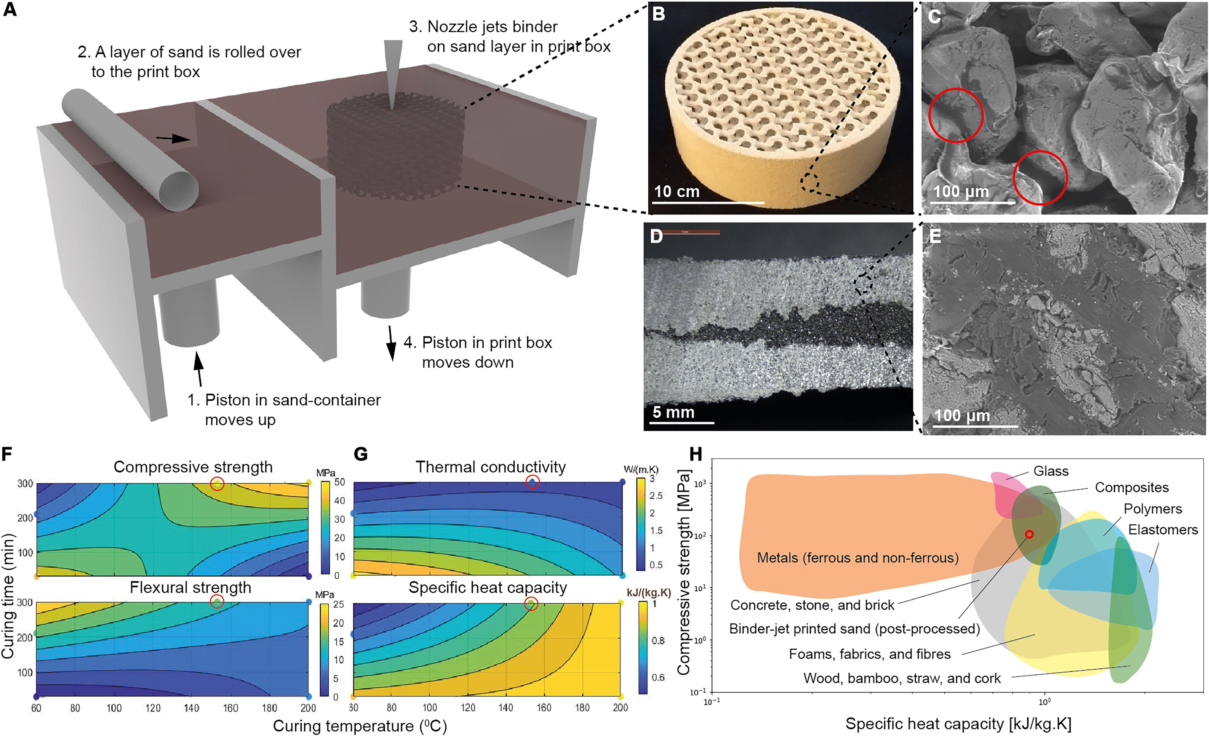
The 3D-Printed Sand Fabrication Process. Illustrating the binder-jet printing process,
The model resulted in an acceptable model fits (how well the regression model fits the observed data) R2 > 0.9, crossvalidation (how well the model can predict the response variable for new, unseen data) Q2 > 0.9, and replicability Rep = 1.0 for the mechanical performance. However, the performance of the model for the thermal performance was not satisfactory and requires a separate unique model, and more data points for each of the measured thermomechanical characteristics. The chosen postprocessing parameters, 150°C and 300mins, are highlighted in Figure 1F and G. The curve fitting and data analysis were made publicly available. 32 The microstructure of the samples before and after postprocessing is shown in Figure 1C and E, with the mechanical and thermal performance maps shown in Figure 1F–G. In our analysis, we conducted thermogravimetric (TGV) measurements on the samples up to 200°C. The postprocessed samples did not exhibit any decomposition or outgassing. However, it is important to note that further long-term studies are necessary to understand the effects of aging on the samples. These studies will provide a more comprehensive evaluation of the samples’ performance over extended periods. Postprocessed sandprints’ improved mechanical and thermal properties make them suitable for our target application and comparable to other composite materials, as shown in Figure 1H.
This study used sand and a phenolic organic binder to fabricate the structure due to their availability. To enhance the structure’s performance, epoxy was applied as a postprocessing step. However, it is noteworthy that the field of binder-jet printing and 3D printing for building construction is progressing toward sustainable, noncementitious materials. Recent research and applications use eco-friendly binders that offer sufficient strength without the need for extensive postprocessing.24,33–35 Additionally, the microscale porosity of the printed elements is a critical parameter that affects the mechanical performance of printed elements, 27 was not measured, and should be considered in the future.
At the microscale, we tuned the physical properties of the binder-jet printed sand elements to achieve desired thermal capacity and compressive and flexural strength. Next, at the mesoscale, we explored the effect of geometry on heat transfer.
Tuning heat transfer through mesoscale infill structures
Having reinforced the mechanical and thermal properties of binder-jet 3D printed sand through microstructure tuning, our focus shifted to achieving a customizable thermal microclimate in our final application. Recognizing the need to easily tune the effective thermal conductivity of sand prints for precise and customizable surface temperatures, we directed our attention to the mesoscale. In this study, we strategically manipulated the geometrical infill structures. This decision arose from the overarching goal of countering potential discomfort elements and establishing a bespoke thermal environment. The significance lies in the ability to not only enhance material strength but also to precisely control the thermal behavior, offering architects a tool to craft tailored microclimates and enhance thermal comfort in diverse indoor environments.
To refine the thermal properties at a mesolevel, we manufactured infill geometries inspired by sandwich panels and lattice structures. We conducted dynamic measurement tests using a surface probe to evaluate the impact of weight-normalized mesoscale porosity on thermal conductivity (Supplementary Data S1).
Figure 2 describes the thermal intricacies of different infill geometries, essential for understanding heat dynamics in structures fabricated through diverse DFAB methods. We started by creating prototypes of infill geometries using polylactic acid (PLA) samples with cubic, gyroid, and random infills. These prototypes were fabricated using a commercial fused filament fabrication (FFF) printer (Ultimaker 2+). We printed and tested ten samples for each infill structure, varying the infill percentage from 10% to 100%. We used volumetric mesoscale porosity (
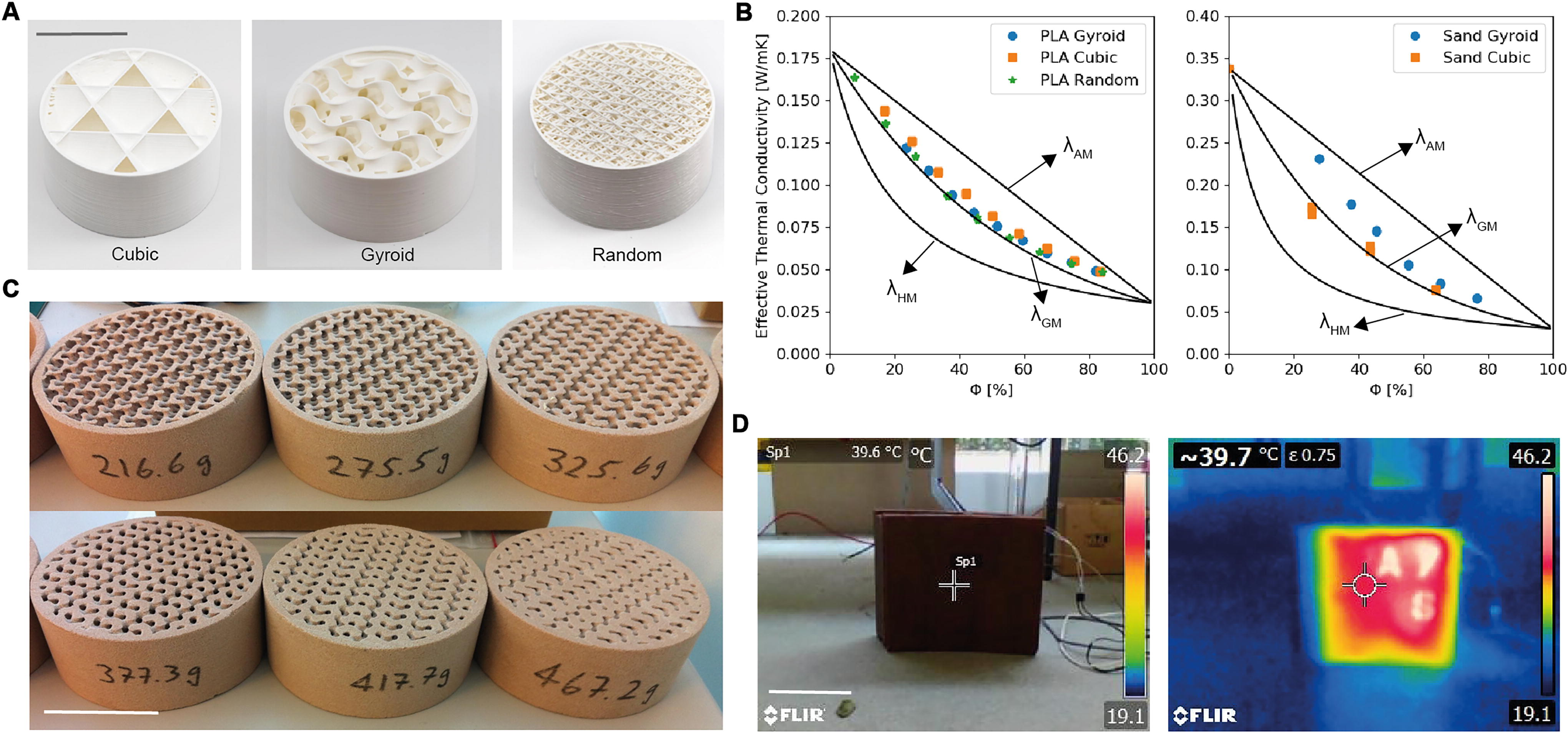
Thermal Behavior of Varied Infill Geometries. Highlighted are diverse infill structures within 3D-printed polymer samples using FFF in
In the case of the binder-jet print sand infill structures, we use the following approximation.
The thermal conductivity measurements were within the theoretical range of minimum (
Infill porosity was the determining factor for thermal conductivity in all infill geometries, with no significant impact from geometry. We maintained the thermal conductivity of PLA at 0.175W/mK37,38 and air at 0.028W/mK. 39 We repeated the experiment using binder-jet printed sand structures with gyroid (Fig. 1C) and cubic infill structures. Structures with high infill porosity (0.8) were challenging to fabricate due to low mechanical strength. In comparison, structures with low infill porosity (0.2) were difficult to measure because of the difficulty of removing all the sand. As a result, we printed and measured samples with infill porosity ranging from 0.2 to 0.8. We measured the thermal conductivity of a solid block of binder-jet printed sand at 0.34W/mK and maintained the air’s thermal conductivity at 0.028W/mK. 39
We demonstrate an application of selective heat transfer using variable infill porosity in a 300 mm × 300 mm × 150 mm sand-printed element in Figure 2D (Supplementary Video S1) with a spatially varied cubic infill pattern. Regions with lower infill porosity (0.0) transferred more heat from an internal heat source to the surface than regions with higher infill porosity (0.7). In the following section, we build on this prototype to show a macroscale heat transfer application.
Application and Results
Installation of the Fireplace2: Macroscale application for space heating
In this study, we describe the design and construction of a scalable, self-supporting, heat-emitting sand structure assembling several elements based on the prototype shown in Figure 2D. The Fireplace2, as we named it, is an indoor space heater that provides customized and localized thermal comfort. With the thermomechanical properties successfully tuned, we finally focused the design to ensure the practicality of the Fireplace2 prototype. Emphasizing ease of assembly, disassembly, and the critical need for a self-supporting structure capable of withstanding user-induced toppling forces, we designed a macroscale double-curvature geometry. The use of a modular assembly system, elaborated below, further reinforces the prototype’s stability and user-friendly design.
The Fireplace2 was designed to be modular and portable, easily assembled, disassembled, and transported. It consists of 18 elements, each 300 x 300 mm, with varying thicknesses. Each element has three components (as shown in Fig. 3A): (1) the surface texture, which conveys the surface temperature to the user, (2) a 5 mm-wide cubic infill porous layer with variable porosity to achieve a specific thermal conductivity, and (3) a 10 mm-wide low-infill (30% porosity) gyroid insulation layer. The variable thermal and insulation porosity layers are separated by a 5-mm slot for the heating element. The goal of the insulation layer is to minimize heat losses to the back of the Fireplace2 structure.
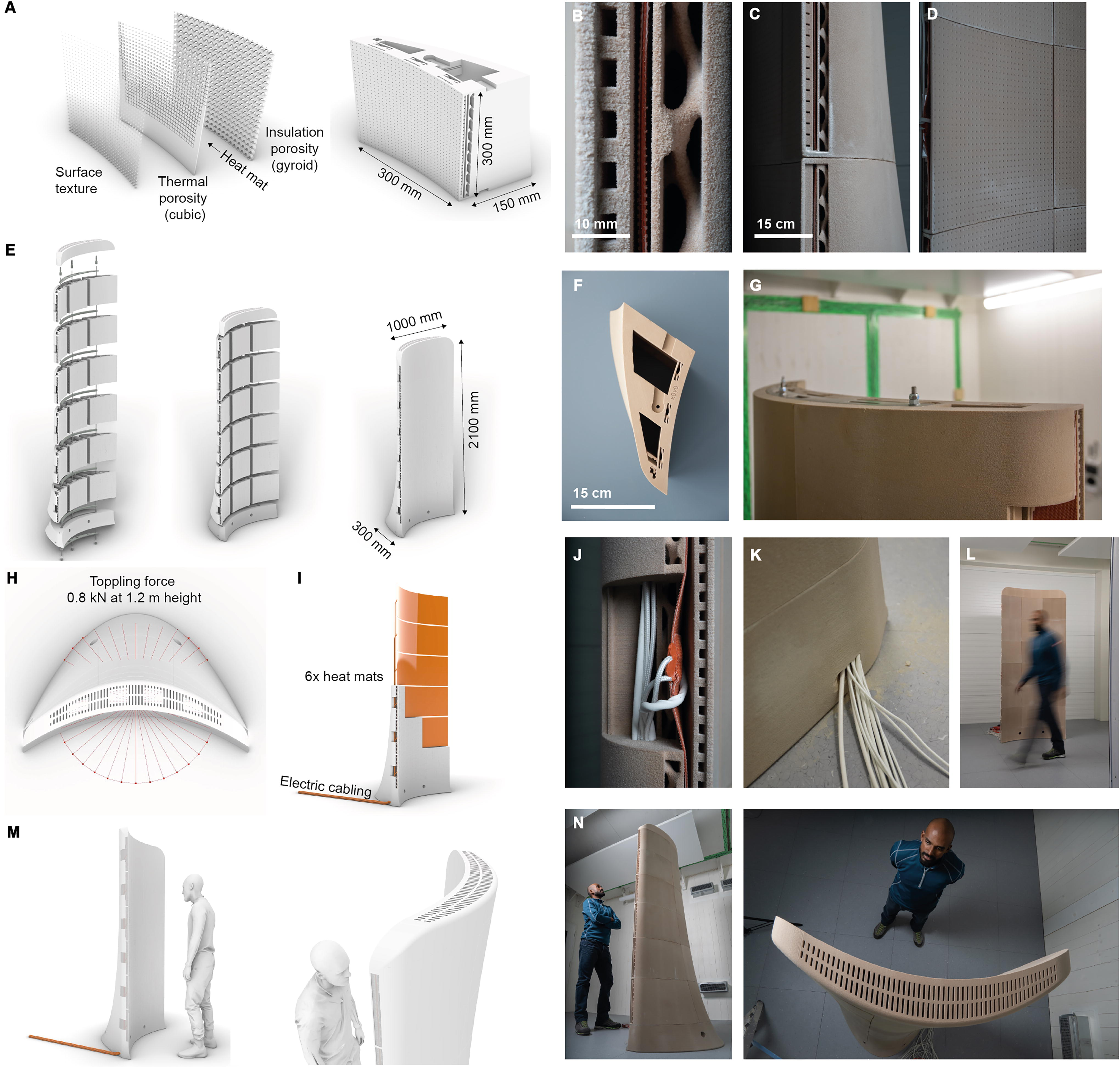
Rendering and construction details of Fireplace2.
We engineered the structure’s topology, front-to-back, and top-to-down curvatures to reduce the risk of toppling (Supplementary Data S2). Considering a standard 0.8 kN force typically applied to handrails in buildings 40 at the height of 1.2 m, we minimized the toppling moments from the front of the structure (as shown in Fig. 3C). In the absence of specific standards tailored to stand-alone heating elements, we opted for a well-established standard applied in structural design to ensure a reasonable basis for evaluating stability. Increasing the number of elements in each row can also decrease the risk of toppling when force is applied from the back.
Starting with a single sand-printed base, we assembled 18 elements into a single structure and completed it with a single top. A stainless steel connector laterally held each row of elements at the top and bottom. We used a post-tensioning mechanism of steel cables running through each column, fastened at the top and bottom elements. The lateral connectors and tensioning elements provide additional strength and stability to the structure, helping it to resist external loads and deformation over its lifetime. We completed the assembly with a grill cover at the top of the structure, which hides the post-tensioning screws. The grills allow warm air within the structure to be ventilated into the room. The assembly is shown in Figure 3B and Supplementary Video S2.
We placed 1000 mm × 300 mm × 2 mm silicon heating mats (Keenovo 230V, 1500W) in each row by passing them through the slot in the adjacent elements. A k-type thermocouple was embedded on the front surface of each mat to monitor and regulate the surface temperature. The wiring was concealed within the sand elements and exited the structure’s base, as depicted in the assembly details and photos in Figure 3. We installed a PID controller to keep all heat mats at a constant temperature.
Occupant thermal comfort measurements
Fireplace2 is designed to function as an indoor space heater. The structure’s large surface area allows it to operate at lower temperatures while providing sufficient heat. The Fireplace2 offers the same cozy ambiance and localized thermal comfort as a traditional fireplace within low-temperature, high-efficiency heating systems powered by renewable energy sources. Notably, compared with its namesake, the large surface area and lower operational temperatures render it suitable for integration into indoor environments as a standalone unit or as a part of a 3D-printed wall element. In this section, we demonstrate how we can adjust the surface temperature gradient of Fireplace2 by utilizing the variable porosity layer of the structure.
Current models41–45 and standards46–50 on thermal comfort include parameters such as temperature, relative humidity, air velocity, and factors such as clothing and occupant behaviors. Research has also shown that significant differences in temperature between different heights can lead to discomfort for occupants.51–54 Recent studies have examined the effect of the magnitude of temperature gradients and the extent of discomfort, exacerbated indoors by ventilation strategies that create lower temperatures at the feet level and higher temperatures at the head level because of air buoyancy.55–57 However, tuning both air and radiative temperatures (as a result of temperatures of visible surfaces) play a role in determining thermal comfort. 58 By adjusting the surface temperature gradient of the Fireplace2, we can address these issues by increasing the radiative temperature to compensate for the low air temperature at the feet level and reducing the radiative temperature to address the high air temperature at the head level.
Figure 4 describes the thermal performance of the Fireplace2, crucial for understanding its operational dynamics and potential applications in real-world scenarios. Figure 4A shows the installation inside a 5.0 m × 5.0 m × 3.0 m room. The room has a constant fresh air supply and exhaust (Supplementary Data S3). The heat mats were programmed to maintain a set point of 55°C, and the system remained running for 24 h to achieve a steady state. Figure 4B–D shows the surface temperature of Fireplace2 when operating the heat mats at a constant setpoint of 55°C. Due to its thermal capacity, Fireplace2 retains heat long after it is turned off (Supplementary Data S3). During operation, we observed mean surface temperatures ranging from 50°C to 40°C for the six rows of vertically mounted sand-printed elements between 0.15 and 2.05 m from the ground. Figure 4C illustrates the infill porosities relative to the height of the structure. The difference in surface temperatures is closely correlated with the infill porosity gradient of the structure. Overall, the measured surface temperatures align well with the analytical model from Equation 1, which correlates effective thermal conductivity with infill porosity.
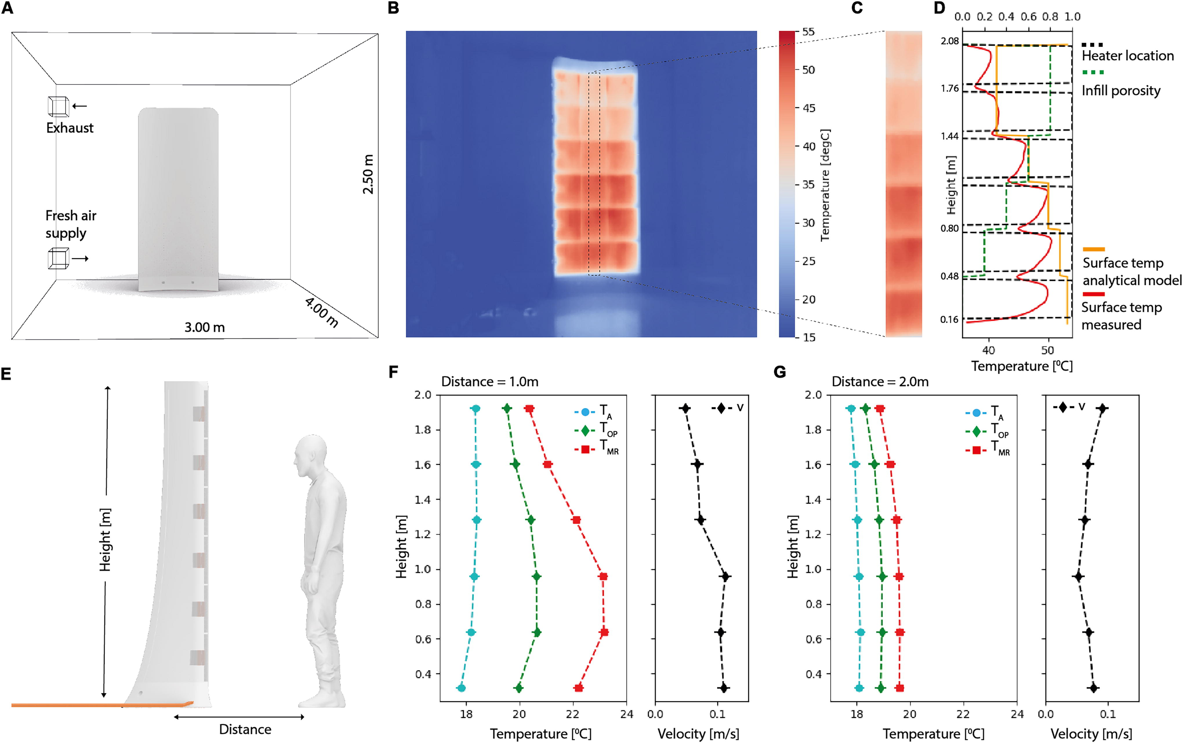
Thermal Performance of Fireplace2. Illustrating the experimental setup within the test chamber, encompassing air supply and exhaust locations
However, we noted that the bottom two rows exhibited lower surface temperatures than predicted by the model. This discrepancy may be attributed to two potential factors. First, the proximity to the ground could lead to conduction losses, affecting heat transfer. Second, the convective effects of the ventilation system might influence the surface temperature. To gain a deeper understanding, a Computational Fluid Dynamics (CFD) model/analysis is required in the future to investigate these aspects. By incorporating this analysis, we plan to provide a more high-resolution perspective on the observed surface temperatures, their relationship to the infill porosity gradient, and the possible factors influencing the differences between the measured and predicted values and contribute to a better understanding of the performance of the assembly during operation.
We measured the air (T.A.) and operative (TOP) temperatures, and the air-velocity (vA) 1.0 and 2.0 m away from the structure (Fig. 4E–F) at the middle of each row of sand prints, that is, 0.32, 0.64, 0.96, 1.28, 1.60, and 1.92 m above the ground, respectively. The measurements were made using a calibrated Dantec ComfortSense measurement and data-acquisition apparatus. The accuracy of the air- and operative-temperature sensors are +/−0.2°C, and the air velocity sensor is 0.02 m/s. We calculate the mean radiant (TMR) temperature using the following formula:
59
TA, TOP, and TMR are the air-, operative-, and mean-radiative temperatures, and vA is the air velocity.
At 1.0 m distance from the structure, we observe a vertical T.A. gradient of −0.8°C (17.7 to 18.5°C) between the foot (0.32 m) and head (1.60 m) levels, respectively. The thermal porosity gradient of Fireplace2 (resulting in a surface temperature gradient) counters the T.A. gradient by achieving a TMR gradient of +1.2°C (i.e., 22.2 to 21.0°C) between foot and head levels, respectively. This results in an overall TOP gradient of +0.2°C (i.e., 20.0 to 19.8°C), reversing the T.A. gradient. The measurements comply with the ASHRAE Standard 55 50 comfort requirements (Supplementary Data S3) and achieve a Predicted Mean Vote (PMV) of −0.23 and a Percentage of People Dissatisfied (PPD) of 6%. At 2.0 m from the Fireplace2, the gradient and reversal are less significant, indicating a localized thermal comfort zone akin to the traditional fireplace.
In our experiment, we use temperature-controlled heat mats to show that the porosity of the 3D-printed elements affects how well the structure conducts heat. By adjusting the geometry of digitally fabricated building structures and surfaces, we can tailor their thermal properties at different locations and achieve the desired indoor thermal comfort profile. Of course, a temperature gradient in a room could be achieved in other ways. Our work, however, aims to demonstrate the potential of thermal performance integration in digitally fabricated building components.
Discussion and Outlook
In this study, we explored the application of binder-jet printed sand for digitally fabricating the Fireplace2 structure, designed to function as an indoor space heater and create a localized thermal comfort zone like a traditional fireplace.
The results show that the spatially varying mesoscale infill porosity of Fireplace2 resulted in a corresponding temperature gradient on its surface. This temperature gradient counteracts the typical thermal gradient induced by ventilation systems, leading to an operational temperature vertical gradient of only +0.2°C (20.0 to 19.8°C) between foot and head levels. The measured surface temperatures closely followed the simulated results and analytical model, validating the effectiveness of our approach. The assembly meets international comfort requirements and provides localized thermal comfort to building occupants.
This research opens exciting possibilities in DFAB for enhancing thermal comfort and energy efficiency in building construction. By employing multiscale geometry in binder-jet printed sand structures, we demonstrated the potential of DFAB processes to achieve specific thermal comfort. The design and fabrication of such assemblies and structures allowed us to achieve bespoke thermal properties, creating desired comfort zones. Such approaches can be extended to integrate similar DFAB techniques into building structures, enabling precise control of heat transfer and energy flows. These advancements have far-reaching implications for sustainable architecture, offering innovative solutions to improve occupant comfort while optimizing material/energy usage. By leveraging the capabilities of DFAB and embracing adaptable and customizable design approaches, we can create more energy-efficient, comfortable, and environmentally conscious indoor environments for the future.
Conclusion
In this research, a multiscale approach to Digital Fabrication (DFAB) has been effectively applied to design and fabricate a binder-jet printed sand assembly, known as the Fireplace2, for indoor space heating and localized thermal comfort.
The integration of microscale modifications in the binder-jet printed sand elements allowed for fine-tuning of mechanical and thermal properties using a statistical analysis approach. The effective thermal conductivity (λ) of binder-jet 3D printed lattice structures correlated well with mesoscale infill porosity (Ф) and was predicted using the weighted geometric mean approach (λGM). No correlation with the geometrical pattern was identified for cubic, gyroid, or random infills. The macroscale double-curvature topology was optimized to ensure stability against toppling for forces of up to 0.8kN. Individual elements were constructed and post-tensioned into the final 2.0 m × 1.0 m × 0.5 m assembly. The bottom-to-top vertical infill porosity gradient (0.0 to 0.8) in Fireplace2 closely matched the analytical model. Using a source temperature of 55°C resulted in a front surface temperature gradient between 50°C and 40°C. The surface temperature gradient successfully counteracted typical thermal gradients induced by ventilation systems. It resulted in a vertical bottom-to-top operational temperature (TOP) gradient of only +0.2°C (20.0°C and 19.8°C) measured 1.0m away from the structure. The assembly created a localized thermal comfort zone akin to a traditional fireplace. The performance of Fireplace2 aligns with international comfort requirements, achieving excellent thermal performance and occupant comfort. The Predicted Mean Vote was −0.23, and the Percentage of People Dissatisfied was 6%.
Further research is required to investigate several aspects, namely: (1) Explore alternative formulations of powder bed materials in binder-jet printing to expand material choices and optimize performance, (2) Conduct more high-resolution simulations (for example, Computational Fluid Dynamics analysis) to investigate the impact of multiscale heat-transfer physics on the overall thermal performance, and (3) more comprehensive thermal comfort analyses to optimize the DFAB process for various user requirements, space configurations, and ventilation systems.
Overall, this study highlights the potential of DFAB and binder-jet printed sand structures in addressing critical challenges in the construction sector, promoting energy-efficient, sustainable, and comfortable indoor environments. By addressing the proposed areas of improvement, future research can unlock even greater potential for this innovative technology in construction applications.
Footnotes
Acknowledgments
The authors thank the ETH Zurich Research Grant for funding this research. The authors also thank the following colleagues for their work in modeling, testing, and assembling the structure: Moritz Begle, Stefan Caranovic, Srinimalan Balakrishnan, Kaushik Dhanush Selva Ravi, Dr. Ole Ohlbrock, Dr. Davide Tanadini, Mauritz von Kardoff, Dominik Stoll, Dominik Vogel, Matthias Leschok, Dominique Maritz, Erik Jan de Best, and Michael Lyrenmann.
Authors’ Contributions
B.S.: Conceptualization, methodology, formal analysis, investigation, project administration, and writing—original draft; D.S.: Conceptualization, methodology, formal analysis, and investigation; I.H.: Conceptualization, methodology, and writing—review and editing; M.L.: Methodology, formal analysis, and investigation; K.M.: Writing—review and editing; B.D.: Conceptualization, methodology, funding acquisition, and writing—review and editing; A.S.: Conceptualization, methodology, funding acquisition, and writing—review and editing.
Author Disclosure Statement
No competing financial interests exist.
Funding Information
This research is funded by the