
Abstract
Thermal cracking is one of the serious issues that deteriorates the processibility of laser powder bed fusion (LPBF) high-strength aluminum components. To date, the effects of processing parameters on crack formation are still not well understood. The purpose of this study is to understand the correlation between the thermal cycle and the hot cracking during LPBF of Al-Cu-Mg-Mn alloys. In this study, we performed a detailed microstructural and morphogical characterization of molten pool to explain the initiation, propagation, and arrest of hot cracking. Thin wall, single layer, and cubic samples with different processing parameters were selected for an in-depth study of thermal cycling. Under the action of single vertical thermal cycling, the solidification crack at the center of the molten pool will heal, but the solidification cracks at the boundary of the molten pool still exist. Under the action of single horizontal thermal cycling, the initiation point and propagation path of solidification cracks are formed at the overlap zone of molten pool. However, under the alternating action of horizontal and vertical thermal cycles, the crack would not disappear, but would always exist and propagate through the multilayer. Adjusting the processing parameters, which could provide preheating, increase the amount of liquid phase, reduce the residual stress, extend the lifetime of the molten pool, and refine the grain size will decrease the hot cracking susceptibility of LPBFed Al-Cu-Mg-Mn alloys.
Introduction
In recent years, Additive Manufacturing (AM) technology is on the way to booming development. One of the current mainstream metal AM technology is Laser Powder Bed Fusion (LPBF), which is commonly named as Selective Laser Melting.1,2 As a point-by-point, line-by-line, layer-by-layer manufacturing processing, 3 LPBF is capable of producing any metal products with high precision and complex shape. With the growing demand for weight reduction and efficiency in the aerospace and automotive fields, LPBF is especially suitable for fabricating lightweight alloy with complex geometries.4–6
The state of the art in LPBF for aluminum alloy is dominated by 4xxx alloys due to their good flowability, for example, AlSi12 and AlSi10Mg.7–13 However, the common properties of 4xxx alloys are not sufficient for load-carrying structural components. One potential candidate for structural applications would be high-strength 2xxx and 7xxx alloys. Nevertheless, the biggest challenge for LPBF-fabricated Al-Cu-Mg-Mn alloys is the hot cracking susceptibility due to their high thermal conductivity and wide solidification temperature range.14,15
Extensive research efforts have been made to overcome the cracking issues affecting high-strength aluminum alloys. Microstructure and the thermal field are key bases for controlling cracks in high-strength aluminum alloys. For LPBF, adjusting the cracking susceptibility by suitable processing parameters control,16–21 hot isostatic pressure treatment, 22 and alloy composition optimization23–29 are commonly utilized to fabricated samples with desired microstructure and thermal field. In general, adding reinforcement particle and inoculants are effective methods to eliminate cracking by refining grains. For 2xxx alloys, nano reinforcement (nano-TiB2,30,31 nano-Ti, 32 and nano-CaB633) and inoculants (Zr)23,24,34,35 were demonstrated to be effective to convert columnar grains into fine equiaxed grains in LPBFed 2xxx aluminum alloys, thereby improving their mechanical properties. Al-Mg alloys modified by Sc and Zr elements aroused great attention of scientists. Airbus group proposed an Al-Mg-Sc-Zr alloy (Scalmalloy®36), also as a suitable 6xxx aluminum alloy for LPBF with high-strength, high-ductility, and corrosion-resistant alloy with good processability.
Analogously, high-strength 7xxx alloys developed for LPBF by HRL Laboratories and registered as 7A75.50, 7A75.51, 7A77.50, and 7A77.51,37–39 which is effectively a high-strength wrought 7xxx alloy that has been made processable by the addition of hydrogen-stabilized zirconium (ZrH2) nanoparticles. Whereas, some of the additions are rare-earth elements, resulting in the increase of raw material costs and complicacy of powder preparation. Inevitably, unknown mechanical behaviors may occur due to changes in original composition. As a result, changing the original composition of the alloy results in increased costs and is difficult for engineering applications in a short period. Considering all the causes, it is necessary to address the hot cracking problems of high-strength aluminum alloys based on their original composition.
Few research institutes have successfully fabricated crack-free high-strength aluminum alloys by using extremely low scanning speed,14,21,40 varing defocusing16,17 amount, and preheating. 41 A major obstacle to optimizing processing parameters may be that the formation mechanism of hot cracking has not been studied in depth. Hot cracking involves solidification cracking and liquation cracking. According to the classical literature, three theories have been demonstrated to comprehensively discuss the mechanisms leading to solidification cracking. 42 Hu et al. 43 established a simple model for LPBFed Al-Cu alloys based on Rosenthal's equation and Feurer's criterion to predict the critical scanning speed for the crack initiation. Wang et al. 44 used the Rappaz–Drezet–Gremaud model to generate a cracking susceptibility map of LPBF-ed 2024Al alloy. Wang et al. 18 used liquid film theory to explain the solidification cracking in LPBFed Al-3.6Zn-0.6 Mg alloy. In addition, experimental and theoretical calculations were integrated to elucidate the hot cracking mechanism of LPBFed 2195 Al-Li alloy by Wu et al. 45
What is more, the single track processability and crack formation mechanism of Al-Cu-Mg-Mn alloy fabricated by LPBF through theoretical calculation and experimental verification based on the droplet spreading and single track forming by Nie et al. 46
Based on the aforementioned reports, several models have been developed to explain the hot cracking mechanism of LPBFed high-strength alloy samples. However, an understanding of the effect of thermal cycles on the hot cracking formation mechanism in LPBFed Al-Cu-Mg-Mn alloy samples has not been achieved. Due to the LPBF processing, it is essential to the hot cracking formation mechanism of the thin wall (vertical thermal cycle), the single layer (horizontal thermal cycle) and cubic samples (complex thermal cycle).
In this study, the morphology and hot cracking formation mechanism of LPBFed thin wall, single layer, and cubic Al-Cu-Mg-Mn alloy samples were investigated. First, defects, morphologies, and microstructure of thin wall, single layer, and cubic samples fabricated at different processing parameters were studied. Subsequently, the effects of the number of scanning layers and tracks on the hot cracking initiation and propagation were discussed. Finally, the methods to eliminate hot cracking based on optimized processing parameters were proposed.
Experimental Procedures
This work is not involved animal trials or human subjects. The IRB approval or waiver statement is not necessary.
Powder material and LPBF process
The details of high-strength Al-Cu-Mg-Mn alloy powders and machine have been described in our previous publications. 14 The 2024 aluminum alloy plate with dimensions 140 × 140 × 35 mm was used as the building platform. The laser power (p = 200 W), layer thickness (t = 40 μm), defocusing amount (DA = +1.0 mm), scanning length (l = 10 mm), and concentrations of H2O/O2 (20 ppm) were kept constant during the processing. The processing parameters of thin wall and single-layer samples were given in Table 1. Figure 1 shows the schematic diagram of coordinate system of LPBF processing and LPBFed samples.
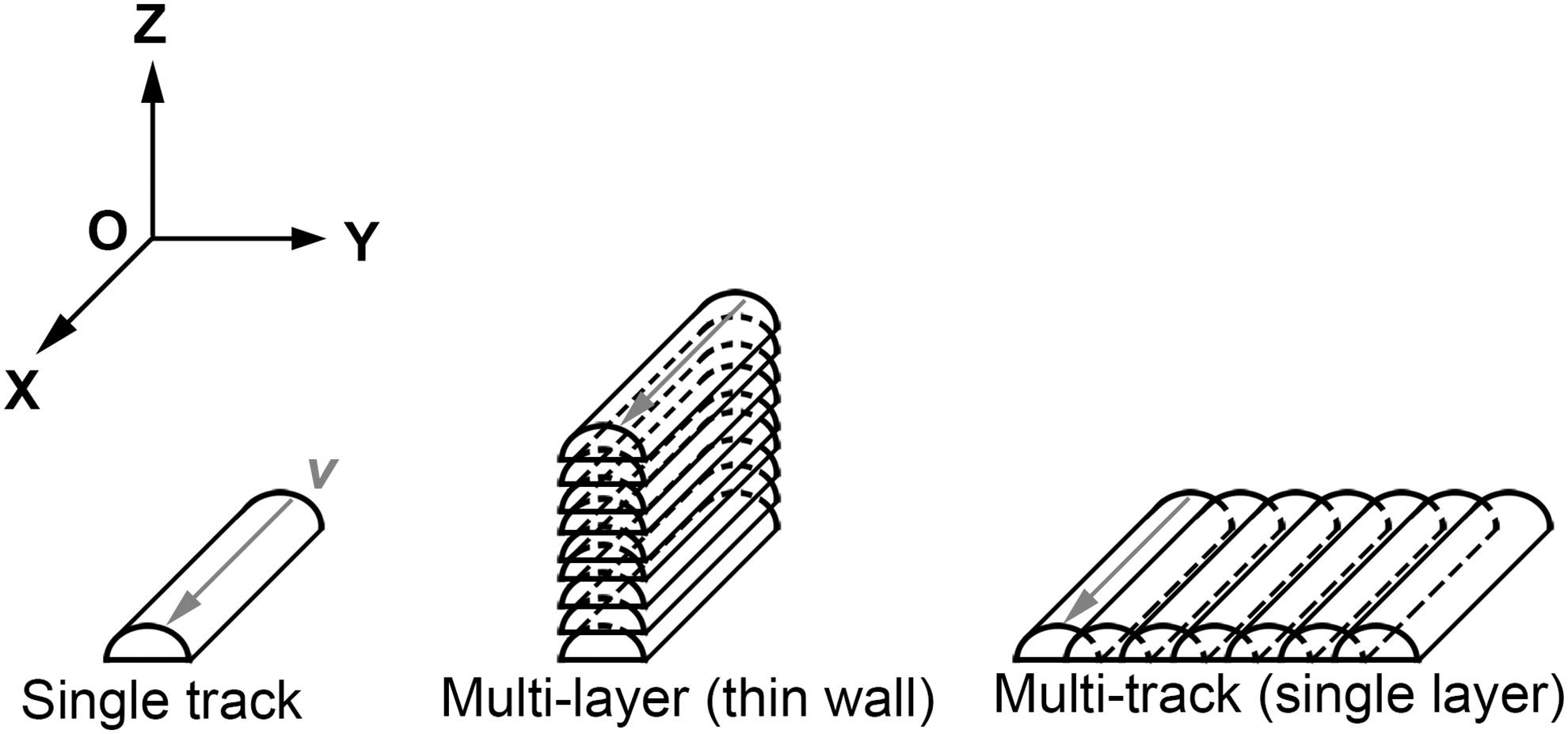
Schematic diagram of coordinate system of LPBF processing and LPBFed samples. LPBF, laser powder bed fusion.
Processing Parameters Used for Thin Wall, Single Layer, and Cubic Samples in LPBFed Al-Cu-Mg-Mn Alloy
LPBF, laser powder bed fusion.
Microstructure characterization
The metallographic procedure of the samples were evaluated by using the method introduced in our previous publication. 15 The morphologies of the LPBFed samples were investigated by Nikon EPIPHOT 300 optical microscope (OM) and the laser scanning confocal microscope (LSCM; KEYENCE VK-X200K). The microstructure of specimens was analyzed through Nikon EPIPHOT 300 OM, environmental electron microscopy (ESEM; ZEISS EVO18), scanning electron microscopy (SEM; FEI, Nano SEM 450), and electron backscattered diffraction (EBSD; ZEISS Gemini 300). Specimens for EBSD were electropolished in 10% perchlorate ethanol at 0°C for 40 s. During the EBSD measurement, the step size was 1 μm.
Results and Discussion
Effect of vertical thermal cycle on the formation of hot cracking in LPBFed thin wall
Morphology of molten pool
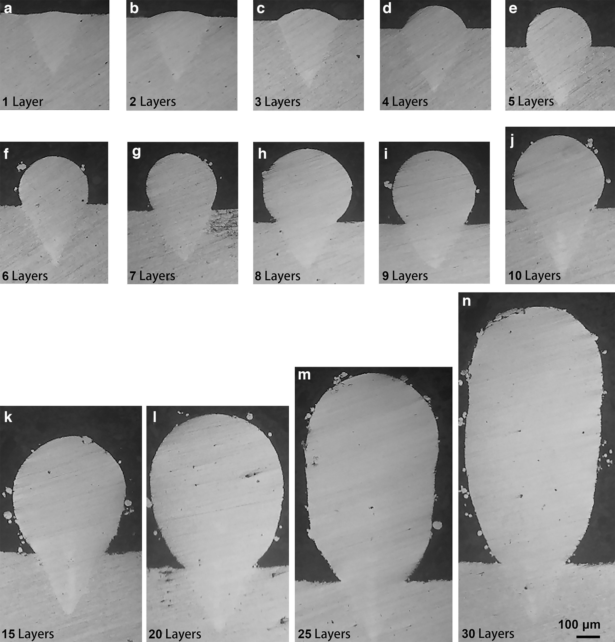
As the number of deposited layers increases, cross-sections of the thin-wall samples fabricated at all scanning speeds show the shape of an “ice cream cone,” that is, the inside of the substrate (the bottom of the molten pool) is conical, and the upper part of the substrate is ellipsoid. In the case of a thin-wall sample fabricated at a scanning speed of 83 mm/s, the curvature radius at the height of the molten pool gradually decreases and forms a complete circle. Then, taking the curvature radius as the width of the thin wall, the growth occurs along the deposited direction and eventually becomes stable, as shown by the red dashed circle in Figure 2. The penetration depth of the molten pool gradually decreases, and the bottom of the molten pool changed from a conical to a bowl shape, as shown by the white dashed lines in Figure 2.
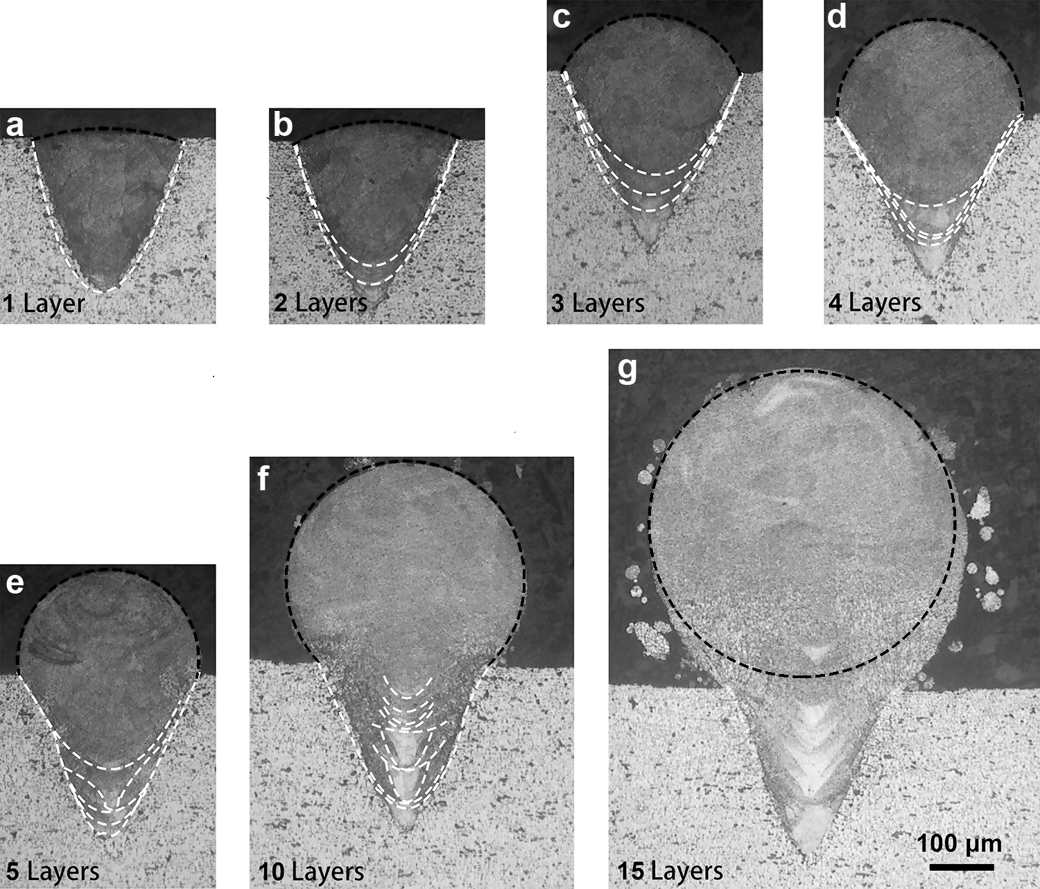
Cross-section of molten pools under various deposited layers at the scanning speed of 83 mm/s:
To study the evolution law of the cross-section morphology of thin walls, the size characteristics of the actual melting height, melting width, curvature radius corresponding to melting height, and typical morphology of half-wall thickness of thin walls under different scanning speeds were statistically analyzed. The measurement schematic is shown in Figure 3, and the measurements for a typical size of thin walls are shown in Figure 4. At different scanning speeds, the melting width and depth first increase, then decrease, and then stabilize as the increase of the number of deposited layers. The actual melting height is always lower than the theoretical melting height, and the curvature radius of melting height decreases gradually at first, then becomes stable after 10 layers, and its size is consistent with the half-wall thickness of thin wall (Fig. 4).
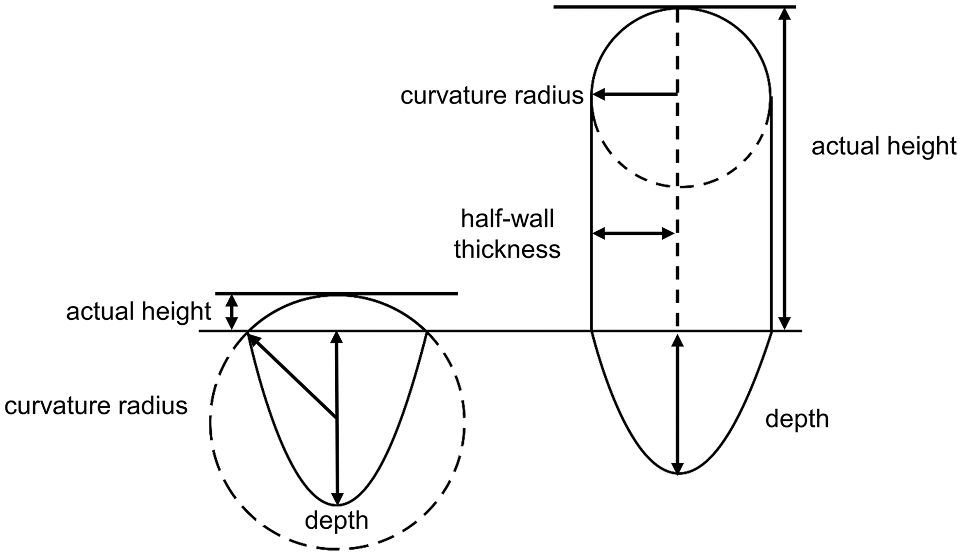
Schematic diagram of typical dimension of thin walls.
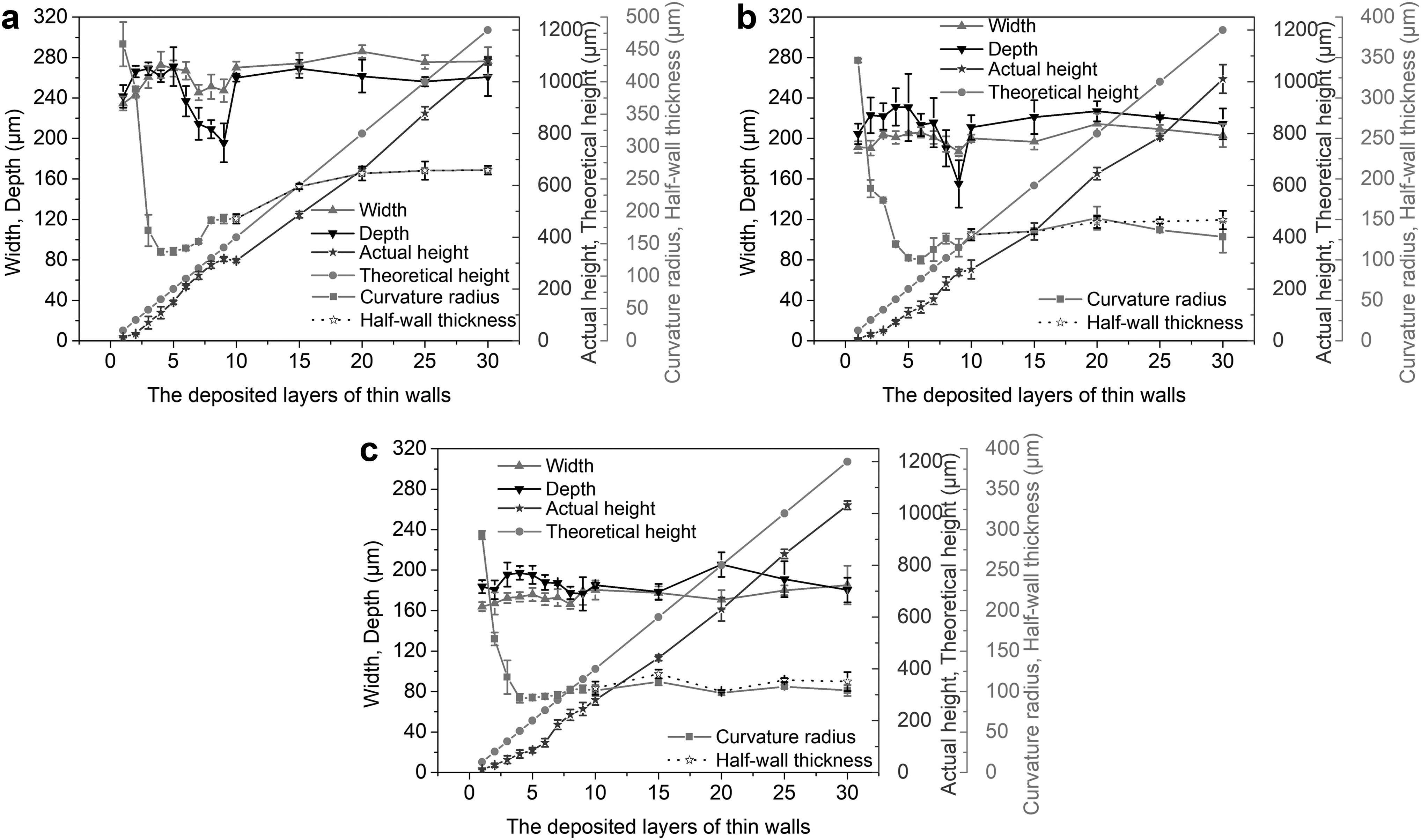
Measurement statistics of typical dimension of thin walls fabricated at different scanning speeds:
Initation and propagation of hot cracking
When the scanning speed is 83 mm/s, no cracks exist in the cross-section of the melt track under different layers (Fig. 5). When the single track with hot cracking is selected to form the thin-wall samples, the solidification cracks gradually become smaller and shallower, the cracks in the molten pool center (MPC) heal, and the cracks at the molten pool boundary (MPB) reduce with the increase in the number of deposited layers (Fig. 6). At a scanning speed of 333 mm/s, thin wall deposited layers of 1–6 layers, the cracks propagate from substrate along the grain boundary of epitaxial growth grains, with the increase in the number of deposited layers, the inside of the molten pool solidification cracks throughout the long and deep cracks of molten pool gradually transforming into short and shallow cracks presents an indistinct dotted break, and distribution in the thin wall edge, as shown in arrows in Figure 6a–e. When the scanning speed is 500 mm/s, the solidification cracks at MPB decreases with the increase in the number of deposited layers, but the cracks in MPC of the thin wall basically disappears, and the change trend of the crack is similar to that when the scanning speed is 333 mm/s (Fig. 7).
Cross-sections of thin-wall samples with different layers (1–30 layers) fabricated at 83 mm/s:
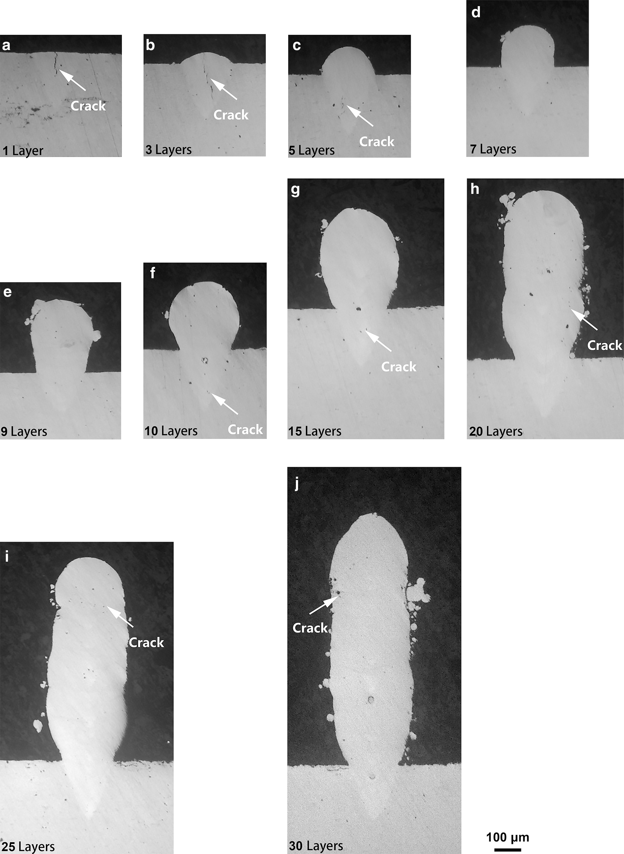
Cross-sections of thin-wall samples with different layers (1–30 layers) fabricated at 333 mm/s:
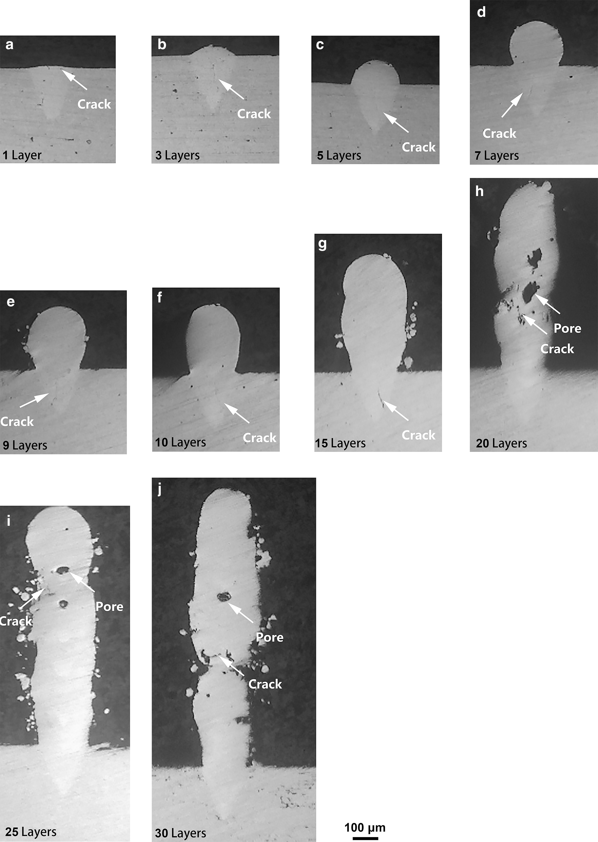
Cross-sections of thin-wall samples with different layers (1–30 layers) fabricated at 500 mm/s:
However, the cracks at the edge of the thin wall are reduced. In addition, when the scanning speed is 500 mm/s and the number of deposited layers reaches 20, the stability of tracks decreases, and a large number of unfused interlayer pores appear (Fig. 7h–j), and cracks appear near due to the formation of unfused pores. The formation of unfused pores is closely related to the balling phenomenon (poor surface quality). When the scanning speed is too high, the energy input is low, the molten pool exists for a short time, and the liquid phase cannot be fully spread.
Microstructure of molten pool
In the thin wall deposition, the microstructure changes with the increase of deposited layers. Figure 8 exhibits the grain morphology of thin walls with different deposited layers. The morphology of molten pool under the substrate (depth) of all thin-wall samples is basically the same: the MPB exhibits epitaxial growth perpendicular to the MPB and along the opposite direction of heat dissipation, and the center line of molten pool exhibits fine equiaxed grains, the formation reason of which has been described in the single-track microstructure in our previous work. 15 With the increase in the number of deposited layers, the grain morphology of molten pool above the substrate (height) changes, resulting in two kinds of grain morphology in the molten pool at the molten height zone: the thin columnar grains growing along the deposition direction in the middle and the fine equiaxed grains at the top. With the increase of the layer number of deposition, the direction of maximum heat dissipation changes from perpendicular to the MPB in the depth region to downward along the deposition direction (Fig. 9), the equiaxed grains at the top of previous layer under the action of vertical thermal cycle, resulting in remelting and resolidification.
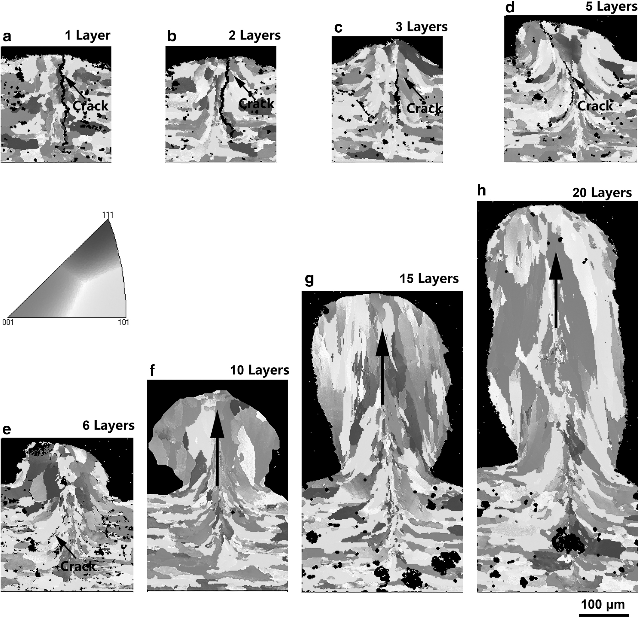
EBSD results of thin-wall samples with 1–20 layers fabricated at 333 mm/s:
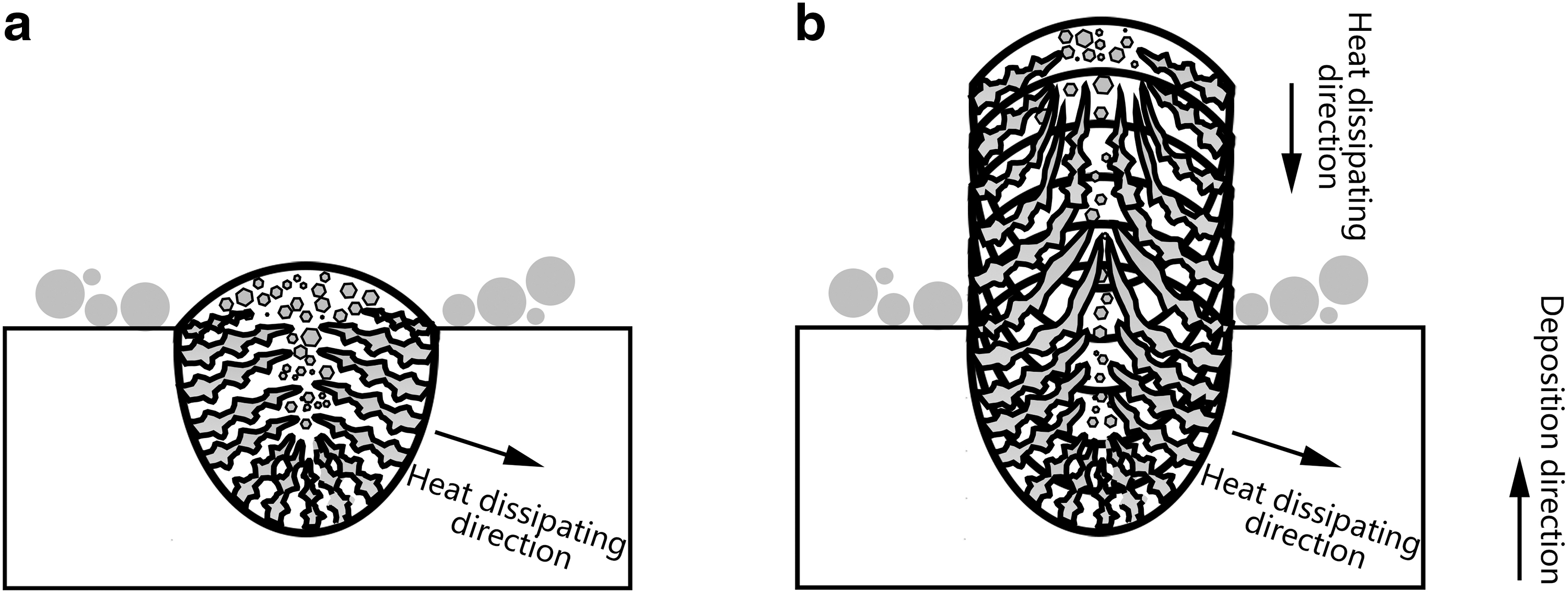
Schematic diagram of microstructure transformation during thin wall depositing:
Inevitably, elongated narrow columnar grains growing along the deposition direction are formed in the middle of the melt height zone, as indicated by the arrows in Figure 8f–h. When the last layer is deposited, the thermal gradient at the top of the molten pool is small and the solidification rate is fast, leading to the formation of fine equiaxed grains (columnar equiaxed transition, CET).
Figure 10 shows the SEM images of different deposition areas of thin walls with 10 layers fabricated at a scanning speed of 333 mm/s. In the center line of molten pool, from the bottom to the top of the molten pool, the dendrite morphology and spacing have changed. At the bottom of the molten pool, as revealed in Figure 10b, the spacing of columnar dendrites is relatively large, which is because the cooling rate at the bottom of the molten pool is low and the columnar dendrites are coarser. As the number of deposition layers increased, the cooling rate gradually increased, the columnar dendrites were refined, and the spacing decreased, as shown in Figure 10c. At the top of the molten pool, the thermal gradient (G) is small and the solidification rate (vs) is large. Since the value of G/vs exceeds the critical value of columnar dendrite to equiaxed dendrite (Fig. 11), the microstructure is further refined from columnar dendrite to equiaxed dendrite, as shown in Figure 10d. In addition, the growth direction and morphology of dendrites on the right boundary of the molten pool also change. The boundary of the molten depth zone is columnar dendrites growing perpendicular to the boundary (Fig. 10e), and the boundary of the molten height zone is cellular dendrites (Fig. 10f).
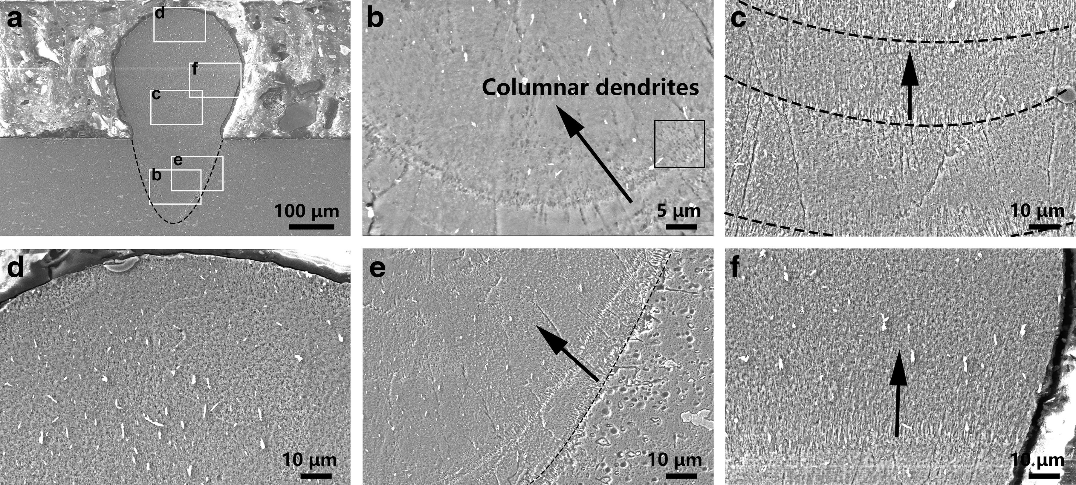
SEM images showing the different zone of thin wall sample with 10 Layers fabricated at v = 333 mm/s:
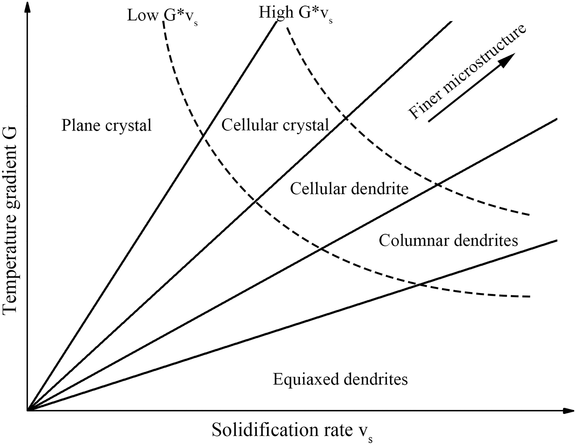
Effect of temperature gradient G and solidification rate vs on the morphology and size of solidification microstructure.
This is caused by the different heat dissipation conditions in the two zones. The melting depth area is only in direct contact with the substrate, while the melting height zone is in contact with the deposited solid metal below, and the metal powder is in contact with the right side. The thermal conductivity of the metal solid is much higher than that of the metal powder, so the heat dissipation is mainly to the metal solid zone, which changes the dendrite growth direction. Due to the preheating effect of heat accumulation, the G, of the molten height zone is smaller than the molten depth zone. For the vs, the molten height zone is larger than the molten depth zone. Therefore, for G/vs, the molten height zone is smaller than the molten depth zone, so that the dendrite morphology changes transform columnar dendrite to cellular dendrite.
Formation mechanism of hot cracking in thin-wall samples
The temperature field changes as the number of deposited layers increases. The deposited layer has a preheating effect on the latter layer, and the latter layer has a slow cooling effect on the deposited layer. In addition, the increased number of deposited layers will also bring a change in the stress field in the LPBF processing, and the deposited layer have a preheating effect on the last layer, which can reduce the internal stress. The next laser scanning will remelt the deposited layer, leading to the reduction of internal stress when it is completely melted into a liquid phase. At the same time, the increase in the number of deposited layers also leads to the evolution of microstructure, forming fine grains and inhibiting the generation of solidification cracks. Since the melting depth of the single track is about 200 μm, much larger than the thickness of the powder layer (40 μm), most of the molten pool with deposited layer and solidified in the vertical direction is remelted by the latter layer, as shown in Figure 12b. The crack in the MPC is called the central solidification crack, and the crack in the MPB is called the edge solidification crack, as shown in Figure 12a.
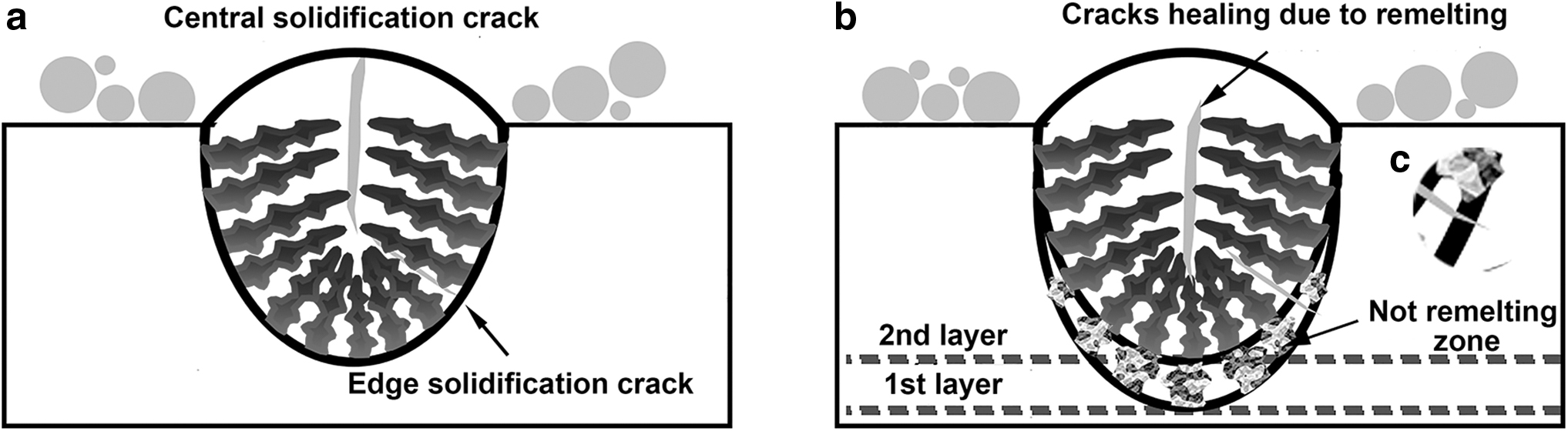
Schematic diagram of crack evolution under vertical thermal cycle:
Applying vertical thermal cycle of LPBF processing, solidification crack has produced center (Fig. 12a) green area melting, the second-layer spread powder after laser melting will provide additional liquid, and under the action of gravity to fill, adequate amount of liquid phase is beneficial to promote the healing of MPC before solidification crack in orange (Fig. 12b). In addition, remelting brings about the solidified dendrite fracture, which acts as a nucleating particle, refines the grains in the center of the molten pool, and inhibits the generation of cracks. For the solidification crack at the MPB, the second-layer remelting will not completely cover the crack, resulting in the crack source still existing, as shown in the green area in Figure 12c. However, the crack at the MPB is reduced due to the preheating and slow cooling rate. For the top of the thin wall, almost no solidification cracks occur, because after multilayer deposition, the preheating effect of the deposited layer is significant, which is helpful to reduce the G in the solidification processing; the CET occurs, and the formation of fine equiaxed grains inhibits the generation of cracks.
With the increase of melt temperature and melt fluidity, the dendrite gap is filled by liquid reflux to promote the crack healing. The higher the scanning speed, the smaller the remelting area and the weaker the healing effect on the edge cracks of the molten pool. Therefore, the application of vertical thermal cycling can help to heal the solidification cracks in the center of the thin-wall molten pool and reduce the solidification cracks at the edges.
Effect of horizontal thermal cycle on the formation of hot cracking in LPBFed single layer
Effect of the number of scanning tracks on hot cracking
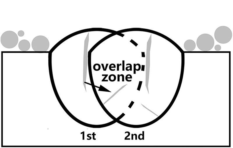
The single-layer samples with scanning spacing of 0.09 mm and scanning speed of 167 mm/s were selected to analyze the effect of scanning track number on the formation of hot cracking. On the cross-section of the single-layer sample, the location diagram of the overlap zone between tracks is shown in Figure 13. The red area in Figure 13b is the overlap zone. Figure 14 shows SEM images of the cross-section of the single-layer smaples. When the number of scanning tracks is 2 or 4, no cracks are found in the cross-section. It can be seen that when the number of scanning tracks is less than or equal to 4, the processing parameters of a single track without cracks still have no cracks. When the number of scanning tracks is 5, in addition to the crack found in the fifth track, the crack also appears in the fourth track close to the edge of the fifth track, as shown in Figure 14c and d with its local magnifications. When the number of scanning tracks was 9, cracks were also observed in fifth and ninth tracks (Fig. 14e, f), and the locations of cracks were randomly distributed.

The schematic diagram of cross-section comparision of different samples:
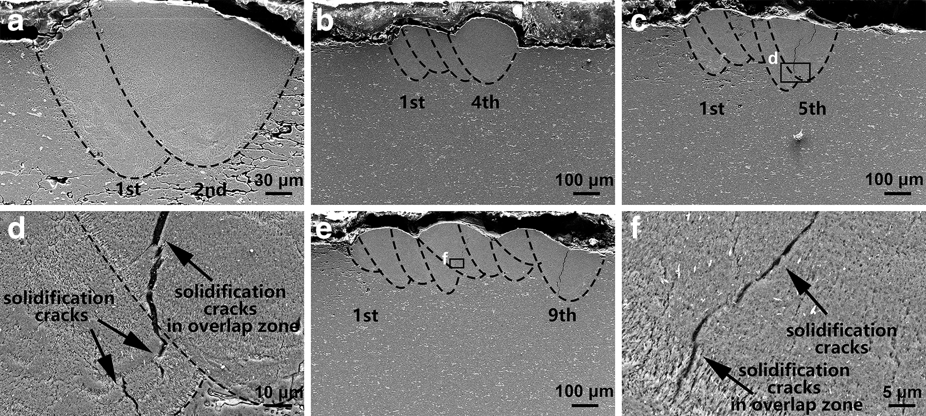
SEM images of single-layer sample fabricated at v = 167 mm/s and h = 0.09 mm:
Figure 15b is a local enlarged view of the crack in the single-layer sample with scanning speed of 333 mm/s. Dendrites can be seen in the crack, as shown by arrows in Figure 15b, which proves that the crack in the sample is a solidification crack related to the liquid film.
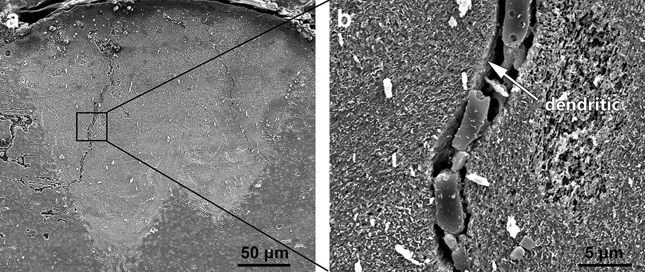
SEM images of single layer with two tracks fabricated at v = 333 mm/s and h = 0.09 mm:
Therefore, under the action of horizontal thermal cycling, cracks can be divided into edge, center, and overlap zone cracks according to the initiation of the hot cracking, as shown in Figure 16. The formation mechanism of the edge and center crack of the molten pool has been described, so it will not be repeated.
Schematic diagram of the initiation position of hot cracking.
According to the initiation of and the propagation direction of the hot cracking, the relationship among the number of scanning tracks, scanning speeds, and initiation position were statistically analyzed. In the samples with cracks, there is no obvious bias in the initiation position of cracks, and the proportion of cracks in the three zones (center, boundary, and overlap zone) is equal. The single-layer samples are crack free at the scanning speed of 83 mm/s. When the scanning speed is increased to 167 mm/s, hot cracking occurrs after the number of scanning tracks reached 4. As a scanning speed of 250 mm/s, hot cracking initiation in the overlap zone occurs when the number of scanning tracks is only 2. When the scanning speed is 333 mm/s, the crack exists. With the increase of the scanning speed, the threshold of the number of tracks gradually decreases. This is because when the scanning speed is low, the MPC temperature is high, the molten pool exists for a long time, the liquid phase amount is enough, and the preheating effect of the deposited track is stronger, which makes the thermal gradient in the overlap zone relatively low, thus delaying the occurence of hot cracking in the overlap zone.
The crack in the overlap zone can be divided into two types based on the initiation position, one originating in the nonoverlap zone and the other in the overlap zone. The crack originating in the nonoverlap zone grows along the boundary of columnar grains in the overlap zone and extends to the overlap zone, which is consistent with the formation mechanism of other solidified cracks in the nonoverlap zone and will not be described here. The second type of crack originating in the overlap zone can be explained by Figure 18. The overlap zone refers to the remelting of some areas of the solidified fusion track. On the other hand, in the overlap zone, the laser directly acts on the solid metal, and the absorption rate of the solid metal to the laser is much lower than that of the metal powder, and the heat dissipation effect is strengthened, leading to the increase of the thermal gradient in the overlap zone, and the increase of nonequilibrium solidification and solidification shrinkage stress, 47 thus increasing the hot cracking sensitivity. The solidification crack appears in the single track where the processing parameters can form dense without crack.

The relationship among the number of scanning tracks, scanning speed, and initiation position of hot cracking.
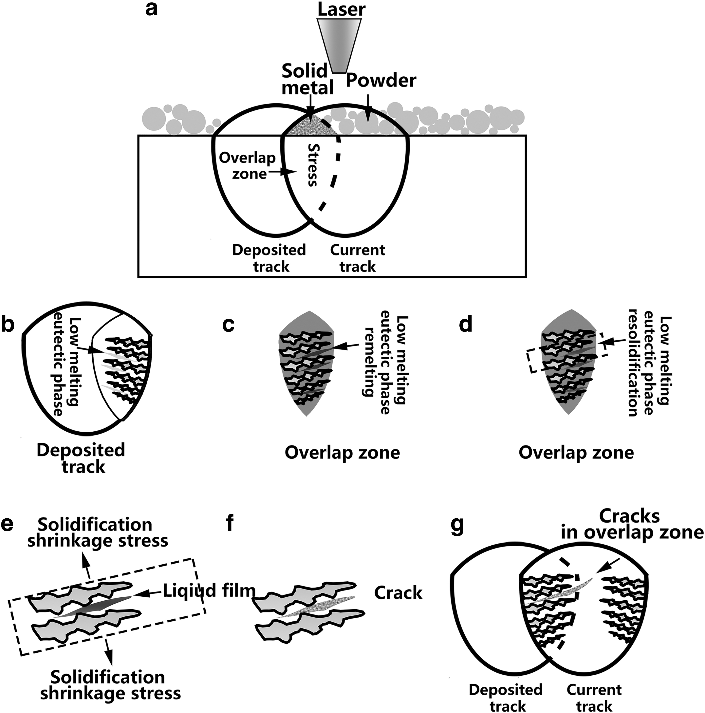
Detailed formation mechanism diagram of hot cracking originated in overlap zone:
The horizontal thermal cycling of LPBF will increase the tendency of hot cracking and lead to the hot cracking in the overlap zone.
Effect of hatching space on hot cracking
Single-layer samples with five tracks fabricated at v = 167 and 500 mm/s were selected to analyze the influence of hatching space on the hot cracking, and the metallographic diagram is shown in Figure 19. The single track under v = 167 mm/s is crack free. When the hatching space is 0.15 mm, hot cracking occurs in the third track (Fig. 19d). When the hatching space is 0.12 mm, hot cracking occurs in the fourth track (Fig. 19c). When the hatching space decreases to 0.09 mm, hot cracking occurs in the fifth track (Fig. 19b). When the hatching space of 0.06 mm is adopted, there were no cracks in the all tracks (Fig. 19a). It can be seen that when the scanning speed is 167 mm/s, the critical number of track of hot cracking initiation decreases with the increase of hatching space. In addition, the hot cracking is in the overlap zone and center of the molten pool as shown by arrows in Figure 19b–d. There were cracks in the single weld with a scanning speed of 500 mm/s, and cracks in all the samples with five single-layer channels, but there were fewer cracks in the sample with a hatching space of 0.06 mm, as shown in Figure 19e. The small hatching space of 0.06 mm has a certain effect on the formation of cracks.
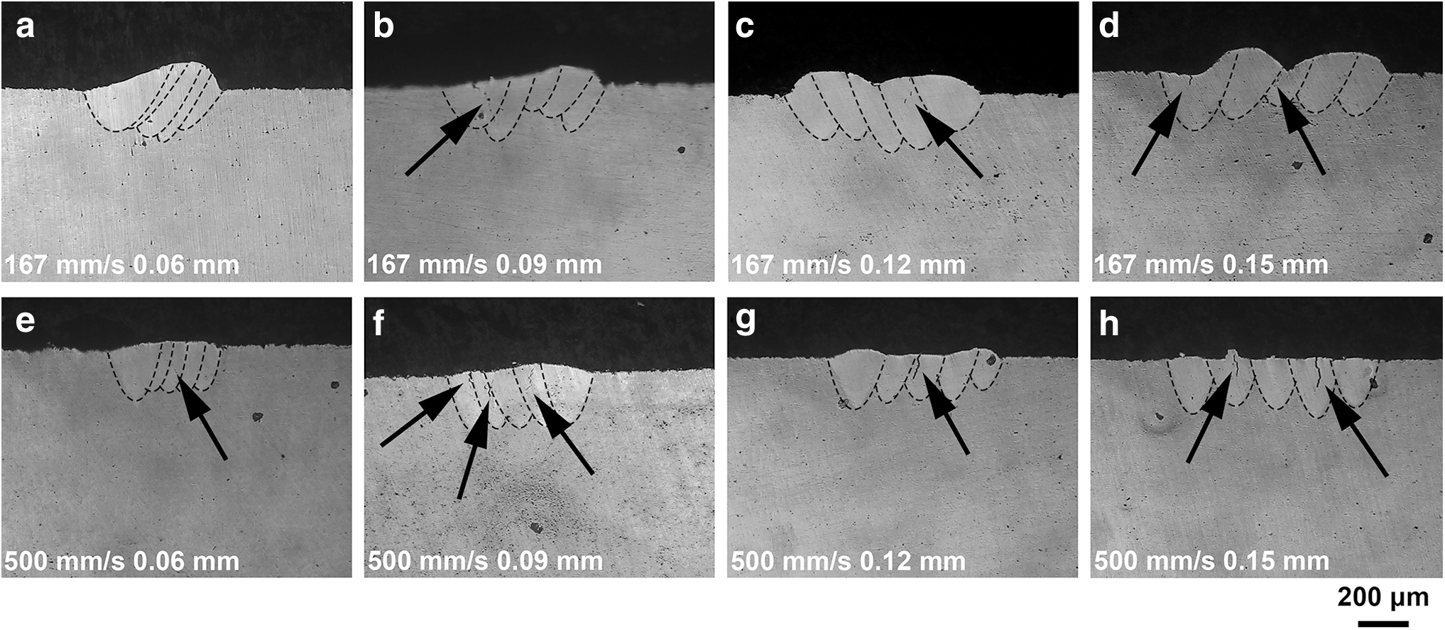
The optical micrograph of the single layer with five tracks fabricated at different scanning speeds:
Effect of complex thermal cycle on the propagation of hot cracking
The comparison of microstructure under different thermal cycles
Under the effect of a single horizontal thermal cycle, the bottom of the molten pool is columnar grains with epitaxial growth, and the inner part of the molten pool is a coarse equiaxed grains, as shown in Figure 20a. Under the effect of a single vertical thermal cycle, the center line of the molten pool is a mixture of elongated columnar grains growing along the deposition direction and fine equiaxed grains between layers, while the boundary of the molten pool is a coarse columnar grain growing epitaxial perpendicular to the boundary of the molten pool, and the top of the molten pool is a fine equiaxed grain, as shown in Figure 20b. Microstructure under complex thermal cycling is shown in Figure 20c. It can be seen that the microstructure under the complex thermal cycle as a whole presents columnar grains growing along the opposite direction of heat flow. Since the rotation angle of interlayer scanning is 90°, the direction of heat flow is no longer along the deposition direction, but has a certain angle deflection. In addition, there are still a few fine equiaxed crystals between the layers.

Microstructure of sample under different thermal cycling:
In cubic samples, a single layer is formed under horizontal thermal cycling, and its microstructure is coarse equiaxed grains. Then a vertical heat cycle is applied after rotation of 90°. The coarse equiaxed grains grow epitaxial along the opposite direction of heat flow, gradually increasing the length:diameter ratio of grains and forming columnar grains. In addition, under the action of vertical thermal cycle, because the melting depth of the molten pool is greater than the thickness of the powder layer, it will remelt the solidified metal, resulting in dendrite fusion of some columnar dendrites, and free dendrite fragments acting as nucleating particles, thus forming a small number of fine equiaxed grains between the layers. Finally, the cubic samples present microstructure of columnar grains mixed with fine interlayer equiaxed grains, which is similar to the microstructure of a single vertical thermal cycle sample.
With the increase of scanning speed, the increase of cooling speed is small, which does not make the grain size change obvious, but the deflection angle of interlayer grain growth changes from right angle (Fig. 21a) to acute angle (Fig. 21c). Due to the thermal gradient and cooling rate increase with the increase of the scanning speed, the grain growth direction too late to change, tend to maintain the original direction of growth, and rotation angle has little influence on it. With the increase of scanning speed, the change of heat flow direction becomes smaller, making the crack length longer and penetrating through the multilayer.
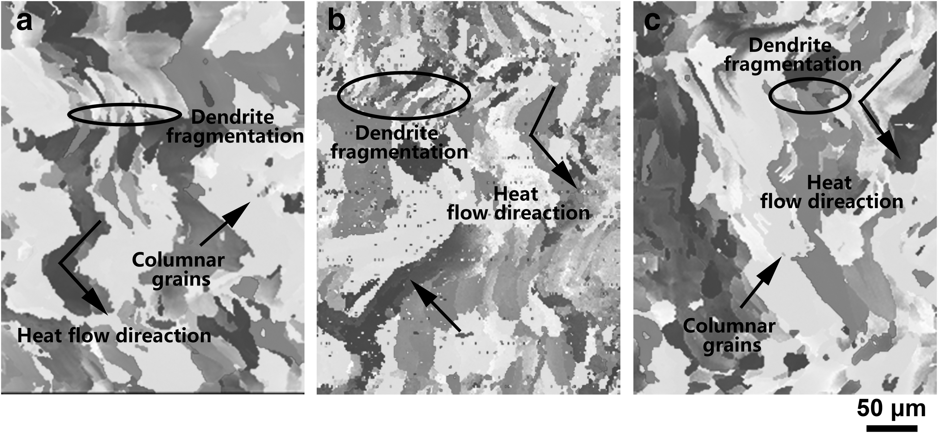
EBSD images of cross-section of samples with different scanning speeds:
Formation mechanism of hot cracking in cubic samples
Figure 22 shows the cross-section OM images of samples at different scanning speeds. The types and quantities of defects increase with the increase of scanning speed. When the scanning speed was 167 mm/s, a small number of unfused pores (at the arrow of Fig. 22b) and cracks along the deposition direction (at the circle of Fig. 22b) began to appear. When the scanning speed reaches 250 mm/s, cracks appear in the unfused pores.
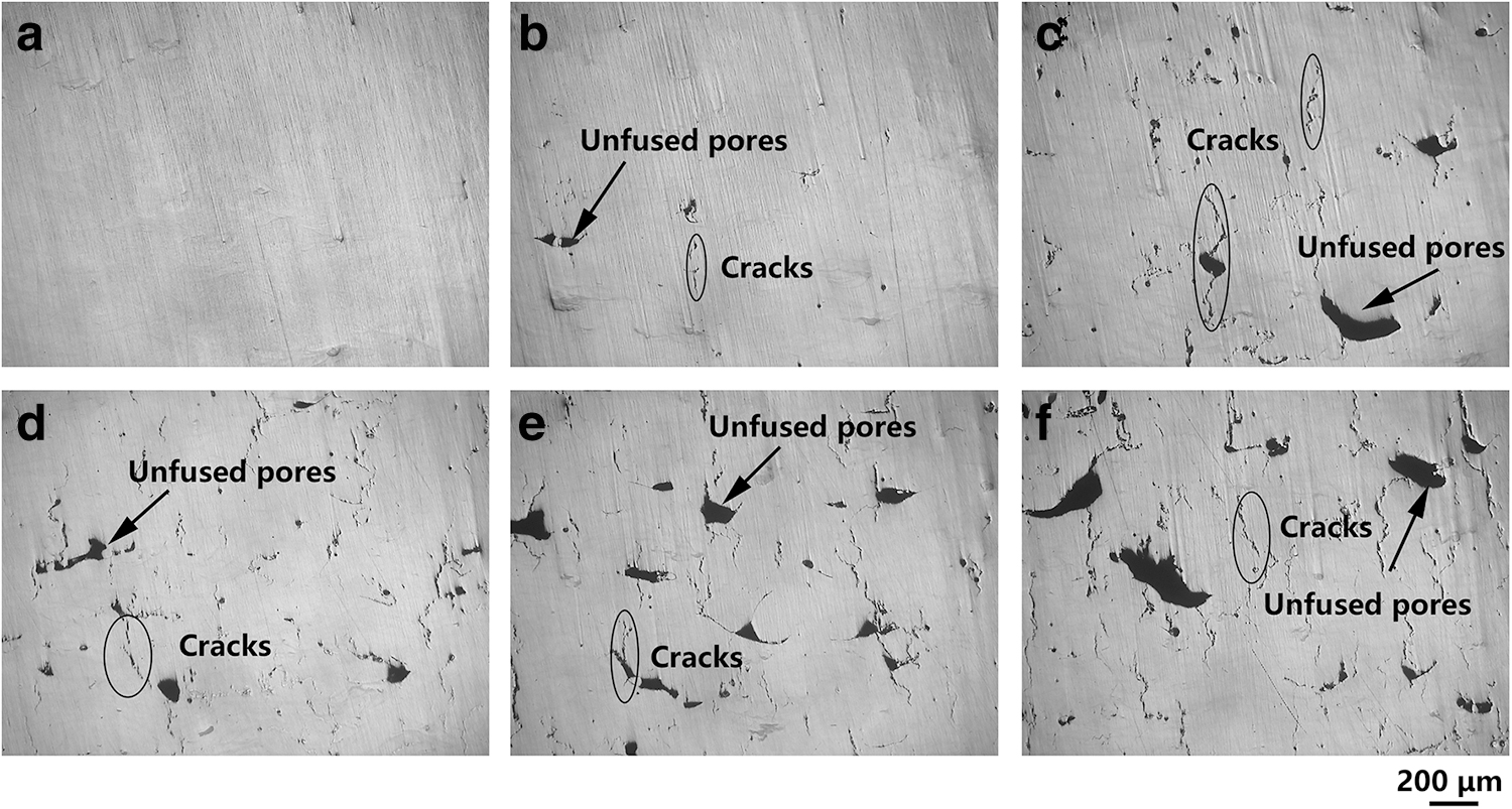
The metallograph of cross-section of the samples fabricated at different scanning speeds:
Under the action of complex thermal cycle, new cracks are caused by unfused pores. There are no unfused pores in the samples during the single-track and single-layer samples. The unfused pores appear in the samples of thin wall with high scanning speed. Therefore, the formation of unfused pores is closely related to the surface quality and scanning speed of the sample. When the scanning speed is too high, the energy input is low, the molten pool exists for a short time, and the liquid phase cannot be fully spread, forming a rough and uneven surface under the action of horizontal thermal cycling. Then, the rough surface results in uneven powder thickness when the next layer is applied. After the vertical thermal cycle is applied, when the laser acts on the thin powder layer, the energy input is high and the thermal gradient is high, which leads to the strong Marangoni convection and spheroidization phenomenon. When the laser acts on the thick powder layer, the energy input is low and it is difficult to melt the powder completely, resulting in the formation of unfused pores. Under the genetic effect of vertical thermal cycle layer on layer, unfused pores are difficult to heal and eliminate.
Unfused pores show irregular shapes and stress concentration exists at their sharp corners. The larger the size of the pore, the more irregular the shape, especially when there is a sharp angle, the greater the stress intensity factor. Therefore, the unfused pore becomes the initiation point of the crack and grows along the boundary of the columnar grain. Furthermore, above the solidus temperature, cavities and pores are prone to form in the semisolid zone and can provide initiation sites for insipient cracks.48,49 During melting, powder surface oxide reacts with melt and forms local Al2O3 inclusions, which results in poor melt wettability during LPBF. The schematic diagram of the crack growth at the unfused pore is shown in Figure 23. In addition, with the increase of scanning speed, the liquid phase reflux is insufficient, and the low-melting point eutectic phase forms a thin liquid film, which forms cracks under the action of high strain rate. Therefore, under the action of complex thermal cycling, cracks are generated not only at the boundary of columnar grains, but also at the unfused pores.
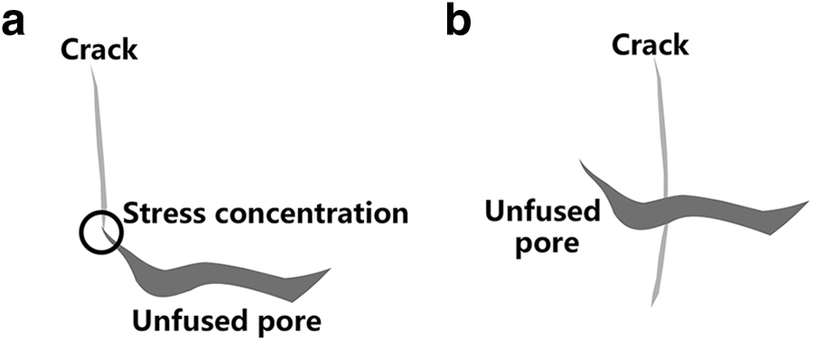
Diagram of cracks at unfused pores:
Conclusions
In this work, the fusion morphology evolution and hot cracking formation mechanism of high-strength Al-Cu-Mg-Mn alloy fabricated by LPBF with different processing parameters, such as thin-wall samples under vertical thermal cycling, single-layer samples under horizontal thermal cycling and cubic samples under complex thermal cycling are studied, which are of great significance to guiding the processing optimization. The main results of the study are summarized as follows:
Under vertical thermal cycling, the crack sensitivity is weakened, the cracks in MPC is inhibited, and the cracks at MPB is reduced. The increase of the number of layers provides the effect of preheating and slow cooling, prolonging the lifetime of molten pool and liquid phase, and reducing the residual tensile stress, resulting in the decrease of crack sensitivity. With the increase of the number of deposited layers, the microstructure of the molten pool in the molten height zone is transformed into small columnar dendrites, which is conducive to the filling and reflux of liquid phase to promote the healing of the molten pool central crack and inhibit the generation of crack. Therefore, vertical thermal cycling was applied to promote the healing of the solidification crack in the center of the molten pool and reduce the solidification crack at the boundary of the molten pool. Under the horizontal thermal cycling, the crack sensitivity increases, leading to the crack in the overlap zone. With the increase of the number of scanning tracks, the horizontal remelting and overlap bonding are introduced. On the one hand, the grain size of the overlap zone is coarse, and the ability to resist the solidification shrinkage stress decreases. On the other hand, in the overlap zone, the direct interaction between laser and solid metal leads to the increase of thermal gradient in the overlap zone, resulting in the increase of stress and thus the increase of crack sensitivity. With the increase of the scanning speed, the threshold of tracks without cracks decreases gradually. When other processing parameters are fixed, the crack-free zone decreases with the increase of hatching space. Under the complex thermal cycle, in addition to the solidification cracks along the boundary of the columnar grains, the cracks caused by the unfused pores are also formed. With the increase of scanning speed, the unfused pores increase. Under the action of single vertical thermal cycling, the solidification cracks at the center of the molten pool will heal, while the solidification cracks at the boundary of the molten pool will decrease. Under the action of single horizontal thermal cycling, the initiation point and propagation path of solidification crack are formed at the overlap of molten pool. Under the alternating action of horizontal and vertical thermal cycles, the solidification cracks do not disappear, but always exist. Under the action of single vertical thermal cycling, the solidification crack in MPC will heal, but the solidification crack at MPB still exists. Under the action of single horizontal thermal cycling, the initiation point and propagation path of solidification crack are formed at the lap of molten pool. However, under the alternating action of horizontal and vertical thermal cycles, the crack would not disappear, but would always exist and propagate through the multilayer. The crack was still intergranular cracking and the liquid film and dendrite processes remained inside the crack. The hot cracking in LPBFed Al-Cu-Mg-Mn alloy is expected to be solved by surface remelting, layer-by-layer remelting, short scanning length, low scanning speed and other strategies, which could provide preheating, long lifetime of molten pool and reduce the stress.
Footnotes
Authors' Contributions
X.N.: microstructural analysis, methodology, and writing—original draft. F.P.: writing—review and editing. Z.H.: microstructural analysis, methodology, and writing—review and editing. Y.Q.: investigation and microstructural analysis. Ha.Z. and Hu Z.: writing—review and editing.
Author Dislosure Statement
The authors declare that they have no known competitive economic interests or personal relationships that could affect the work reported in this article.
Funding Information
This work was sponsored by the self research and development plan of the Naval University of Engineering (No. 2022505010) and the project (Grant No. 6230113009). The authors would like to thank the Analytical and Testing Center of HUST for EBSD measurement.