




Abstract
Fused-filament fabrication (FFF) is an extremely popular additive manufacturing process due to its affordability, relative ease to operate, and wide range of possible materials. It is also notorious for the hundreds of different process variables, which often are overlooked in favor of parameters considered to be more relevant for mechanical performance, such as printing and bed temperatures, printing speed, and layer height. Thus, this study is aimed at evaluating some of the less frequently studied process variables, namely raster orientation angles (and their stacking sequence) and feeding rate. Based on this, the influence of these variables on the tensile and flexural properties of short carbon fiber-reinforced polyamide printed by FFF was assessed. The study concluded that stacking layers with raster angles of 0°/90° and +30°/−30° resulted in the best trade-off between tensile and bending properties, with the former reaching ultimate tensile and flexural strengths of 111 ± 1 and 137 ± 5 MPa, respectively. The study also found that there was no increase in part density or mechanical properties when the volumetric flow was increased up to 120% of the intended road volume. Therefore, the hypothesis that an increase in flow rate would result in less inter-road gaps could not be confirmed with the current setup.
Introduction
It is well known that the mechanical properties of components 3D printed by fused-filament fabrication (FFF) can be highly influenced by the main process parameters, which normally include the printing and bed temperatures, printing speed, and layer height.1–8 There are, however, many other process variables that can easily become obscured and overlooked, for example, number of contours, infill pattern, print head acceleration and fan speed, and settings for top and bottom layers. To put it in perspective, one of the most well-known slicing software, Ultimaker Cura version 5.3.1 (Utrecht, The Netherlands), lists a total of 620 modifiable variables, with Slic3r v1.3.0 (a popular open slicer developed by a team led by A. Ranellucci) offering >150 modifiable variables.
Many other variables are related to the hardware itself, such as nozzle diameter, chamber/bed size, bed material (as well as the possible use of glues and tapes), among others. Consequently, although this vast collection of parameters opens up many possibilities, it also leaves many aspects of FFF unexplored.
Two of these less explored FFF variables are the raster orientation (or stacking sequence thereof) and the feeding rate. Raster orientation represents the orientation of the infill lines with respect to the length of the part, with different orientations stacked together being possible. Feeding rate represents the amount of material that is fed to the print head per unit of time; in many modern slicing software, this variable is typically managed through a setting referred to as “volumetric flow,” which is expressed as a percentage of the extruded volume needed and calculated based on other input parameters.
The influence of both on the mechanical properties of 3D-printed parts has been explored by other authors9–14 ; however, it is important to mention that most studies focused on commodities such as polylactic acid and acrylonitrile butadiene styrene, with little information on short carbon fiber-reinforced thermoplastics concerning these two variables. Processing these materials through FFF can often be more complex, and as a result, they could greatly benefit from additional experimental data involving these two process variables, especially considering the relevance of these materials.
Short carbon fiber-reinforced thermoplastics provide a valuable balance between processability and strength: they are typically easier to process than long15–17 and continuous18–20 fiber-reinforced polymers, while exhibiting superior mechanical properties when compared with unreinforced matrices. 21
Therefore, this article aims to evaluate the influence of these two FFF parameters on the tensile and flexural properties of FFF-printed parts made from a short carbon fiber-reinforced polyamide (PA). Specifically, the effect of different layer stacking sequences (0°/90°, +30°/−30°, and others) and feeding rates (as represented by the “volumetric flow” setting, ranging from 90% to 120% of the available road volume) was investigated. By evaluating these parameters, it is intended to provide valuable insights into the behavior and optimization of the FFF, especially for short carbon fiber-reinforced thermoplastic polymers such as PA.
The results of this study could have significant implications for the design and optimization of FFF-printed parts, as well as for the development of new materials and printing technologies. By understanding the influence of these often overlooked parameters on the mechanical properties of printed parts, more reliable and effective parameter settings can be developed.
Materials and Methods
Filament material
The specimens were 3D printed using a BASF Ultrafuse PAHT CF15 filament (Emmen, The Netherlands), consisting of a commercial-grade PA matrix reinforced with 6.5 ± 0.2% short carbon fibers, as reported by Belei et al. 1 The diameter of the filament was 2.85 mm, with the average fiber length measured at 136.2 ± 83.0 μm by Belei et al. 22 The filament had a glass transition temperature of 70°C and a melting temperature of 234°C, as per supplier's specifications. 23 During printing, the filament was stored in a heated enclosed box with silica gel to minimize moisture absorption. Water content was not measured in this study as the filament was evaluated in its as-delivered condition.
3D printing
An Ultimaker S5 3D printer was used for the FFF process. Printing was performed on a 4.0-mm thick glass plate without the use of tapes or adhesives. A 0.6 mm diameter printing nozzle was used with a ruby cone to prevent premature wear from the filament's abrasive nature.
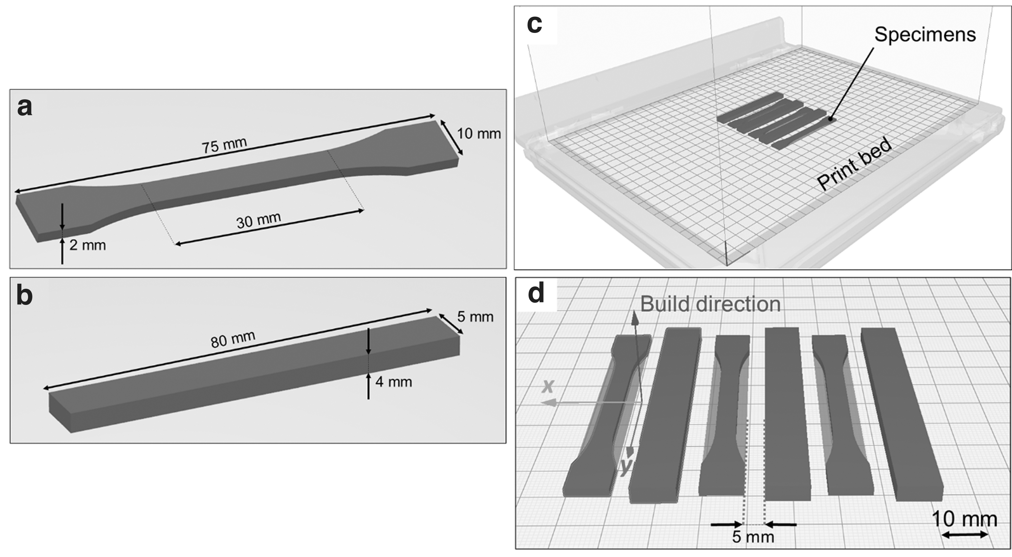
Printed samples for tensile and flexural tests were based on ISO 527:2019 (I-BA) and ISO 178:2019, respectively (Fig. 1). Process parameters used during this study are listed in Table 1. As proposed in the Introduction section, only layer orientation and volumetric flow were varied, with other FFF parameters fixed, based on a detailed design of experiment optimization study published by Belei et al. 1
3D-Printing Parameters Utilized in the Present Study
For convenience, stacking sequences containing more than two different orientation angles were named “Multi 1” and “Multi 2.”
When layer orientation was varied, volumetric flow was set at 100%; when volumetric flow was varied, layer orientation was set at 0°, as to facilitate the density calculation (Estimation of Relative Density Through Image Analysis section). These settings were implemented using the Ultimaker Cura 5.3.1 slicer software. For each unique condition, three tensile specimens and three bending specimens were produced within the same print job (Fig. 1).
Raster orientation angles were identified with respect to the length of the 3D-printed specimens. Specifically, 0° referred to a parallel orientation (y axis; Fig. 1d), whereas 90° referred to a perpendicular orientation relative to the length (x axis). The volumetric flow rate was defined as the proportion of the road volume that was extruded through the nozzle in relation to the volume assigned to each individual road. This factor directly influences the feeding rate, such that at 100%, the amount of material extruded per unit of time matches the volume of the road, as determined by its geometry. A visualization of the volumetric flow on the amount of extruded material is shown in Figure 2.
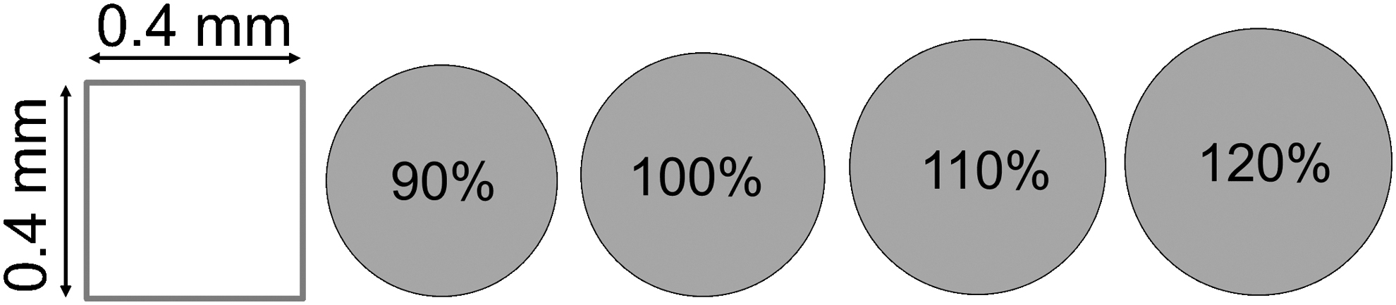
Theoretical representation of single-road cross sections for different flow settings (gray circles) in relation to the available space for the road deposition (red square). At 100%, the road cross section and the available space have the same area.
Mechanical tests
As mentioned previously, two mechanical tests were employed in this study: uniaxial tensile test (ISO 572-1:2019) and a three-point bending test (ISO 178:2019). For both tests, a Shimadzu AGS-X testing rig (Kyoto, Japan) was used, equipped with a load cell of 5 kN. The uniaxial tensile test was carried out with a speed of 2 mm/min. For the three-point bending test, a span length of 64 mm and test speed of 2 mm/min were used. The specimens were placed with their last printed layer facing downward on the lower pins.
Microstructural characterization
Microstructural analysis of specimens was done both with optical and scanning electron microscopy (OM and SEM, respectively). OM was performed with a Zeiss AX10 Observer Z1m microscope (Oberkochen, Germany) in bright field mode. SEM was performed with a Tescan Mira-3 scanning electron microscope (Brno, Czech Republic). Before analysis, specimens were carbon sputtered, and their surfaces were observed using the secondary electron detector at an acceleration voltage of 5 kV, a working distance of 50 mm, and a chamber pressure of 0.1 Pa.
Data analysis
Tensile versus flexural strength trade-off
To rank the different stacking sequences with respect to their mechanical performance, a trade-off between tensile and flexural properties (as measured by the respective mechanical tests) was proposed. In this trade-off, the average tensile and flexural strengths for each stacking sequence condition were normalized using the min–max scaler. This is represented by Eq. (1),
24
where
With this normalization, the best and worst values became 1 and 0, respectively. The normalization was done both for tensile and flexural strengths. On the last step, an average of the normalized values for these two properties was calculated. Conditions were ranked from best to worst based on this average, with higher values representing better performances.
Estimation of relative density through image analysis
For the evaluation of the influence of volumetric flow on the density of 3D-printed parts, the relative density was measured by analyzing cross-sectional OM images from additional tensile specimens (i.e., manufactured specifically for this task) using ImageJ (USA). Pixels representing pores were turned black, whereas other regions were turned white (binary filter) (Fig. 3). The ratio between the area in white and the total image area was considered the specimen relative density. The process was repeated for three different specimens per flow setting. Finally, the weight as a function of the flow setting was assessed by weighing each dog bone tensile specimen before the testing using a Kern EW weight scale (Germany) with an error of ±0.01 g.

Results and Discussion
Layer stacking sequence
An overview of the test results is provided in Figure 4. The 0°/90° stacking sequence reached the highest ultimate tensile strength (UTS) with 111.3 ± 1.0 MPa. Regarding the flexural properties, +30°/−30° resulted in the highest ultimate flexural strength (UFS), 144.6 ± 2.2 MPa. It was possible to conclude that both 0°/90° and +30°/−30° exhibited the best overall performance as a whole, being the two best in both categories while showing also relatively limited scatter. On the opposite end, +60°/−60° showed the worst overall performance. A ranking of the evaluated stacking sequences based on a quantitative trade-off analysis is presented in Table 2.
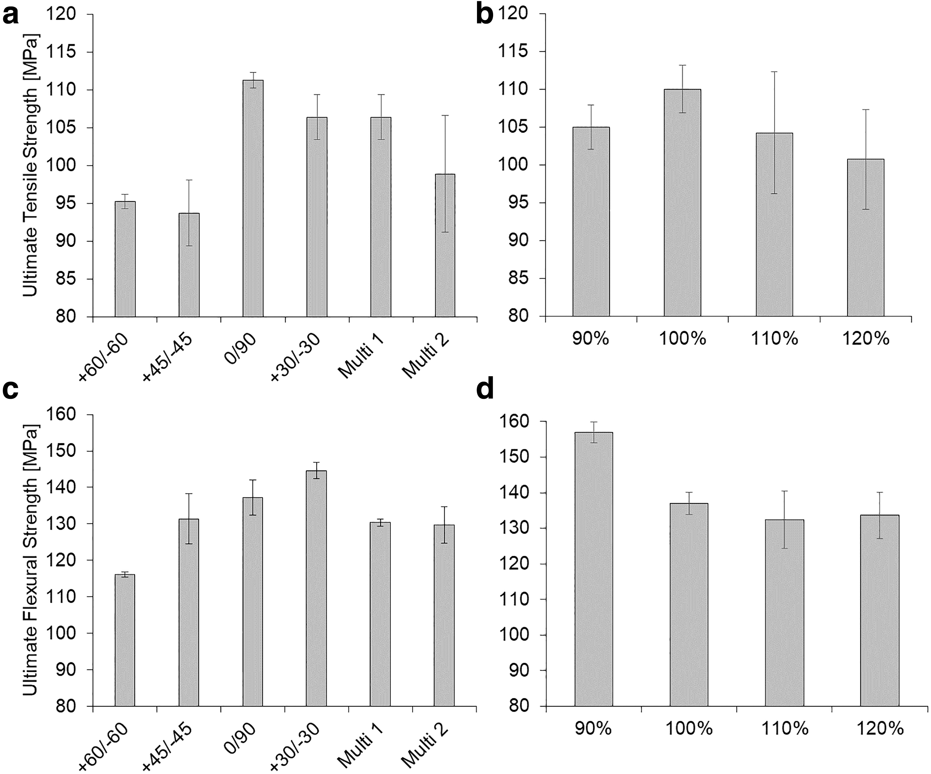
Summary of mechanical characterization.
Trade-Off Between Tensile and Flexural Properties Based on Measured Averages and Min–Max Scaling
When it comes to FFF-printed parts, the raster orientation can significantly affect the mechanical properties of the final product, as observed earlier and as reported elsewhere for other materials.25–27 For both tensile and flexural loads, layers oriented at 0° are generally considered ideal, since the load direction is perpendicular to the weaker inter-road interfaces, leaving these regions less exposed to failure. In this case, the normal load component acting perpendicularly to the inter-road interfaces (i.e., a function of sine of the raster angle) is zero. As the raster angle increases, this normal load component also increases, until reaching its peak at 90°, when the applied load is perpendicular to the inter-road interfaces. Consequently, this is the worst situation concerning raster orientation. 28
For the 0°/90° condition in this study, having half of the layers parallel to the load direction was enough to provide the best trade-off between tensile and flexural properties. As an evident consequence of such a stacking sequence, this condition also appears to be the most advantageous for loads along the width of the part, since rotating the load direction 90° along the same plane results equally in a 0°/90° part (the same is true for +45°/−45° and Multi 1 sequences). The same cannot be said for the second best performing stacking sequence, +30°/−30°, which would become analogous to +60°/−60° if the load was applied along the width.
Since short carbon fibers tend to be aligned parallel to the deposition direction, the reinforcement plays an important role under load.1,29–32 At 0° (Fig. 5a), the dominant failure micromechanism for this material was fiber pull-out, 1 with other micromechanisms also observed, such as a mix of fiber breakage and pullout, fiber breakage (without pulling out), and matrix failure. Overall, these results show a somewhat poor wetting between carbon fibers and PA, which ultimately leads to a weakened matrix–reinforcement interface.

Overview of fracture surfaces after three-point bending test for layers with a raster orientation of
This phenomenon, however, has been reported in the literature for other fiber-reinforced thermoplastic composites as well.29–34 Arguably, the poor wettability between fiber and thermoplastics can be attributed to numerous factors, such as fibers being mostly chemically inert and having smooth surfaces, as well as mismatches in polarity.35–38
At 90°, matrix failure and fiber detachment (evident by imprints; Fig. 5c) were the only mechanisms observed, indicating that supplementary energy-absorbing failure mechanisms such as fiber pullout and breakage were absent in this case. Layers with raster orientations between 0° and 90° (Fig. 5b) exhibited a combination of the aforementioned mechanisms. Although these features were observed on both tensile and flexural fractures, bending specimens showed more evident signs of interlayer delamination (Fig. 5f).
Volumetric flow
Inter-road porosity (Fig. 6) is an issue that is frequently associated with the additive manufacturing of polymer parts by FFF, accounting for a decrease in density of 3D-printed parts. 39 One potential strategy to mitigate the formation of such gaps relies on the increase of the flow rate to induce a road-spreading effect. By spreading the roads to the sides during their deposition, inter-road gaps would theoretically be occupied, increasing part density.
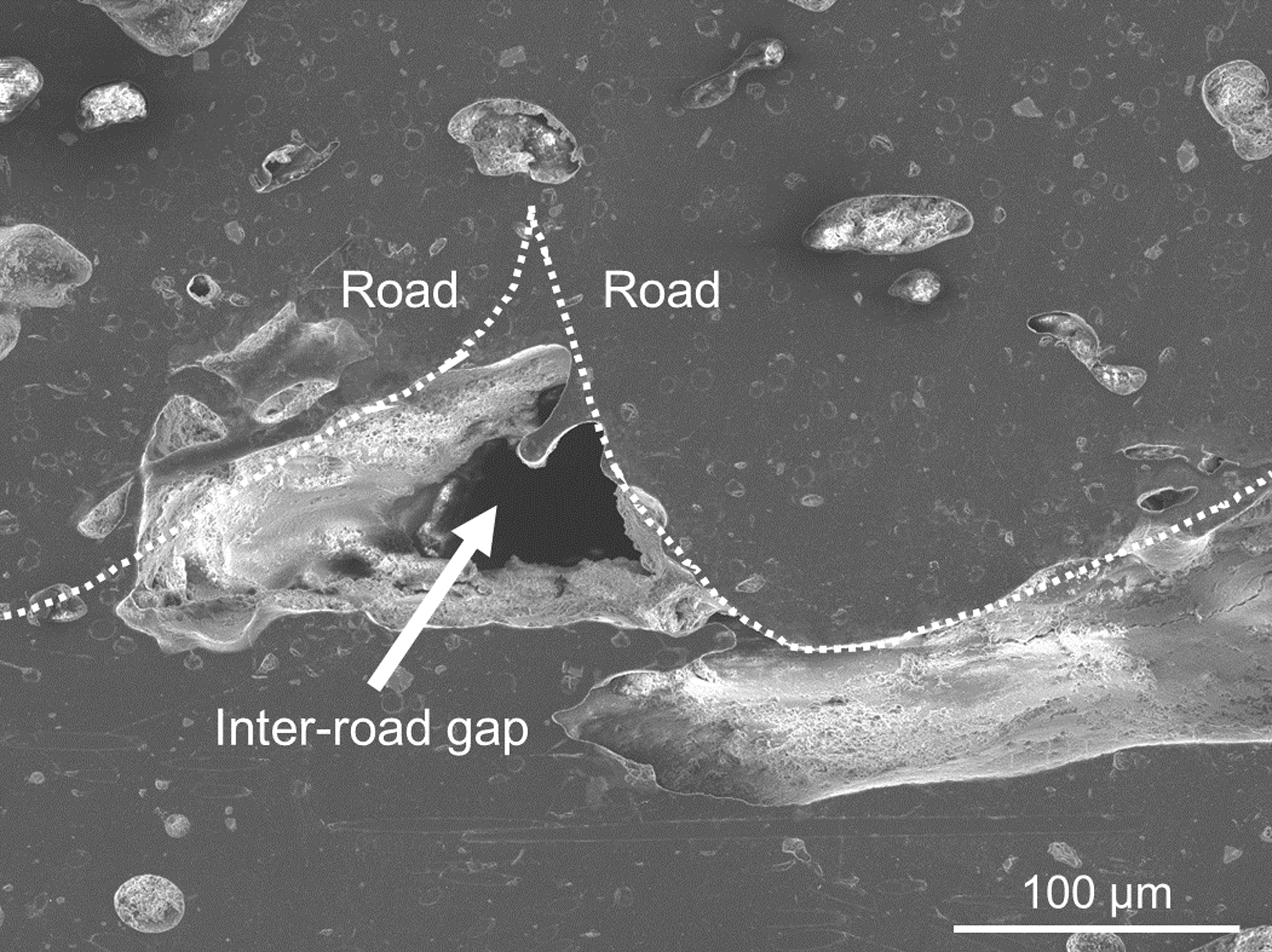
Example of Inter-road gap (arrow) present on as-printed 0°/90° bending specimen.
To evaluate this hypothesis, the flow setting was varied in the slicer software in four levels, as mentioned in 3D-Printing section. Based on the selected process parameters, as well as on the geometry of nozzle and on the dimensions of individual roads, theoretical flow rate values (in mm3/s), as well as expected road radii, were calculated and listed in Table 3.
Theoretical Values for Flow Rate, Extruded Volume, and Road Radius Based on Different Flow Settings
By manipulating the flow setting (and consequently the feeding rate), the first noticeable effect on the printed parts is the surface quality, particularly on the side where the most recent deposition occurred. On those regions, an excess of material could be observed (Fig. 7), when comparing 90% flow with other conditions. However, such a material excess was only moderately translated into an increase in density from 90% to 100% flow, with no significant density increase observed for higher values (Fig. 8b). Therefore, the increase in relative weight with increasing flow (Fig. 8c) can be possibly attributed in large part to the observed material excess on the surface, with the actual density increase playing only a minor role.

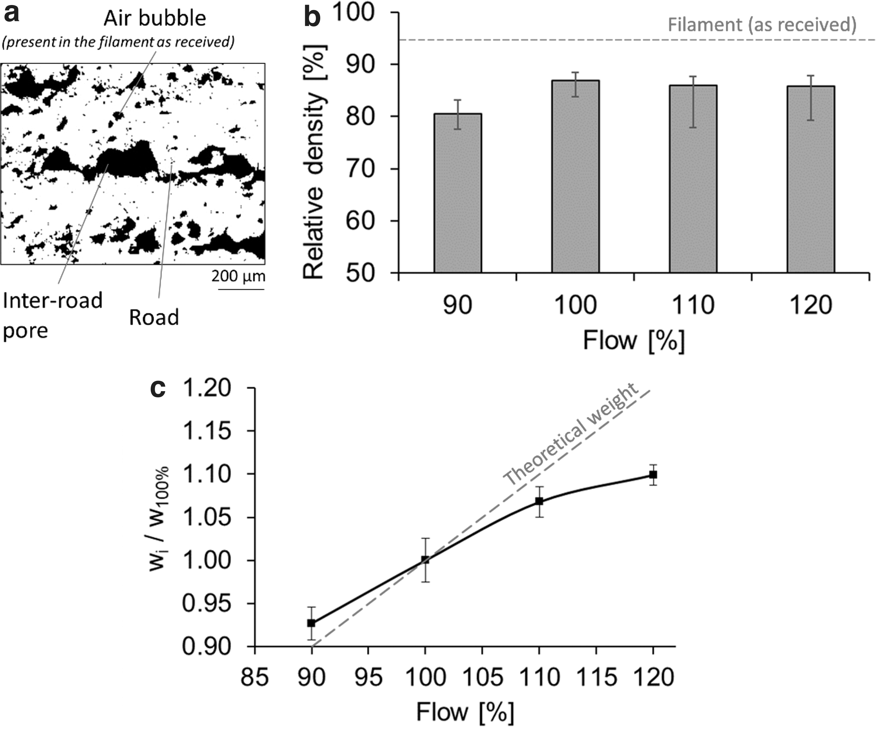
Moreover, the deviation from the theoretical weight indicates that the actual flow rate was most likely lower than the theoretical values presented in Table 3. The reported observations can be reasonably attributed to a possible extrusion rate limit for the present machine/material combination. This would mean that increasing the flow setting beyond 100% would have little to no effect on the extrusion rate itself. On the contrary, by using flow settings exceeding 100%, the faster driving gears may have grinded the filament before the extrusion, changing its original cylindrical shape and dimensions and thus potentially altering the extrusion behavior itself.
Finally, the material excess observed on higher flow settings can be attributed to the oozing phenomena, which is relatively common in FFF 40 and is represented by the leakage of material through the nozzle after the driving gears stopped. This is caused by the relaxation of polymeric chains, which had been compressed and oriented while being extruded as the driving gears continuously pushed more filament through the reduced diameter of the nozzle. When the extruded filament leaves the nozzle in the semimolten state, oriented chains tend to return to their original relaxed state when the load was no longer applied. 41
This is a typical phenomenon found in extrusion of thermoplastics known as extrudate swelling.42,43 Since in the relaxed state the chains occupy a higher hydrodynamic volume, the polymer tends to escape through the nozzle, hence the term “oozing” or “swelling.” The fact that the material excess is only observed at regions where the specimen was 3D printed, the latest (i.e., when the driving gears stopped while the print head moved to the next position) corroborates this hypothesis.
As a consequence of the absence of a clear relationship between density and extrusion rate, no improvement in mechanical performance of 3D-printed specimens was observed beyond 100% flow (Fig. 4b, d). On the contrary, at least with tensile tests, higher extrusion rates appeared to have a potentially detrimental effect on the strength of the parts. However, due to the relatively wide scatter observed for the 110% and 120% conditions, it is challenging to draw further conclusions based solely on these data. As for the flexural properties, reducing the flow setting to 90% resulted in an increase in performance (to some extent) in comparison with other settings.
This can be attributed to the surface quality on the top layer (Fig. 7), which during the bending test was facing downward, as mentioned in Microstructural Characterization section. At 90% flow, the smoother surface contained less stress-concentrating irregularities, which at higher flow settings could have acted as notches, producing premature failure despite the lightly higher density.
Conclusions
In this study, the influence of two infrequently investigated FFF process parameters on the mechanical performance of short carbon fiber-reinforced PA parts was assessed. These parameters were namely the (1) stacking sequence of layers with different raster orientations and (2) the extrusion rate, represented by a flow setting that was calculated as a percentage of the preset road volume.
It was observed that stacking layers with alternating raster orientations of 0° and 90° resulted in the best trade-off between tensile and flexural properties, reaching an UTS and UFS of 111.3 ± 1.0 and 137.3 ± 4.8 MPa, respectively. Another valid alternative was the +30°/−30° sequence, which reached the highest UFS at 144.6 ± 2.2 MPa. Among the studied conditions, +60°/−60° provided the worst trade-off performance. Stacking sequences with more than two raster angles (0°/+45°/90°/−45° and 0°/+30°/+60°/90°/−60°/−30°) resulted in intermediate performances.
The study evaluated the hypothesis that by increasing the extrusion rate while keeping the other process parameters constant, one would be capable of closing out inter-road gaps that are commonly observed in parts 3D printed by FFF. However, based on the current findings, increasing the volumetric flow settings resulted neither in an increase in density nor in mechanical performance. It has been argued that for the setup utilized in this study, there could exist a limit beyond which the actual extrusion rate could not be increased.
Footnotes
Acknowledgments
The authors acknowledge the Open Access Funding by the Graz University of Technology.
Authors' Contributions
C.B. contributed to conceptualization, methodology, formal analysis, investigation, visualization, and writing–original draft. S.T.A.-F. was in charge of resources, supervision, project administration, funding acquisition, and writing–review and editing.
Author Disclosure Statement
The authors declare that the research was conducted in the absence of any commercial or financial relationships that could be construed as a potential conflict of interest.
Funding Information
The study was supported by the Austrian Research Promotion Agency (FFG) [“TAKEOFF” PILOT, grant number 852796, 2018] and the BMK—The Austrian Ministry for Climate Action, Environment, Energy, Mobility, Innovation and Technology.