




Abstract
Scaffolds' designs and physical properties have an important place in tissue engineering. Using different biomaterials, scaffolds with other structures can be developed. The thermal and mechanical properties of biomaterials used in producing scaffolds with the fused deposition modeling method are significant for the application's success. The material must be suitable for both the production method and to be used as a scaffold. Therefore, this study designed three different scaffolds made of the same polylactic acid (PLA) material, but with different lattice structures. To determine the mechanical properties of PLA scaffolds formed, 800 N axial compression load at a 20 mm/min velocity was applied to the samples, with n = 3 in each group. To determine the stiffness of scaffolds, the stress-strain values were calculated by measuring the maximum displacement data under load in each group. Also, finite element analysis was performed on PLA scaffold models. At the same time, scanning electron microscope, differential thermal analysis-thermogravimetric analysis, differential scanning calorimetry, and X-ray powder diffraction pattern analyses were carried out. As a result, it has been concluded that the design significantly affects mechanical properties. Besides the material, the scaffold design is the most important parameter in tissue engineering studies.
Introduction
A
FDM is an extrusion-based, solvent-free AM method that provides more precise and quality products in less time. This method has produced many materials, such as polymers, metal powders, ceramics, and composites. It is still one of the most widely used techniques in bioengineering research due to its low cost, small size, and availability of complex, highly porous scaffold structures.3,4 It is a method of creating 3D designs by filament extrusion from a previously created computer-aided design (CAD) model. The CAD model created with special software on the computer is first converted to STL format and then to G-code format for the 3D printer to detect the structure and print it.
During the production of the designed scaffold model with a 3D printer, there are many essential parameters to obtain the desired precision and smoothness of the structure to be produced. The main ones are printing speed, temperature, layer height, the layout of the part, the diameter of the nozzle, infill pattern, and density.4,5
Using mesenchymal stem cells is widespread in treating bone damage caused by osteoporosis, trauma, diabetes, or aging. In cases where the migration of mesenchymal stem cells (MSCs) from adjacent tissues to the defect site is insufficient for differentiation in severe bone defects, MSCs can be applied more effectively by placing them on the scaffold to differentiate into osteoprogenitor cells at the defect site. 6 The essential parameters to be considered when selecting the material to be used as a scaffold are bioactivity, biocompatibility, and biodegradability.
Polylactic acid (PLA) is a nontoxic, organic, biodegradable, biocompatible polyester classified as a thermoplastic aliphatic polyester obtained from renewable resources such as corn, corn molasses, and beet sugar. Due to its physical and mechanical properties, such as high tensile strength and modulus, good machinability, thermal stability, and low production cost, it acts as a primary organic raw material in additive production using FDM technology.4,6–8
Scaffold design is as crucial as the scaffold production method. The main tasks of scaffolds are to allow sufficient space for the tissue to be regenerated, provide temporary function in the defective area, and be suitable for adding cells and proteins to accelerate tissue regeneration. For a scaffold to function most efficiently in the place where it is implanted, it must show similar properties to the surrounding tissue in terms of porosity, pore size, and mechanical and surface properties.9,10 Today, porous and lattice-based scaffolds can be produced more easily with the help of 3D printing technology. However, the design of scaffolds with desirable properties is still not an easy task.
When it comes to structural design, it is an accepted definition that there is a balance between strength and porosity. Triple periodic minimum surface (TPMS) structures are widely used as bioporous scaffolding units due to their high load-bearing and energy absorption capacity, internal architectures exhibiting specific folds that create smooth and highly interconnected large surface areas. In addition to parameters such as liquid permeability, thermal conductivity, and surface properties for cell adhesion, mechanical strengths were mainly investigated. In addition, the AM method is also suitable for fabricating many TPMS structures.10–12
This study aims to create structures similar to scaffolds used in tissue engineering and compare these structures' mechanical, thermal, and structural analysis results.
Materials and Methods
As a scaffold material, 3D printing (FDM) filaments (Ultimaker B.V., Utrecht, Netherlands), made of PLA having 2.85 mm diameter, were used.
Scaffold design and 3D printing
Three different TPMS and derivative lattice scaffolds (body-centered cubic [BCC], BRA, and UZN) with 8 × 8 × 4 mm dimensions were created in .stl (stereolithography) file format with Autodesk MeshMixer V.3.5.474 (Autodesk, Inc., CA) 3D design software. While BCC is a pre-existing TPMS structure, BRA and UZN are newly designed (Fig. 1). In this study, BCC lattice structure was preferred for comparison purposes. BCC, which is among the lightweight and high-strength multifunctional materials with periodic cellular unit cells, has gained popularity in recent years due to its simple configuration, isotropic structure, and excellent adaptability to the production process. With the rapid development of AM technology and lattice-structured materials, it is a widely used lattice structure.
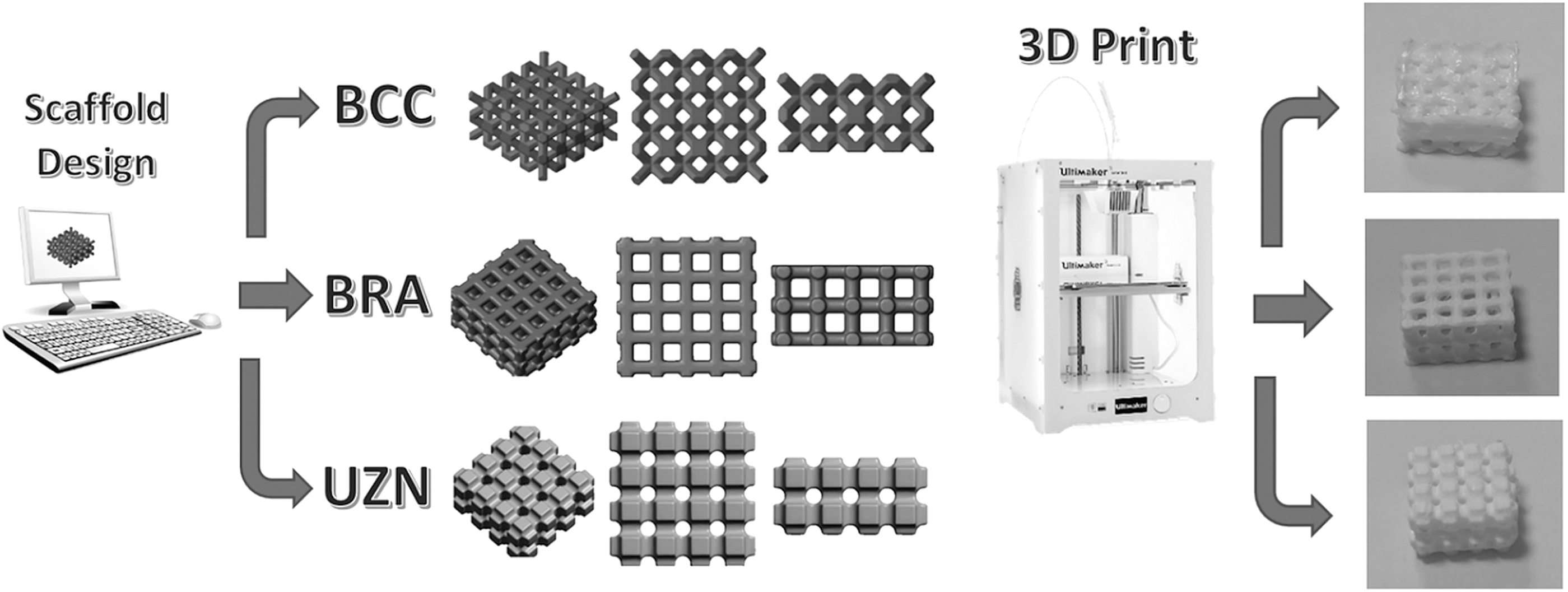
Schematic representation of design and 3D printing processes.
While designing the new cage structures, criteria such as being composed of repetitive unit cells, having appropriate porosity and high mechanical strength, and being suitable for AM methods were taken into consideration. The unit structures of all three lattice models are shown in Figure 2. Pore diameters of samples were as follows: BCC = 400 μ, BRA = 750 μ, and UZN = 500 μ.
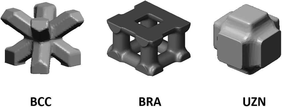
Unit structures of the lattices.
The STL files were imported into the Cura V.5.2.1 (Ultimaker B.V., Utrecht) slicing software for 3D printing. In Cura, previously created models were sliced at the height of 0.06 mm and converted to a G-code format suitable for FDM 3D printing devices (Ultimaker 3 Extended; Utrecht). The printer has a nozzle with a diameter of 0.4 mm that allows the filament extrusion, which is molten at 210°C. Also, the bed temperature was set to 60°C and the print speed was 70 mm/s. Infill rates were set to 100% for all models during the printing phase in order not to affect the mechanical properties of the models.
Analyzes
Scanning electron microscope
All samples were subjected to scanning electron microscope (SEM) analysis to examine the cross-sectional shapes. For this purpose, the surfaces of all samples were sprayed with a thin layer of gold and palladium before analysis. A high-performance, compact SEM (JSM-6060; JEOL, Tokyo/Japan) with 8.00 kV accelerating voltage was used.
Thermal analyzes
Differential thermal analysis-thermogravimetric analysis (DTA-TGA) and differential scanning calorimetry (DSC) values were examined to explore the thermal properties of the material (PLA) from which we formed the scaffolds. DTA-TGA analyses were performed with a DTG device (DTG_60H; Shimadzu, Kyoto, Japan) in an oxygen atmosphere between 25°C and 400°C. DSC analyses were also performed on the TA-Q200 device (TA Instruments, New Castle) at a scanning rate of 20°C/min from 0°C to 200°C for three cycles.
X-ray powder diffraction pattern analysis
X-ray powder diffraction pattern (XRD) analysis was performed to examine the crystal structure of the PLA scaffolds using a diffractometer (PW-1710; Philips, Netherlands). Copper K-α was used as x-ray energy corresponding to an x-ray wavelength of 1.5406 Å. XRD spectra of Raw prednisolone and dexamethasone were recorded by measuring the scintillation response to Cu Ka radiation. A panalytical detector (PIXcel3D; Malvern Panalytical Ltd, UK) was also used to bring data to the diffractometer.
Mechanical tests
To determine the mechanical properties of PLA scaffolds formed, 800 N static axial compression load at a 20 mm/min velocity was applied to the samples, with n = 3 in each group. Since the average human weight is around 800 N and these scaffolds are planned to be used within the bone structure of the human body, first of all, their resistance against this load was tested.
To determine the stiffness of the scaffolds, the stress-strain values were calculated by measuring the maximum displacement data under load in each group.
Finite element analysis
For the finite element analysis (FEA), PLA was chosen as the scaffold construction material and Young's modulus and Poisson's ratio values specific to this material were entered into the analysis software. In addition, rigid plates were modeled on the top and bottom of the geometries to ensure the correct load transfer of axial load to the scaffolds (Fig. 3). Structural steel material properties were selected for these plates (Table 1).
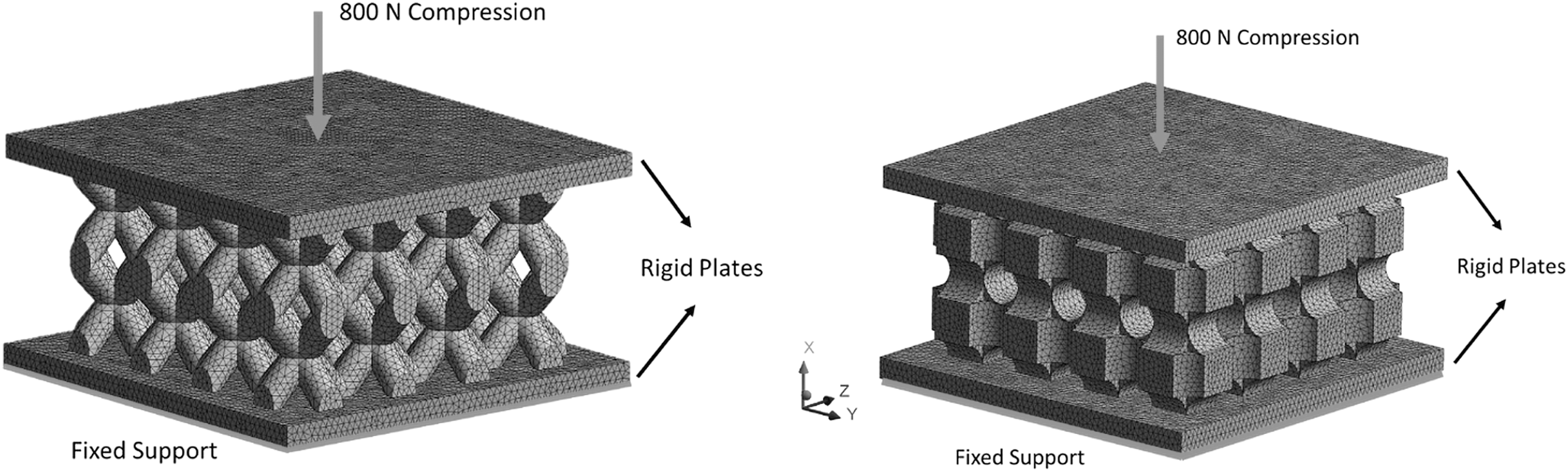
FEA loading conditions. FEA, finite element analysis.
Material Properties Defined for Finite Element Analysis
PLA, polylactic acid.
Mesh properties
All three scaffold models meshed with 10-node tetrahedral elements using ANSYS Workbench (ANSYS, Inc., CA) software. BRA, BCC, and UZN finite element models consist of 713325, 576293, and 932540 nodes, respectively. The number of nodes they contain differs since their geometrical features varies extensively.
Boundary conditions
800 N Compression load was applied to the upper free rigid plates and the bottom rigid plates were fixed. Von-Mises stress values are examined.
Results and Discussion
Methods of measuring how some properties of polymeric materials change with temperature are called TGA or thermal analysis. The most commonly used methods in these analyses are TGA, DSC, and DTA. It is a critical analysis to determine the characterization of the polymer and its thermal stability, representing the highest temperature it can withstand before thermal degradation. 13
DTA-TGA analysis
The thermal behavior of polymer material dried at 50°C for 1 h in the air is depicted. DTA-TG curve revealed that thermal behaviors of the material are observed at temperatures between 35°C and 400°C. The TG curve, illustrated in this case for polymeric material, offers a weight loss of about 35% for temperatures from 35°C up to 400°C. The first thermal phenomenon was solvent removal at a temperature of ∼85–90°C.
The thermogravimetric study linked with the TGA showed evidence that the PLA material exhibited the same thermal behavior. The thermogram was produced by heating the precursor of the material between room temperature and the temperature at which mass losses were indicated in the TG curve. Nevertheless, the first mass loss was observed in the temperature range of approximately 315°C and the second, representing the most critical mass loss, was observed at about 370°C (Fig. 4).
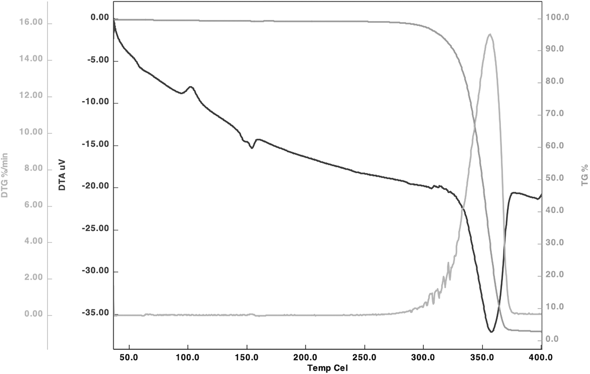
DTA-TGA thermogram analysis results. DTA, differential thermal analysis; TGA, thermogravimetric analysis.
These mass losses, which were described previously, were confirmed, in the DT curve, by the presence successively of a broad endothermic peak, which has been attributed to the evaporation of physisorbed water and solvents such as ethanol, a narrow exothermic peak that was assigned to the departure of residual organic compounds, and a vast exothermic peak centered.
DSC analysis
DSC measures temperature and enthalpy related to many thermal processes, such as melting, crystallization, glass transitions, and decomposition reactions, by applying linear heating and cooling to a material. 14
The enthalpies for cold crystallization of PLA filament (23 J/g) and ultimate melting (24 J/g) are provided. The absence of peaks in the XRD spectra of scaffold filaments is consistent with the melting of PLA during the DSC analysis, dissolving the crystallization on the strand surface, leading to the observed result. In addition, PLA's melting enthalpy (24 J/g) was higher after partial swelling and gradual evaporation, although the cold crystallization enthalpy was lower.
DSC investigations of water and slowly-cooled PLA have good thermal stability above the midpoint degree (T = 54.23°C) and the amorphous specific heat-temperature dependence is established. It is drawn directly onto the DSC thermal response above the peak temperature of 98.96°C and then extrapolated to the ambient temperature. The water and the sample chilled slowly had fractional crystallinities, and the slow-cooled sample was 23.756 and 24.140 J/g, but the water had a lower value (Fig. 5A). The weight percent crystallinity assessed by glass transition was comparable to these values. In such a scenario, the degree of crystallinity must be calculated at the same temperature; if this is not done, there is no way to compare the values with those established by other methods.

XRD analysis
The PLAs collected had a diffraction pattern with three notable peaks at coordinates 18.08, 36.07, and 41.28 (Fig. 5B). PLA has a well-organized packed crystalline structure, as shown by the enhanced intensity of the peaks. The d-spacing of the studied PLA sample shows the model's well-organized crystalline structure (peaks; 5.68, 3.25, and 2.76, respectively). This theory assumes that the surface C, H, and O concentrations are low enough for rapid and total dissolving in molten PLA.
SEM analysis
The variety of pore diameters could be seen in the SEM pictures of the surface and the cross-sections of the material. As the material's porosity increased, the pore diameters expanded in all directions, regardless of the geometry type. When the SEM images were examined, it was seen that the BCC and BRA samples had a relatively more stable and versatile square pore structure in their surface and cross-sectional views. It has been determined that the UZN sample has a spherical structure with a somewhat smaller pore size in three axes (Fig. 6).

SEM image of UZN, BRA, and BCC surface and cross-section. BCC, body-centered cubic; SEM, scanning electron microscope.
Mechanical analysis
According to the mechanical test results, while the strain values in BRA and UZN were close to each other, it was observed that the strain was ∼7 times higher in the BCC scaffold. Since the force applied to the specimens was constant (800 N) and the cross-sectional areas were the same, the resulting stress values were also the same. The stiffness values of all three samples were calculated and it was observed that the most rigid scaffold was UZN with 4395.604 N/mm stiffness value, while BRA had 3478.261 N/mm and BCC had 583.941 N/mm. Also, strain values of BCC, BRA, and UZN were 0.3425, 0.0575, and 0.0455, respectively.
Based on the stress and strain values, the elastic modulus of each scaffold was calculated as BCC = 72.9927 MPa, BRA = 434.6579 MPa, and UZN = 548.4471 MPa, respectively (Fig. 7).
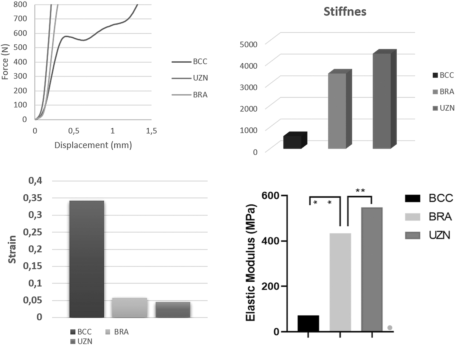
Force-displacement, strain, and elastic modulus diagrams of the scaffolds.
Finite element analysis
When the results of the FEA were examined (Fig. 8), it was seen that the highest stress value was found in the BBC to be compatible with calculations in the mechanical tests (Table 2). Likewise, the most rigid scaffold was found as UZN. Effective modulus values were also calculated according to the FE analysis data, and it was seen that the BCC scaffold had the lowest value (Fig. 9).
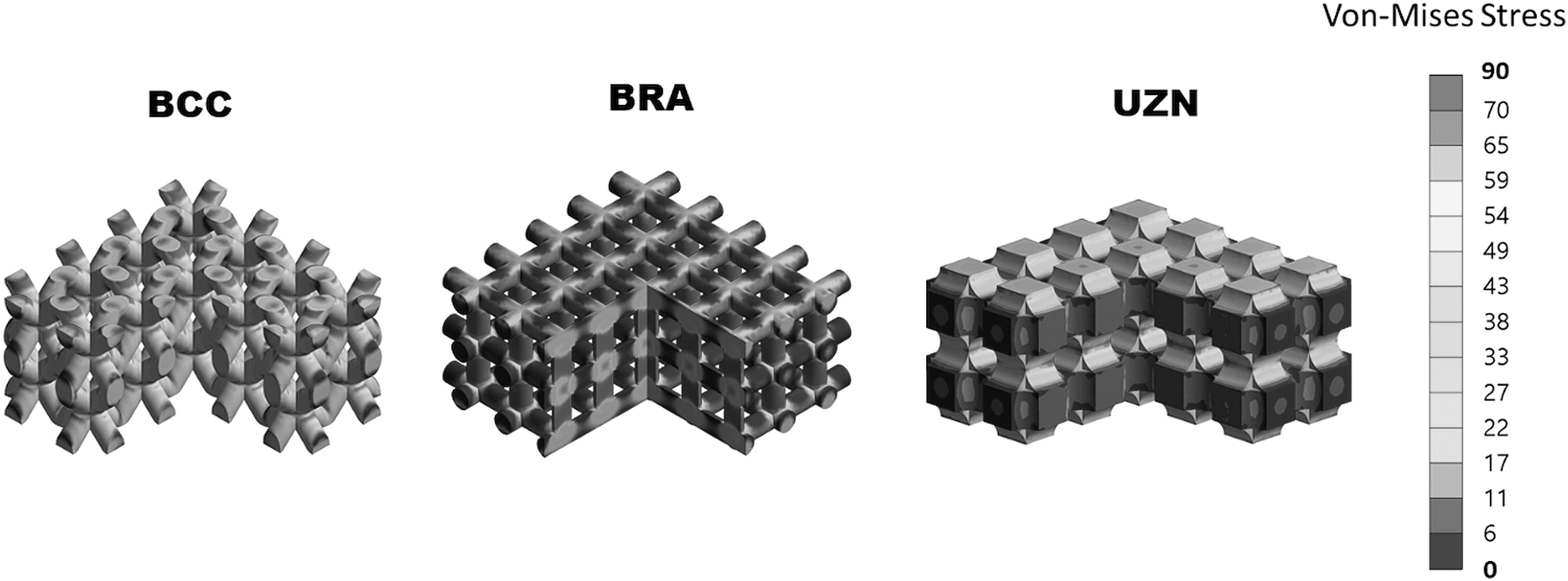
Von-Mises stress values of the scaffolds.

Stiffness and effective module results of FEA.
Finite Element Analysis Results
BCC, body-centered cubic.
Conclusion
Similar values were observed when the results of mechanical tests and finite elements analysis were compared. In both evaluation methods, the BCC scaffold was the weakest and the UZN scaffold was the most durable. However, BCC values in mechanical tests differ much more than the other two groups. In the FE analysis, such a difference was not observed between them. We think this is because the print quality of the BCC sample coming out of the 3D printer is lower than the model in the virtual environment. Because its structure is quite complex for 3D printing. It has been accepted that the difference is due to this situation.
The type of material used and the scaffold structure are the most critical parameters affecting the scaffold mechanical properties. PLA is superior to many biomaterials in terms of mechanical and thermal properties. However, the structure of the scaffold and the type of cage significantly change the mechanical behavior. Therefore, mechanical strength and pore structures should be considered while designing the scaffold, and the design and production should be planned in line with the desired values according to the region where the scaffold will be applied.
Footnotes
Acknowledgment
The authors wish to thank Prof. Dr. Osman Çulha for his technical support.
Authors' Contributions
Conceptualization: B.U. Data curation: B.U. and O.C. (mentioned in acknowledgment). Formal analysis: B.U. Funding acquisition: No funding. Investigation: B.U. Methodology: B.U. Project administration: B.U. Resources: previously owned. Software: previously owned. Validation: O.C. (mentioned in acknowledgment). Visualization: B.U. Writing—original draft: B.U. Writing—review and editing: B.U.
Author Disclosure Statement
No competing financial interests exist.
Funding Information
No funding was received for this article.