
Abstract
Fused Filament Fabrication (FFF) printing is one of the most all-purpose manufacturing techniques, allowing many complicated parts to be obtained at lower cost. This is especially important in prosthetics, where more complex prostheses, especially of a hand, can cause enormous expense. However, providing the full functionality of a prosthesis often requires combining materials with different properties, such as rigidity and flexibility. The use of such a combination in multi-material printing involves a problem of delamination at the interface between two materials. The research described in this article focused on modifying the structure of the interface to improve adhesion between rigid and flexible materials. Polylactide (PLA), thermoplastic polyurethane (TPU), and acrylonitrile butadiene styrene (ABS) were used. PLA-TPU85, PLA-TPU98, ABS-TPU85, and ABS-TPU98 joints were tested in a three-point bending test. Among the above-mentioned joints, the one called PLA-TPU85 presented the best properties, that is, the ability to transfer forces. Therefore, this joint was selected for further modifications. To improve the adhesion in PLA-TPU85 joint, a sandwich-type structure was designed, and its effectiveness was tested in a shear test. The samples lacking this structure became delaminated during the test, whereas those with the sandwich structure maintained the integrity. Thus, the effectiveness of such a solution was confirmed and applied to the connection of rigid and flexible materials in the final printing of the prosthesis.
Introduction
Fused Filament Fabrication (FFF) printing has many advantages, including low printing costs, which allows for a wide range of applications, including prosthetics.1,2 This increases the availability of prostheses for patients with limited budgets, even allowing them to print prostheses on their own.3,4 In addition, the possibility of multi-material printing using the FFF method allows the prosthesis to be enhanced and improves its properties by using different materials.
A prosthesis, especially a prosthetic hand, must meet many different requirements. Let us mention just a few of them: the resistance to moisture, the ability to bear mechanical loads, and biocompatibility (at least the materials used in it would not irritate the patient's skin). The design of such a prosthesis should also be balanced in such a way that it could not cause too much strain on the body, as this can lead to curvature of the spine.5,6 Hand prostheses can be mainly divided into cosmetic and active ones. The main purpose of the former is to provide as accurate reproduction as possible of the lost limb, but often there is no possibility to move them.7–9 In contrast, the task of active prostheses is to allow the patient to return to real life as they allow to do everyday life activities.8–10 It is their improvement that is currently being worked on. Their design and function are being analyzed,11–15 as well as the possibility of using 3D printing in their manufacture.4,16–20 The possibility of improving such printing is also being considered.
There are several ways to modify classic single-material printing. It is possible to use two print heads to print different materials, mix two polymers into one blend, or use special filaments reinforced with glass or Kevlar fibers.21–24 However, multi-material printing has disadvantages and limitations in addition to its possibilities.25,26 These are related to equipment and materials. Printer-related problems include the limitation of the printing area caused by the presence of an additional extruder and the calibration of both extrusion heads, which can take a long time. 21 Problems related to materials arise from their different chemical nature and printing parameters such as printing temperature.
The chemical nature can affect the adhesion of the filaments and their delamination. In addition, between materials, a boundary interface is formed during printing, which would cause weaker adhesion of the materials in case of discontinuities. Therefore, during multi-material printing, it is important to pay attention to parameters such as printing temperatures and speeds, on which the quality of the final product will depend.27–30 Postprocessing also affects the final quality of the joint. 31
The quality of prints can be improved by, among other things, changing the orientation of the printed filaments and applying layers of the infill pattern from a different angle.32,33 Increasing the adhesion between different filaments can also be achieved by using mechanical interlocking at the border between them.34–40 A macroscopic interface can be designed so the bonding element between materials could be based on the interlocking mechanism. In the case of the microscopic interface, the adhesion between materials is based on the occurrence of chemical bonds or chemical interactions between materials. The third type of interface—a mesoscopic one—is a solution bordering on macroscopic and microscopic interfaces. 34
Ribeiro et al. 34 investigated the effect of T-shaped, U-shaped, and dovetail interlocks on the adhesion between polylactide (PLA)-PLA and PLA-thermoplastic polyurethane (TPU). The results of the tensile test showed that the tested macroscopic interfaces provided better mechanical properties of the print than the microscopic interfaces. Frenkel et al. 35 in their study also demonstrated increased adhesion between different filaments by producing a mesoscopic interface. The fabricated tensile test specimens consisted of two halves printed from polyethylene terephthalate glycol and TPU. They had a mesoscopic interface produced by printing layers so that they could overlap, creating mechanical interlocks that positively influenced the tensile strength of these specimens compared with specimens with a flat interface. The use of sandwich structures, in which layers of different filaments are printed by turns, also appears to be an interesting solution. It increases the contact area between the layers and can positively influence the adhesion of materials. 36
In this article, we describe the possibilities for improving the adhesion of two different materials, which were printed using the direct nozzle-feed FFF multi-material printing method. The investigated adhesion improvement possibilities are related to the improvement of mechanical joints that can be used in the fabrication of a hand prosthesis.
Materials and Methods
Sample preparation
The test samples were produced using the FFF technology in a Raise3D E2 printer. This printer has two nozzles with a filament feeder directly to the nozzle. For samples that are a combination of two materials, the flexible filament was printed on top of the rigid filament, due to indications in the literature that better adhesion of the materials to each other is achieved.
Two rigid and two flexible filaments were used for testing (Table 1). Information about the used filaments and their printing parameters is summarized in Table 1. The samples were printed with 100% infill.
Information about the Filaments Used and Their Printing Parameters
ABS, acrylonitrile butadiene styrene; PLA, polylactide; TPU, thermoplastic polyurethane.
Three-point bending test
To select the best initial combination of rigid and flexible materials for further modification, a three-point bending test was conducted. It was decided to carry out this type of testing because of the occurrence of this type of loading in prosthetic hands during daily activities. The conducted test was based on PN-EN ISO 178:2019.
The specimens were in the shape of a cuboid with dimensions of 80 × 10 × 4 mm, which was divided lengthwise in half. The design of the samples in the Onshape program is shown in Figure 1A for samples that were printed from a single material, while Figure 1B shows samples that were a combination of two materials. The following filament configurations were tested: PLA-TPU 85A, PLA-TPU 98A, acrylonitrile butadiene styrene (ABS)-TPU 85A, and ABS-TPU 98A.

Sample design for the three-point bending test:
Three-point bending was carried out on a 50 kN LVV testing machine from Walter Bai. Because the flexible filament is to make it easier to grip different objects, a specimen consisting of two filaments was placed in the machine so that the load was applied to the part printed from the flexible filament (Fig. 1C). The test speed was 0.05 mm/s.
Filament interface modification
To increase the adhesion between the filaments, a sandwich-type structure was designed to achieve a more developed contact surface between the filaments. The proposed structure consists of three layers, where each layer is made of alternating strips of PLA and TPU, and adjacent layers are arranged at 90° angles to each other (Fig. 2A–C).
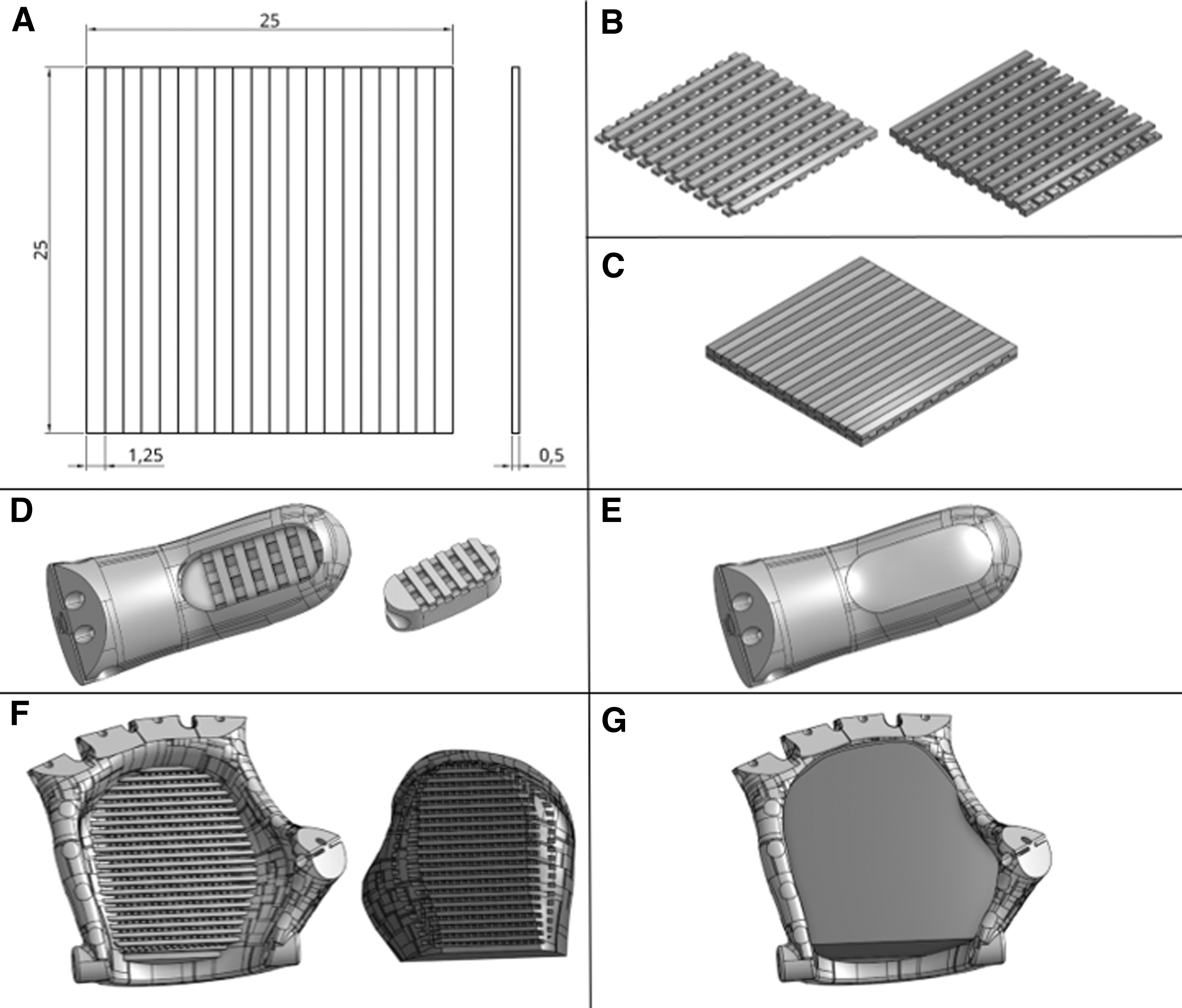
Dimensions of one sandwich layer
The prosthesis design was downloaded from the E-NABLE website. 41 In the original design, the phalanges had silicone-cast components inside. In the present study, the design was modified so that in place of the silicone elements there is TPU connected to the phalanx with PLA through a sandwich-type structure (Fig. 2D). In addition, the filling of the palm was made of TPU. Then, it was connected to the PLA part also through a sandwich-type structure (Fig. 2F).
Testing adhesion at the filament interface
Based on the three-point bending test, the PLA-TPU 85A combination was selected for further testing. The effect of the interface modification on the adhesion of PLA to TPU 85A was tested on the basis of PN-EN 1465:2009 with an increased bonding area to insert the sandwich structure. The samples were in the shape of two cuboids (100 × 25 × 1.6), overlapping each other by 25 mm. The design of the specimens in the Onshape program is shown in Figure 3A for the specimens without the modified interface and in Figure 3B for the specimens with the sandwich structure, described in the Filament Interface Modification section.

Design of samples for the adhesion test:
The test was conducted in the LVV 50 kN testing machine from Walter Bai, and the test speed was 1 mm/s.
Results and Discussion
Three-point bending
To obtain statistics of the results, three-point bending was carried out using five specimens of each type. Statistical analysis was based on mean and standard deviation of force. The results included data representing the force value at a given displacement. Extreme values were discarded, and the means as well as standard deviations were calculated from the remaining three specimens. Based on these data, a force–displacement relationship graph was made for each material (Fig. 4).
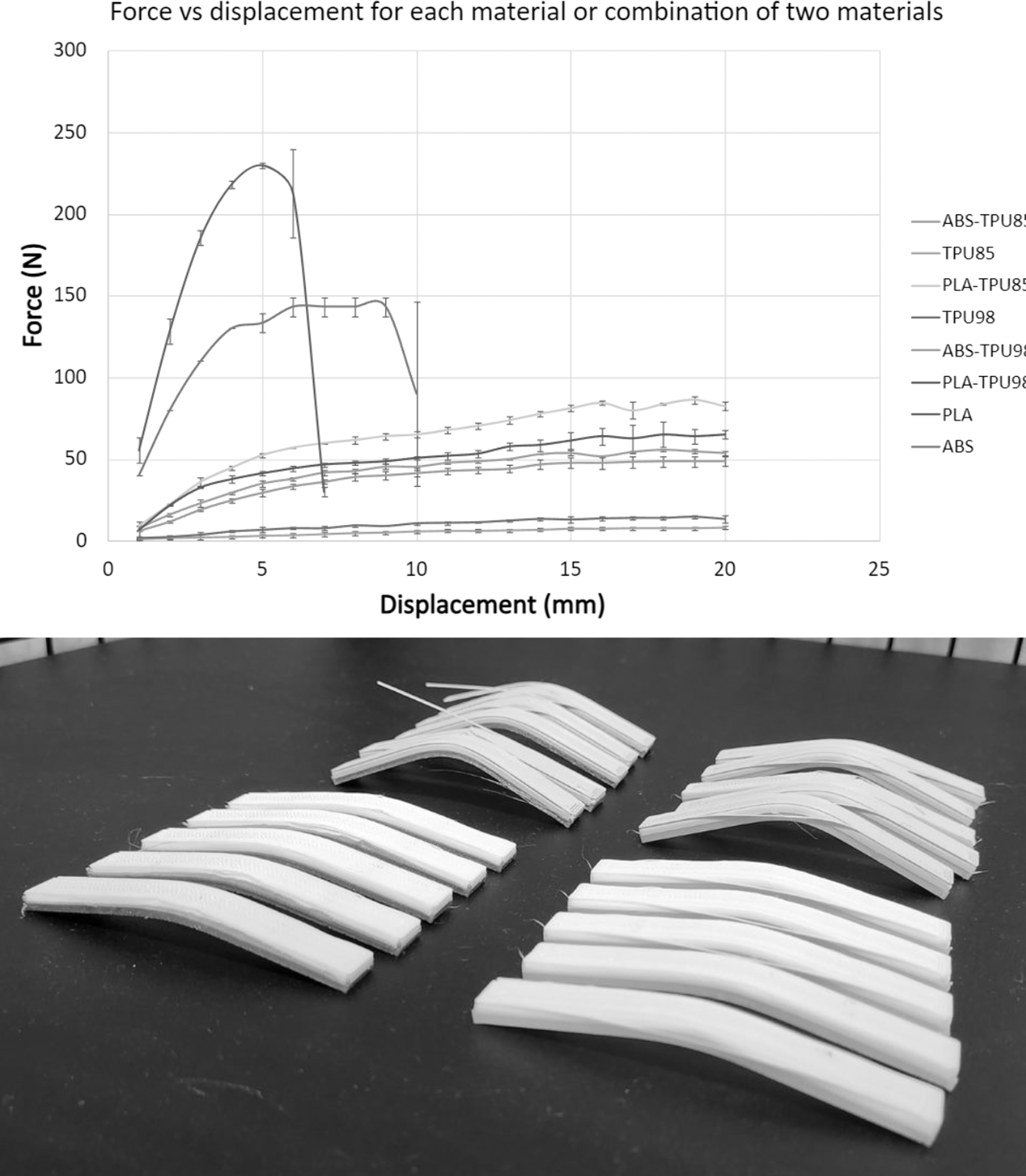
Force–displacement relationship for three-point bending (top) and the photo of samples composed of two materials after testing (bottom). ABS, acrylonitrile butadiene styrene; PLA, polylactide; TPU, thermoplastic polyurethane.
The highest force values occurred for samples made of PLA and ABS. The forces found in PLA obtained values of >230 N, whereas ABS obtained values of <150 N. Subsequent samples obtained much lower values. PLA-TPU85 had force values of about 90 N. The samples with the lowest force values turned out to be below 10 N for TPU85 and around 15 N for TPU98.
The highest forces can be carried by samples made of rigid filaments, however, at higher deformation they break. The lowest force needed to deform the material is for both samples made entirely of flexible materials. They, however, were not destroyed. In contrast, it can be seen that the four groups of samples made from both filaments share the above characteristics. They can all transmit higher forces due to the reinforcement of the rigid material, but they do not break thanks to the connection to the flexible material.
The combination of materials for which the highest strength was obtained was PLA-TPU85A combination, so it was selected for further modifications. The interface of these filaments was modified in subsequent samples using a sandwich structure.
Shear test
To study the effect of material bonding modifications, a shear test was carried out on four types of specimens: those containing a sandwich-type bond and those containing a non-sandwich bond for two different materials, as well as for single materials PLA and TPU85. The results obtained were presented graphically in the form of force–displacement relationship graph. To obtain statistics for the results, the shear test was carried out on four specimens of each type. Statistical analysis was based on mean and standard deviation of force (Fig. 5).
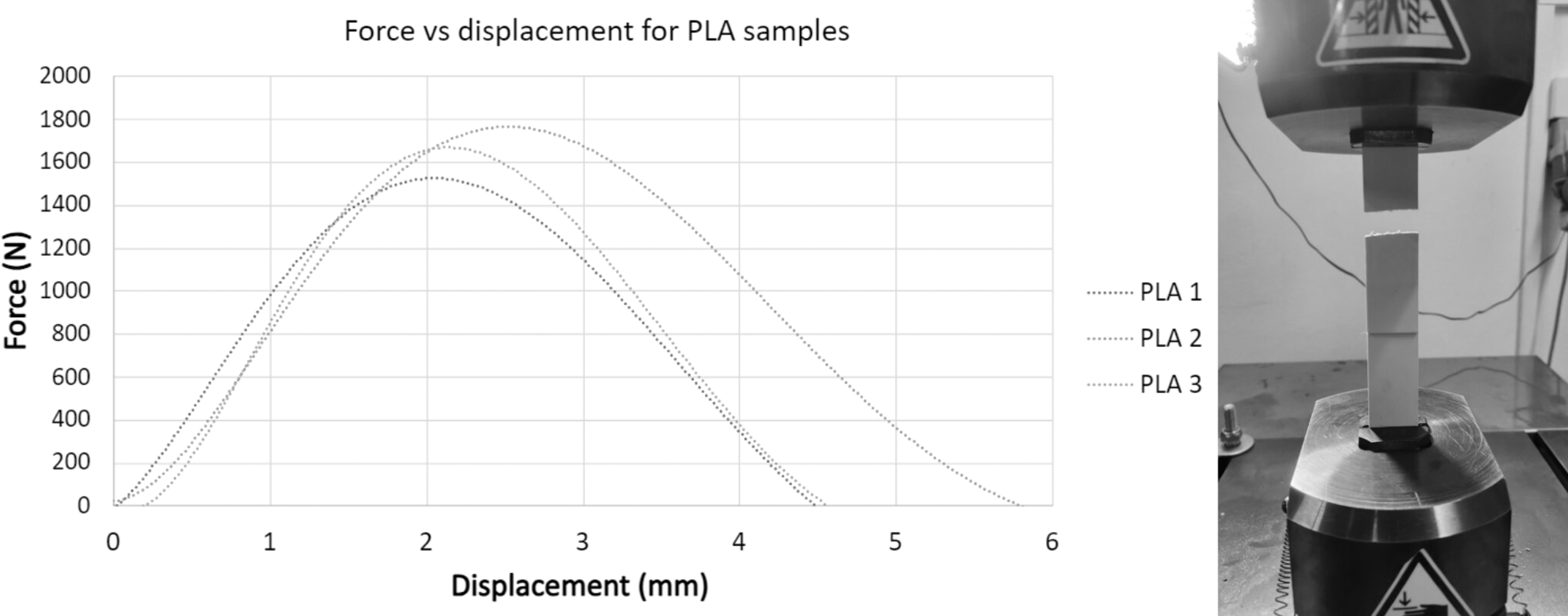
Force–displacement relationship for samples made of PLA (left) and a sample of PLA subjected to stretching (right). PLA, polylactide.
The highest force values among all the samples occurred for PLA and amounted to >1500 N. They were more than seven times higher compared with the samples containing a sandwich-type joint. However, the samples made of PLA were ruptured very quickly when the displacement was as little as 5 mm. The destruction occurred on the thin part of the sample, not on the bonding (Fig. 6).

Force–displacement relationships (left) for samples made of TPU85 (top), samples without sandwich connection (middle), and samples with sandwich connection (bottom), and analogous photos of samples subjected to tension (right).
The samples made of TPU85 were not ruptured in the tested range. On the contrary, the maximum force values obtained were 170 N. TPU85 as an elastic material underwent elastic deformation. The adhesive overlap similar to PLA remained intact.
The samples without a sandwich connection were ruptured between 80 and 90 mm and a force of 170 N. During stretching, the specimen showed performance analogous to the TPU85 specimen, so it can be seen that it was the material that worked during stretching. However, the interface between the two materials did not provide sufficient adhesion, resulting in a complete separation of the two materials.
The samples with a sandwich connection were not ruptured within the tested range. When stretched to 100 mm, the resulting forces did not exceed 200 N. Again, these samples show performance, which is analogous to the TPU85 specimen. However, unlike in the case of samples made of two materials without a sandwich-type structure, the ones with a sandwich structure were not ruptured. It showed that the sandwich-type structure, implanted inside, prevented dislodging.
To analyze the obtained results in more detail, the averaged values for the three measurements of the tested materials were compiled on a single graph, except for PLA, which had significantly higher values. In addition, the standard deviations are included (Fig. 7).
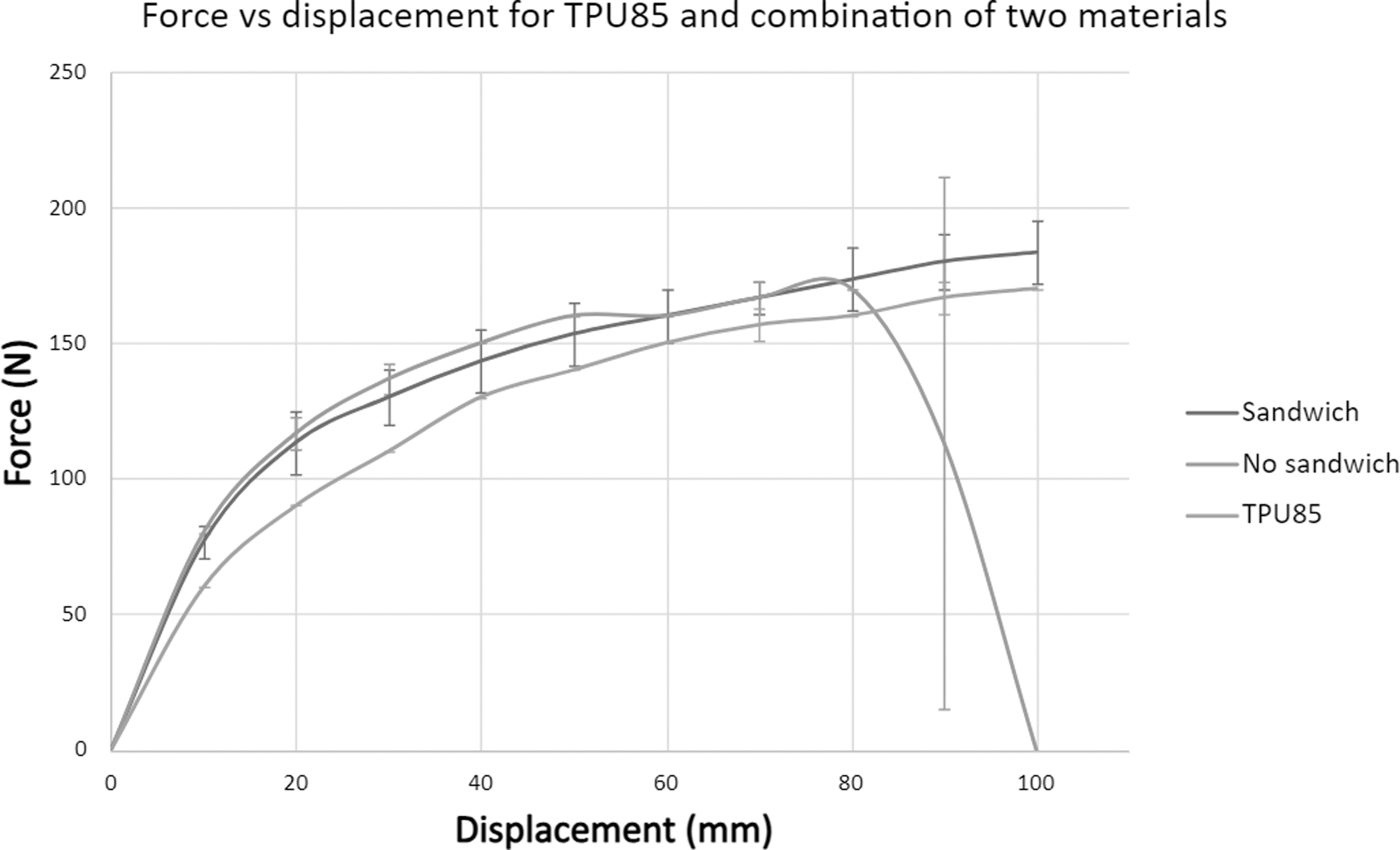
Cumulative graph showing force versus displacement for TPU85 samples and samples from two materials with and without a sandwich structure. TPU, thermoplastic polyurethane.
The sandwich connection was characterized by a lack of rupture and maximum forces of about 180 N. In the specimen with the classic connection, the rupture of the materials occurred at a displacement between 80 and 90 mm and a force of about 170 N. The sample made only of TPU85 did not break, and the maximum force values obtained were 170 N, as in the case of the samples without sandwich connections. As can be seen, the samples printed from the two materials had similar characteristics to TPU85, but thanks to the connection with PLA, they could carry slightly higher forces. At the same time, inserting the sandwich structure into the interface between the materials not only strengthened it but also prevented the materials from breaking apart.
Conclusions
The research carried out not only made it possible to select the best combination of rigid and flexible materials from among the most popular materials but also to test a surface modification that additionally strengthened the multi-material print.
During the three-point bending test, it was shown that creating such prints from rigid and flexible materials combines the advantages of both. On one hand, the rigid material (PLA and ABS) strengthens the print, allowing it to handle greater forces. On the other hand, the flexible material (TPU85 and TPU98) prevents cracking. Thanks to the relatively high strength properties of PLA and the significant increase in the flexibility provided by TPU85, the combination of these two materials had the best bending strength properties.
Modifying the contact surface of these materials by inserting a sandwich-type structure significantly increased adhesion and prevented delamination at the interface and thus rupturing of the prints. This was confirmed by tensile tests that introduced a shear force at the interface boundary.
The structure tested in this way was used in the prosthesis printing process to improve the attachment of the flexible material. In this way, a fully functional model was printed (Fig. 8) and created from PLA and TPU85 selected in earlier tests, joined by the designed sandwich structure.
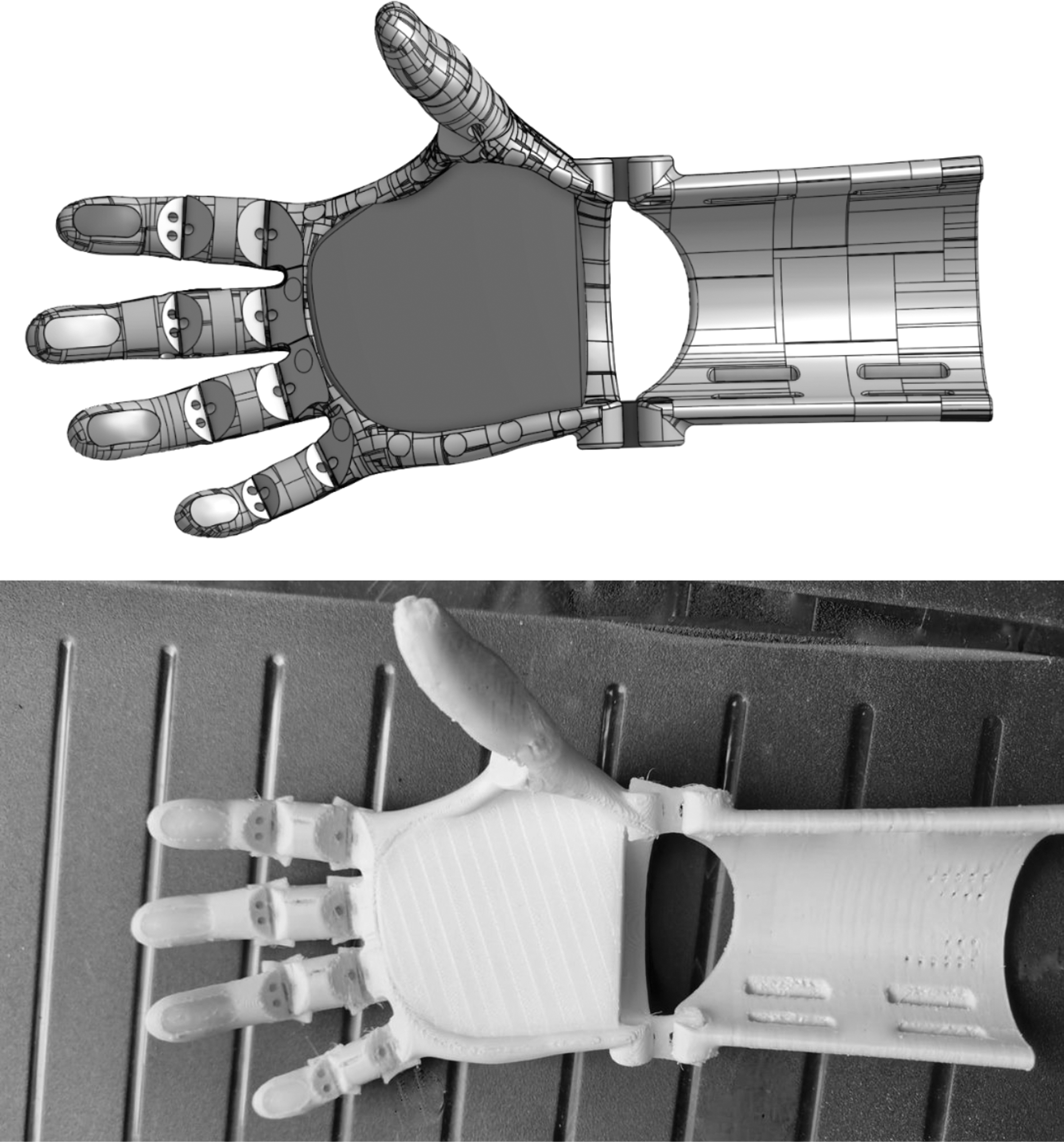
Hand prosthesis: Onshape assembly image (top) and printed model (bottom).
Footnotes
Acknowledgments
This work was completed when the first author was the Doctoral Candidate in the Interdisciplinary Doctoral School at the Lodz University of Technology, Poland. The authors duly acknowledge Laura Ciosek and Piotr Stanisławek for support and sharing their wisdom during the research. The authors would also like to thank Get 3D Ltd. Company for their technical support and consulting.
Authors' Contributions
E.B.-S.: Conceptualization, funding acquisition, resources, supervision, writing—review and editing. N.S.: Investigation, methodology, visualization, writing—original draft. P.S.: Formal analysis, investigation, visualization, writing—original draft. K.W.: Investigation, methodology, visualization, writing—original draft. J.S.: Conceptualization, project administration, supervision, writing—review and editing.
Authors' Disclosure Statement
No competing financial interests exist.
Funding Information
Project funded by the Empiria and Knowledge Foundation under the “Talents of Tomorrow” program.