
Abstract
The manufacturing of parts with medium complexity using wire-arc directed energy deposition (waDED) gets constantly improved by the development of tailored alloys and improvements in the generation of welding paths. In this study, both aspects are considered by proposing a novel aluminum alloy based on Al-Mg-Zn, which is then used for the waDED manufacturing of a car rim. The alloy was characterized in small-scale samples, in which no hot cracks and only a few gas porosities were found. In addition, the high quality of the alloy was verified by tensile tests of the heat-treated samples. The determined yield strength was >365 MPa, the ultimate tensile strength was >450 MPa, and the fracture strain was at least 3.9%. To put the new alloy to use, a standard aluminum car rim model was modified for the needs of waDED. Difficulties due to the steep overhang of the outer ring in the intersecting area with the spokes could be resolved by utilizing and adapting the collision avoidance of the path generation tool in the critical area. The optimization of the welding paths was simplified by first planning the paths using a section of the rim model. The rim geometry was manufactured successfully, and valuable findings regarding the waDED process of parts with medium complexity could be derived.
Introduction
The directed energy deposition (DED) process uses a wire or powder, which is deposited into a melt pool generated by a high-energy source. The wire-arc directed energy deposition (waDED) process is a subset of DED that uses an electric arc to create the melt pool in which the wire is fed. 1 The arc generation process differs between gas metal arc welding (GMAW), where the welding wire serves as both the electrode and the filler material, and gas tungsten arc welding (GTAW), where a nonconsumable tungsten electrode is used to create the arc and the filler material is separate and gets fed into the pool. 2 The waDED process can be used to manufacture parts with low to medium complexity and, until now, is mainly used in aerospace, repair, and high-performance applications.3,4
The main benefits, compared with other additive manufacturing processes, are the high material deposition rate1,5 and the wide material availability of welding wires 6 due to decades of innovation in welding technology as detailed in Ref. 7 The ongoing development on materials,8,9 process stability,10,11 and programming tools12–14 constantly widens the areas of application for waDED.
In the development of new alloys for the waDED process, usually straight walls are manufactured to conduct material property characterizations. 8 While this is sufficient for the characterization of microstructure and mechanical properties, often deviations in terms of build quality can be observed in the manufacturing of complex structures.13,15 Reasons can be, for instance, variations in stepover distance 13 or deviating interlayer temperatures due to model shape and size compared with the manufacturing of a wall geometry. Also, the properties of an alloy need to be explored to demonstrate its potential for waDED of complex-shaped components. Automated path generation for computer-aided design (CAD) models is used to create structures with higher complexity using waDED.12,14,16,17 Software tools for path generation are still under development.
As shown by Venturini et al.,15,18 the detection and compensation of intersecting single-wall geometries and also multitrack geometries 19 are major concerns in waDED. The ongoing improvement of the manufacturing strategies combined with alloy development tailored for the process is considered to have a major impact on the future economic viability of waDED.
As can be seen in Refs.,17,20,21 various steel and aluminum single-track waDED parts with medium complexity have been studied extensively, while multitrack parts remain a less inspected area in research. The reason for that can be that path generation algorithms or collision avoidance strategies are still to be improved, to reliably produce multitrack parts.12,16,17,22 Commercially available software already supports most of the current path generation algorithms shown by Lin et al. 23 The algorithms are combined with tooling controls adapted from multiaxis machining operations.
Cold metal transfer (CMT) is oftentimes used to manufacture parts in waDED. This process is a variation of GMAW and provides benefits such as a high deposition rate, stable arc, and no spattering while reducing the heat input compared with conventional GMAW processes.11,24,25
In this work, we aim to contribute to the advancement of the waDED technology by demonstrating a combined approach of alloy development and fabrication of complex parts using commercially available path generation tools. A car rim is used to illustrate the challenges in the path generation and the subsequent manufacturing. Solutions to detected issues are determined and potential improvements to the process are suggested. The car rim also serves as an example for potential use cases of waDED in manufacturing of prototypes, low volume, or unique designs. Usually, complex and expensive low-pressure die casting forms are necessary in aluminum rim production for prototyping. 26 waDED can provide a flexible and efficient complement to the established processes in the future.
Methods and Experimental Setup
Alloy development and wire manufacturing
The major issue of high-performance aluminum alloys based on the Al-Mg-Zn system for additive manufacturing is their high hot-cracking susceptibility.27–29 Mitigation of this issue is considered the major influencing factor on their processability. Increasing the Mg/Zn ratio, as has been shown in previous works of the authors, 30 results in a reduction of the hot-cracking susceptibility as well as a change in precipitate population, that is, the T-phase becomes the dominant second phase. Furthermore, grain refinement by Cr used as structural refiner has been identified as key factor in the present study and additionally no Cu has been alloyed, in comparison with Refs.,30–32 to reduce microsegregation effects. A reduction of the grain size improves liquid feeding during solidification and, thereby, reduces the likeliness of shrinkage cavities that can act as crack initiation sites upon cooling.
A further cause of grain size reduction is the large amount of alloying elements, specifically Mg and Zn, which can accumulate ahead of the solidification front resulting in constitutional supercooling and increased likeliness for nucleation, that is, reducing both grain size and texture. The underlying theory has been outlined in the seminal work of St John et al. 33
Increasing the Mg/Zn ratio with respect to standard 7xxx alloys has been demonstrated to effectively increase the manufacturability of such alloys. Thereby, age-hardenable alloys are generated with robust manufacture-ability and good mechanical properties.30,32
Fabrication of feedstock wires was conducted by vertical continuous casting of a slab with a hot top die. Etched cross sections of the slab did not show any evidence of porosities. Cylindrical preforms with 35 mm diameter and 87 mm length were machined out of the slab, heated to an extrusion temperature of 420°C, and extruded and coiled to wires with a final diameter of 1.6 mm.
Characterization techniques
Chemical composition was measured by optical emission spectroscopy with a SPECTROMAXx 6 from SPECTRO Analytical Instruments GmbH. Values were determined by averaging of at least three individual measurements.
Scanning electron microscopy (SEM) was conducted using a Tescan Mira 3 at 20 kV acceleration voltage in back-scattered electron (BSE) mode. Metallographic specimens were prepared using successively finer abrasive papers followed by polishing with colloidal silica.
Vickers microhardness testing was performed with a DuraScan 70 G5 microhardness tester from ZwickRoell GmbH & Co KG with a 100 g load. A line profile was determined with 5 mm distance between individual indents.
Tensile testing was conducted using a ZwickRoell Z100 universal testing machine used in combination with contact extensometers. Testing was done according to ÖNORM-EN-ISO 6892-1b with 10 samples. Sample geometry was derived from DIN 50125-E with specimen dimensions of 2.5 × 8 × 10 mm from different locations of the coupons. The reported values correspond to mean values of each condition with the standard deviations given alongside.
Welding path generation, manufacturing setup, and testing procedure of car rim
The design modifications on the CAD geometry were conducted using Mastercam 2021 in which the laser-aided manufacturing (LAM) module by ModuleWorks GmbH is embedded. The LAM module was used to generate all tool paths for the trials and manufacturing of the car rim. The preparation of the toolpath into the sufficient robot motions was conducted in Robotmaster V6.
The welding setup used includes a KUKA KR 300 robot combined with a rotary and tilting table so that angled torch positions can be welded in a flat position (PA). The rotary table contains an included tap water cooling and is capable of endless rotation. TransPuls Synergic 4000 CMT by Fronius International GmbH is used as power source for welding. Argon 5.0 (Messer Austria GmbH) was used as shielding gas at a flow rate of 20 L/min. For welding trials to evaluate the path strategy, ER 5183-material wire with a diameter of 1.6 mm was used. This established welding feedstock material has a similar Mg content as the newly developed alloy composition and, thereby, allows to adjust the major processing parameters before usage of the custom wire.
The car rim was manufactured with the novel AlMgZn wire with a diameter of 1.6 mm. The rim was stress relieved at 300°C for 2 h to reduce residual stress before removal of the baseplate. The removal of the baseplate was done by milling in 1 mm increments using a CNC milling machine with a cutter head.
The rim was solution heat-treated (SHT) at 470°C for 2 h followed by cooling in air. Recent works have demonstrated that these alloys show very low quench rate sensitivity. 31 Subsequently a two-stage artificial aging (AA) heat treatment as suggested by Stemper et al. 32 was used with a first stage at 100°C for 3 h and a second stage at 175°C for 9 h followed by cooling in air. All heat treatments described were conducted in a Nabertherm N500/85HA oven.
Finally, the rim was manually sandblasted using a Schlick roto-jet with corundum media at 5 bar pressure to remove welding residues.
The rim was milled to final dimension to conduct rotary bend testing according to the German standard (KfzSonderradPrüfRL:1998-11-25). In this test, the outer ring of the rim is fixed while a rotating bending moment is applied 200,000 times on the core of the spokes. The maximum permissible bending moment (5000 Nm) was determined using an finite element method simulation in which a maximum von Mises stress of 200 MPa occurred in the rim. The test torque corresponds to 75% of the maximum value and was set to 3750 Nm.
Characterization Results and Car Rim Demonstrator Manufacturing
Alloy composition and microstructure
The chemical composition of the alloy used before and after deposition is given in Table 1. It shows that volatile chemical elements, that is, Mg and Zn, evaporate due to high temperatures and interactions with the electric arc during deposition. Thus, the composition of the deposit differs with regard to these elements, other elements' compositions such as the added grain refiner Cr and impurities of Fe and Si do not show any changes due to the deposition process.
Chemical Composition of the Newly Developed Alloy Before and After Deposition
Figure 1 shows the microstructures of the alloy taken by SEM in BSE mode in (a) wire condition; (b) as-built condition; and (c) heat-treated condition. After the extrusion process, the microstructure appears elongated (Fig. 1a). Phases that have formed by the solidification sequence of the initial casting procedure—a result of typical segregation phenomena—are deformed and aligned along the deformation direction, which is a typical feature of thermomechanical processing. Furthermore, these phases are partially fractured and delaminate from the matrix, which is rendered irrelevant by the subsequent processing steps. Upon waDED processing, these phases are remelted and new microsegregation zones form during solidification (Fig. 1b). Due to the high cooling rates associated with the process, their dimension is comparably fine.
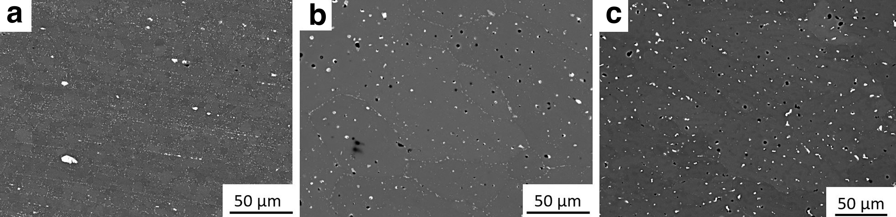
SEM BSE micrographs of
No hot cracks and few gas porosities are observed in all the investigated metallographic specimens underpinning the feasibility as well as the positive influence of our alloy design strategy on the robustness of the deposition process and resulting material properties. In the heat-treated condition (Fig. 1c), the majority of such phases has dissolved during the SHT. Bright phases still visible correspond to dispersoids formed by the elements Cr, Fe, and Si.34,35 During the AA, fine-scaled T-phase precipitates form as has been identified in Refs.30,32 These cannot be resolved by SEM, but their effect can be inferred from the resultant mechanical properties (see the Mechanical Properties section).
Mechanical properties
In Figure 2, the hardness profiles of the as-built material and the heat-treated material are compared. Line profiles are shown with respect to the height of the manufactured sample. Upon deposition the hardness is in the range of ≈105–110 HV0.1 except for the region very close to the substrate, where a somewhat different microstructure forms due to varying cooling conditions and intermixing effects. Through the heat treatment, the hardness is raised to ≈150–155 HV0.1 with an improved homogeneity of the observed values. The differing behavior close to the substrate remains. The pronounced hardening of ∼+50 HV0.1 is related to the previously mentioned formation of nm-scaled T-phase precipitates.
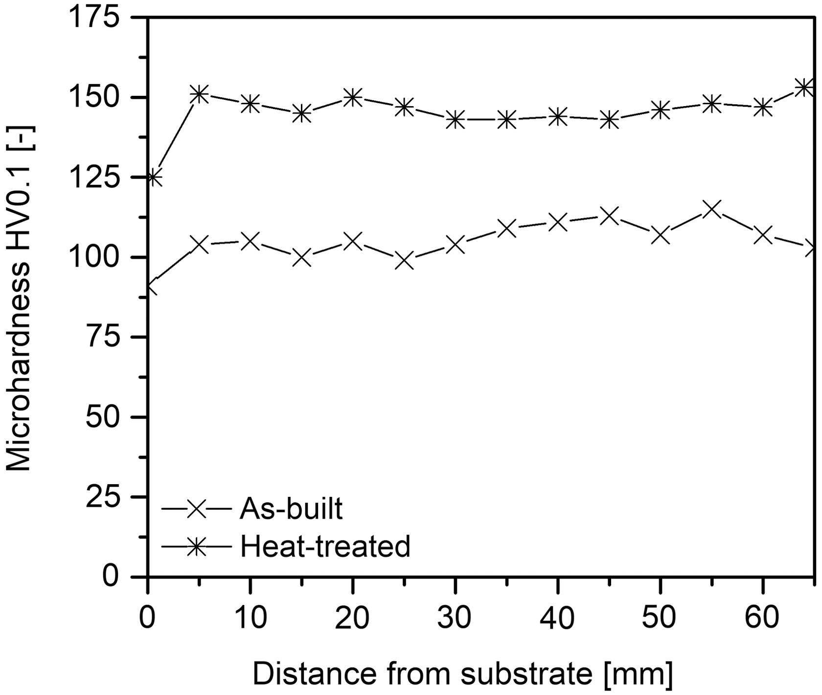
Hardness profiles of the as-built and heat-treated waDED material. In the as-built condition, slight variations with respect to specimen height are discernible. These are less pronounced in the heat-treated condition. Substantial hardening is achieved (+50%) through the heat treatment. In both conditions, lower hardness values are observed in the vicinity of the substrate due to different cooling rates and intermixing effects.
Table 2 summarizes the corresponding tensile testing results of the as-cast and heat-treated materials, in the longitudinal and transversal directions. The hardening through heat treatment is again visible in both yield and ultimate tensile strength. The fracture strain remains anisotropic, which is characteristic for waded-manufactured aluminum alloys. 36 No variations of the specimen location in the coupon were observed and the determined mechanical properties were, thus, concluded to be representative of the alloy processed under the given conditions.
Tensile Testing Results of the Developed AlMgZn Alloy for the Final Wheel Demonstration
Values determined as-cast and heat-treated in both longitudinal and transversal directions.
SD, standard deviation.
Car rim manufacturing using waDED: feasibility demonstration
waDED-specific design modifications
Since car rims are designed for established manufacturing processes (low-pressure die casting, turning, milling, drilling), the geometry selection and adaption for waDED were crucial for a success in manufacturing. The selection of the final geometry, shown left in Figure 3, is based on a three-spoke design with an outer diameter of 520 mm and a height of 230 mm and was provided by partner ALCAR WHEELS GmbH. The geometry was built with the spokes on the build plate (180° vertical rotation compared with Fig. 3) to reduce overhanging structures. The following adaptations of the CAD model were conducted to improve waDED manufacturability.
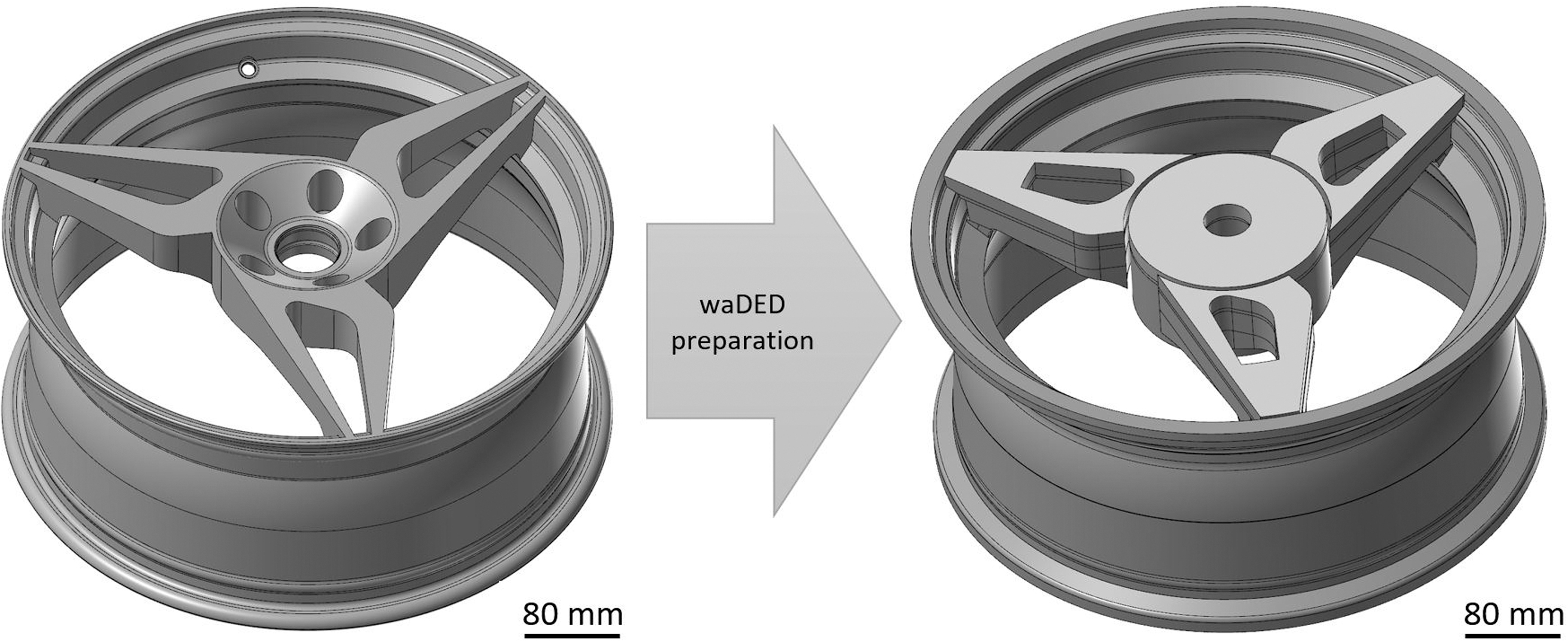
Adaptations made to a car rim model to improve manufacturability for waDED.
Flattening of the top of core and spokes
Removal of the borings
Addition of material for finishing
Separation of main segments with spacing (core, spokes, ring)
Connection of each spoke in the ring area.
waDED path generation
With the aim of efficiently performed trials on the complex sections of the geometry, an excerpt of the ring-spoke intersection was created (Fig. 4). This section is difficult to manufacture since the outer ring has two shallow overhanging sections where it is connected to the spoke. Using the simplified model, shortened calculation times for path studies, and reduced time and material costs for welding trials. The minimal angle between the baseplate and the overhanging ring structure was dictated by the shape of the bead hump of the rim and was 15°. To manufacture such shallow structures, an angled torch is necessary. 37
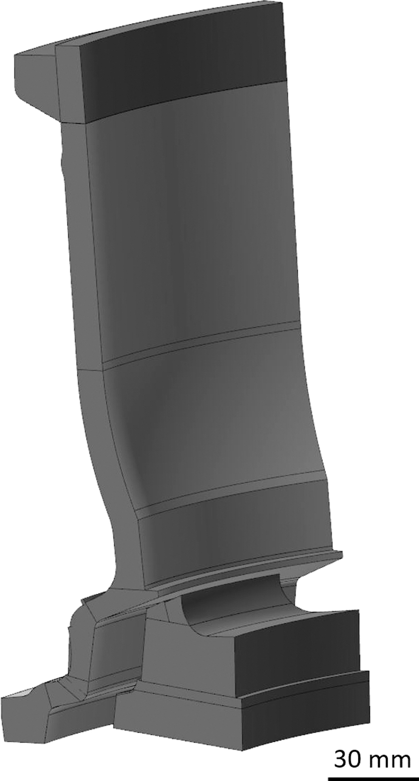
Segment of the transition area between the spoke and rim ring for simplified adjustment and validation of waDED parameters and waDED paths.
Due to the limitations of the LAM module, the outer ring was segmented into smaller solids. Splits were made at the beginning and the end of each overhanging structure (Fig. 4). This enabled the generation of an independent path for each solid. While the vertical ring sections were manufactured with a neutral torch angle, variable torch positions were implemented in the overhanging structures.
Figure 5a shows the angled torch before a spoke. The torch has a tip diameter of 20 mm, which would have collided with the previously manufactured layers of the spoke. Since the LAM module does currently not have an automated collision check and avoidance with already manufactured layers, another solution had to be developed for this purpose. Nevertheless, the existing collision control against solids could be utilized. The spokes were divided in their height at the beginning of each overhanging ring structure. The resulting solids could then be gradually added to the existing manual collision control of the subsequent welding operations.
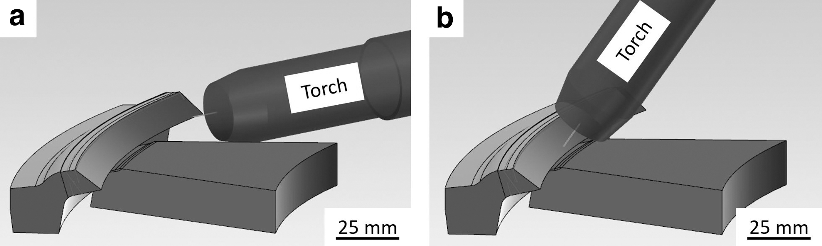
To reduce the effort, the segmentation was only done where the collision control was required. The collision control was further refined by allowing only lateral avoidance. This ensured keeping the lead angle constant during welding resulting in more uniform robot motions. Figure 5b shows the torch position being affected by the implemented collision avoidance to the spoke.
waDED trials of simplified geometry
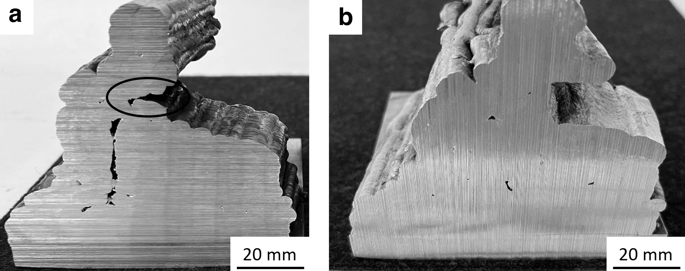
After an initial test in which the welding parameters of Table 3 were determined, the first segment was manufactured (Fig. 6a). The cross section shows a deficient connection between the ring and spoke. To improve the connection, the distance between ring and spoke was gradually reduced in the CAD model from 4.2 to 3.0 mm. In addition, the collision avoidance distance between the torch and workpiece was optimized. This parameter allowed for refinement of the torch angle in the spoke area. Except for the area marked with an ellipse in Figure 6a, those measures resulted in a visually continuous bond of the segments. The connection in the marked area was highly dependent on the layer thickness of the spoke.
Summary of Wire-Arc Directed Energy Deposition Parameters for Initial Welding Trials and Rim Manufacturing
waDED, wire-arc directed energy deposition.
The manufacturing strategy in this area was modified to address this dependency. Instead of alternating the manufacturing of each spoke and ring layer, in this area five ring layers were built in advance followed by filling the gaps of the remaining spoke geometry with the angled torch. The result of the adapted build order is shown in Figure 6b. The connection is, besides minor gaps, uniform throughout the intersection. The main advantage achieved by this strategy is the decoupling from the spoke layer height and the quality of the connection.
In addition, the connection between the two spoke segments, conducted during the design adaptations in the ring area, reduced the number of start and stop points during welding. Since start and stop points lead to a difference in height compared with a steady-state weld seam, 38 it would have been more difficult to achieve a continuous connection between the spokes and the ring.
waDED manufacturing of car rim
For the manufacturing of the car rim, a 10-mm-thick baseplate out of EN AW 5754 material was used. As shown in Figure 7c, the baseplate was mounted with screws on the groove plate of the rotary and tilting table. The screws were placed close to the rim to reduce deformations during welding. In addition, the screw placement was predefined by the grooves and the accessibility after the waDED.

Figure 7a and b shows the welding paths generated for the manufacturing of the three main geometries (core, spokes, and ring). Each layer of the core was manufactured in a continuous spiral starting from the center. The starting point of the spiral differed for each layer by 15 mm to reduce thickness variations caused by start points.
The spokes were manufactured in alternation by radial segments starting at the core to achieve a uniform heat input toward the outside and similar thermal conditions in each spoke. The welding direction was alternated (clockwise and counterclockwise) for each layer of the spokes. The outer ring was manufactured with two different strategies. Up to the height of the spokes, each layer of the ring was manufactured in a continuous spiral starting at the outside. This enhanced the spoke-ring bonding due to the increased part temperature during welding of the intersection. Above the spokes, each layer of the ring consisted of three single paths where at first the outer paths were welded followed by the center line. In addition, the rotary table cooling was activated above the spokes to reduce the interlayer temperature. Both measures were beneficial to achieve a constant layer thickness according to the generated toolpath.
The postprocessing consisted of a stress relieve heat treatment, removal of the baseplate, heat treatment comprising SHT and two-stage AA, as well as the subsequent sandblasting. The finished rim is shown in Figure 8a and b.

Rotational bend test of rim
Besides the main goal of demonstrating the manufacturing capabilities of multitrack waDED, the mechanical properties of the manufactured rim were inspected. For this, the surfaces of the rim relevant for the rotational bend testing were machined to a final dimension, as shown in Figure 8c and d.
The test was aborted after 26,249 cycles due to excessive deflections, which exceeded the specification of the test. Reasons for the early test termination are assumed to be welding defects due to the complex geometry, excessive heating and cooling cycles during manufacturing, or too high values for the maximum bending moment. The influence and further reasons for the test result need to be investigated in more detail in the future.
Assessment of the feasibility of fabricating complex structures by waDED with a new aluminum alloy
The manufacturing of the car rim using a wire from a newly created aluminum alloy was successfully conducted by utilizing commercially available path generation software tools. Simplified trials on the spoke-ring-segment, shown in Figure 4, were necessary to optimize the connection efficiently. The welding parameters for the manufacturing of the rim were largely adopted from the previous, simplified trials.
Due to the long manufacturing time and the need for supervision of the process, overnight breaks were necessary during manufacturing. As preheating of the groove table is not available, welding had to be continued on a cold component. To reduce the negative influence of the cooling period on the spoke-ring connection, the breaks were placed after the completion of a layer. The next layer started at the core, which allowed the rim to preheat before the manufacturing of the intersecting areas between the ring and the spokes. The likely result of this procedure is slightly differing microstructures in these regions of the structure, which may be of lower relevance due to the low quench rate sensitivity of the alloy. 31
Nevertheless, this procedure must be improved for the manufacturing of future components. Preheating the component is necessary to keep a constant interlayer temperature, which is mandatory for a constant weld seam geometry, 39 at least until proper inline process controls are available.
The use of the collision control for automated adaptations of the torch angle to avoid collisions with previously built structures was required for the manufacturing of the rim geometry. Similar studies regarding collision avoidance against predefined structures22,40 or inline process control during skeleton arc additive manufacturing 24 were already subject of studies. With the car rim geometry, the manual segmentation of the solid was possible due to the small number of overhanging areas. Fabrication of parts that require continuous collision control for each layer would not have been sufficient with this approach. Such geometries require an automized collision avoidance with manufactured structures even though this is critical due to the large computational effort on multitrack parts.
Another disadvantage of the used method for collision detection is the dependency on the programmed layer thickness. If the welded geometry diverges from the CAD model, collisions can still occur. Currently there are no automized measures in place to detect and compensate layer thickness deviations in production. One possible solution could be the use of an in situ process control. 41 Alternatively, a process simulation before part manufacturing can reduce the geometrical deviation. 42 Both measures are of high complexity and need excessive computational effort. 43 Therefore, this uncertainty was circumvented in this work by applying an additional safety distance of 5 mm between the torch and geometry in programming and inspecting the clearance during welding.
Considering the economic viability of the manufactured rim, as it was produced in this work, the process was very labor-intensive, due to the high manual programming effort and the need for supervision during manufacturing. Nevertheless, there are multiple measures to improve on that:
Combination of waDED (spokes) with casting (ring) Reduction of excess material to minimal required amount Improvements in process control for unsupervised manufacturing Improvements on collision avoidance with built-up model material.
Especially changing the design into two separate parts would resolve the complexity of the ring-spoke intersection. Path generation and waDED manufacturing would be simplified significantly, which leads to more cost-effective manufacturing. However, it is noted that in the future, the likely use of waDED technologies for the manufacturing of car rims remains in prototyping or low-volume series.
Conclusions
A novel aluminum alloy optimized for the waDED process was presented in this study. To this end, the Mg/Zn ratio was adapted, Cu was omitted, and Cr was added as a structural refiner. The results suggest that the new alloy shows exceptionally good mechanical and technological properties allowing for the fabrication of a complex demonstration object with higher mechanical properties. As an exemplary application, the alloy was used to manufacture a car rim by utilizing commercially available path generation software tools by ModuleWorks GmbH for waDED. By separating the model geometry into multiple solids, the lack of automatic collision control with built-up model material during the path generation could be circumvented. This method allowed to generate an evasive torch movement around the spokes during manufacturing of the rim. The rim shows current capabilities in the production of multitrack waDED parts and suggests improvements such as preheating capabilities for upcoming parts.
Data Availability Statement
The data underlying the present investigations can currently not be shared as it forms part of an ongoing study.
Footnotes
Acknowledgments
Authors' Contributions
F.M.: validation, investigation, data curation, writing—original draft, and visualization; M.S.: methodology, investigation, and writing—review and editing; D.H.: methodology, data curation, and writing—review and editing; T.K.: conceptualization, methodology, validation, formal analysis, investigation, resources, data curation, writing—review and editing, visualization, supervision, project administration, and funding acquisition.
Author Disclosure Statement
The authors declare that they have no known conflicts of interest that could have appeared to influence the work reported in this article.
Funding Information
This research has been funded by the Austrian Federal Ministry for Climate Action, Environment, Energy, Mobility, Innovation and Technology within the framework “Production of the Future” in the project “DEDAluS—Directed Energy Deposition of Aluminum Structures” (grant agreement No. 877340) administered by FFG.