




Abstract
The environmental impact of the construction industry demands sustainable alternatives to traditional concrete production. Microbially induced calcite precipitation (MICP) offers an alternative solution where microbes can produce biocemented structures at a low cost and ambient temperature. This study integrates MICP with nonplanar granular 3D printing methods, overcoming casting limitations such as geometrical constraints and uneven calcification, enabling the creation of thin, porous structures with an increased surface, which is beneficial for biocementation. Our approach combines computational design, microbial techniques, and digital fabrication, presenting biocemented prototypes demonstrating Sporosarcina pasteurii’s ability to achieve natural calcification in printed systems. Materials analysis confirms the microorganisms’ ability to produce more calcite in geometries that provide more surface exposure to the environment, which is a significant advance in large-scale 3D-printed biocemented structures. Moreover, even though 3D printing has already been demonstrated to be a viable means of fabricating small-scale structures capable of MICP, our study presents key steps toward 3D printing MICP-capable structures on a large scale, surpassing the typical small-scale demonstrators below 10 cm to samples above 20 cm in diameter.
Introduction
According to the 2019 World Green Building Council, the construction industry accounts for 39% of global carbon emissions. Of this, 8% of emissions are from concrete production, primarily owing to the burning and resulting chemical decomposition of limestone at 1450°C to produce cement. 1 Recent advances in biofabrication technologies, 2 which can make advanced materials and structures under benign conditions with lower energy inputs, offer attractive alternatives. Many microorganisms produce natural cement in soil and marine environments through microbially induced calcite precipitation (MICP), 3 also known as biocementation. One such organism, Sporosarcina pasteurii (S. pasteurii), can induce calcite formation at room temperature with minimal energy input through urea hydrolysis in the presence of calcium ions. 4
In industry, microbial biocementation is used to fabricate tiles 5 and other architectural components 6 via casting microbes with cementitious materials. Casting, while fast and easy, is constrained by geometrical limitations: thicker solid components, which are efficient to cast, often cause uneven MICP, 7 leading to components with variations in mechanical properties. However, fabricating components with high surface area (SA) and porous forms is more intricate and labor-intensive. Additive manufacturing (AM) technologies provide alternative methods to produce structures with greater geometrical freedom, especially high SA and thin and porous shapes, 8 advantageous for evenly distributed biocementation. Common AM methods for printing with bacteria include extrusion and inkjet 9 processes, which can be slow (undesirable for bioprinting) and require support material to create complex geometries. To this end, we have adopted a suspension print method called nonplanar granular 3D printing (NGP) developed by Darweesh et al. (2023) 10 that combines a granular support bed with the suspension printing of S. pasteurii laden binders to create granular prints embedded with bacteria that then biocement and harden upon incubation.
Previous research on 3D printing with MICP-capable S. pasteurii includes studies on printing artificial coral 11 and producing homogenous biocementation in 3D-printed structures via different material distribution strategies. 12 These approaches, however, have hardware constraints and are limited in scale. This study hypothesizes that we can overcome such limitations by using our integrative approach that combines computational design, microbial techniques, and a unique digital fabrication process to produce large-scale 3D printing biomineralized structures that can eventually be used in construction.
We present a series of biocemented prototypes that showcase our biofabrication workflow (Fig. 1), which marries the MICP activity of S. pasteurii with the NGP process that creates a high SA, thin member lattice structure that can naturally calcify. We show the capacity of bacteria to biofabricate a permanent binder through a comprehensive material analysis of the structures. We also show that by producing high SA lattice structures, we can obtain a higher degree of calcification than structures of the same material quantity, but with a lower surface area to volume (SA/V) ratio. Our results are the largest 3D-printed MICP structures to date and expand the field for possible applications of 3D-printed biocemented elements in design and architecture.
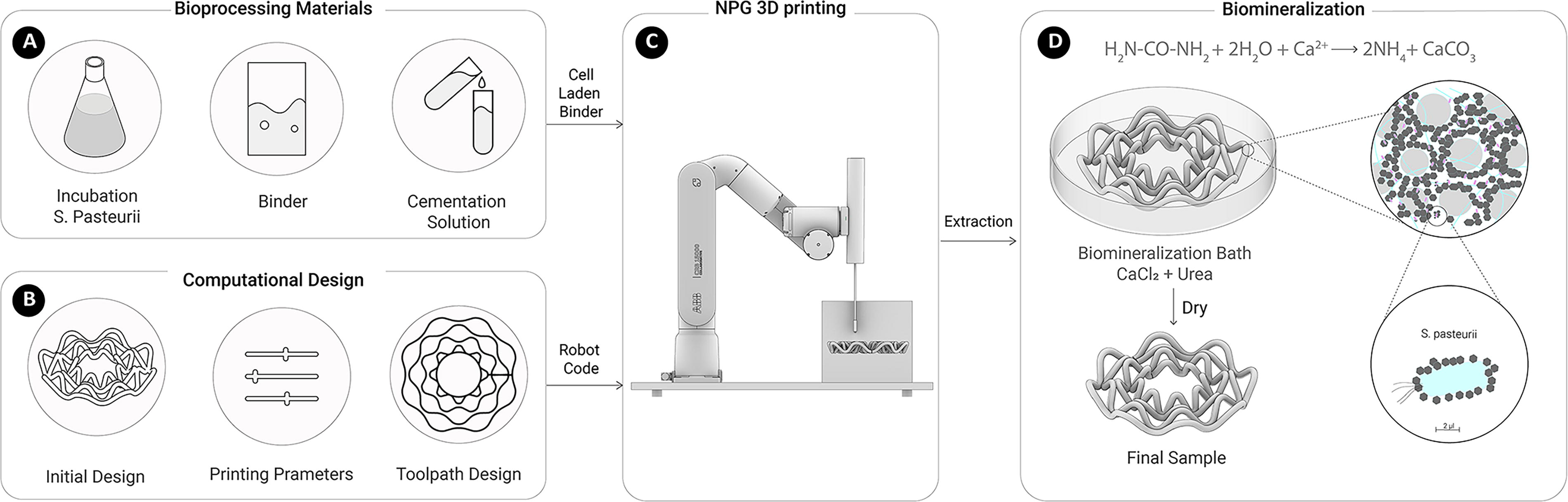
Fabrication workflow of MICP-capable materials.
MICP
Microbially induced calcium carbonate precipitation is a metabolic process of biomineralizing organisms forming biominerals, such as calcium carbonate (CaCO3). 13 These biominerals help seal cracks in concrete, 14 consolidate soils, 4 decrease the permeability of concrete, 15 and increase compressive strength. 16 The most common MICP metabolic pathways are urea degradation, denitrification, sulfate reduction, and photosynthesis. This study explores the ureolytic pathway, particularly with S. pasteurii, a well-studied microorganism. These bacteria produce the enzyme urease, which degrades urea and forms an extracellular alkaline environment that induces CaCO3 precipitation along the cell membrane (see Fig. 1D). 17 The precipitation develops into calcite crystals that bind aggregates and harden material at a much lower energy demand than industrial processes.
3D printing materials capable of MICP
Our suspension printer is an adapted version of a nonplanar granular (NPG) printer developed and described by Darweesh et al. 10 The set-up consists of a six-axis robotic arm navigating a slender nozzle through coarse granular material, injecting liquid binder to bond particles into a 3D form. NPG printing offers several notable advantages for printing living material: it is a faster printing process, it has expanded geometrical freedom (compared with extrusion processes), and the embedded nature of the process reduces the risk of delamination between layers.10,18 It also allows for using viscous water-based binders like hydrogels and facilitates the easy incorporation of living cells into those binders. This holds a particular value for MICP, as it allows for the precise placement of cells within the granular substrate (i.e., sand, soil) that MICP usually works on. The support bed also allows complex geometries, including ones with a high SA/V ratio, 19 which is beneficial for biocementation, as many MICP processes occur at the interface between air and solid form. Hence, maximizing this surface increases the space for biological activity. 19 Additionally, a high SA/V ratio ensures that nutrients and cementation solution have enough interface to penetrate the entire structure during the biocementation process, facilitating rapid calcite formation and the natural stabilization of the structure without the need for industrial cement or petrochemical binders. Finally, the method uses a simple, easy-to-clean hardware set-up, making it a promising option for the scale-up of printing microbially biocemented material.
For this study, we evaluate whether 3D printing a high SA, thin member lattice geometry would result in substantially more MICP than compared with a solid geometry of the same material quantity. We printed a set of circular lattices and cylinders with the same amount of binder and granular material to see the effect of geometry on bacterial activity and MICP processes. After incubation, we examined the biocemented cross-sections via scanning electron microscope (SEM) and energy-dispersive X-ray analysis (EDAX) to assess the depth penetration and distribution of MICP throughout the structure. We quantified the amount of CaCO3 precipitation in the different samples by various methods. Finally, we use the process to 3D print a scaled-up lattice capable of MICP.
Materials and Methods
Bacteria preparation
S. pasteurii (DSM33) was obtained from the German Collection of Microorganisms and Cell Culture by GmbH (DSMZ, Braunschweig). The bacteria were cultured in liquid nutrient media (Supplementary Data S1). The cultures were incubated at 30°C in Erlenmeyer flasks on a shaker plate with constant shaking (250 rpm). The optical density of the bacterial suspension at 600 nm (OD600) was measured using a UV-visible light spectrophotometer (Jenway 7305 UV VIS) to monitor bacterial culture growth. All experiments were performed using bacterial cultures in their logarithmic growth phase. Liquid cultures were centrifuged for 15 min at 4500 RCF (Eppendorf Centrifuge 5430R). The supernatant was removed, and the remaining bacterial pellet was resuspended into the print binder; the mixture was made homogenous with a cell OD600 ∼1.0. The binder is a biocompatible, loose network hydrogel chosen to provide adequate structural support and nutrient transport without adverse effects on bacterial activity. The quantity of live bacteria culture added was grown at 2.5 times the volume of total binder used, at OD = 1. This concentration ensures sufficient microbial activity for calcite precipitation and homogeneous distribution of cells through the structure. The material was then used for 3D printing or in the cast cylinder samples described below.
Samples preparation
Our print samples were made in a granular bed of glass sand, ∅ = 0.1–0.2 mm (Sandstrahlen PLUS GmbH, Switzerland) and bound with a biocompatible binder. To evaluate the effectiveness of biomineralization within the proposed material mixture, we prepared cylindrical cast samples of the same materials for unconfined compression strength (UCS) testing. Three biotic and abiotic cylinder piles were fabricated, ∅ = 20 mm, h = 40 mm, following the DIN 18136 standards for a diameter-to-height ratio of 1:2 for UCS test specimens. The diameter of the piles was small enough to be comparable with the test print diameters but thick enough to prevent buckling effects. The binder was premixed into the sand at a binder-to-sand percentage of ∼27% (w/w) to match the ratio proportion established by a series of print extrusion tests at various print speeds (see Table 1). The extrusion ratio was measured by comparing the mass of identical print paths of binder only with binder + sand. The wet sand–binder mixture was then cast by compacting it in 5 mm high layers within a cylindrical formwork and left to set.
Print Parameters to Predict Print Width
Each pile was placed in a cementation solution (Supplementary Data S1) inside a 50 mL beaker on a raised perforated tray (to allow solution penetration on the underside of the pile). The cylinders were incubated at 30°C at a relative humidity of 50% for 4 days, with daily cementation solution changes as suggested by Hirsch et al. 11 After incubation, each sample was rinsed with deionized water and dried at 60°C until a consistent dry mass was achieved. Before compression testing, minor irregularities on the top and bottom compression surfaces were sanded flat.
Hardware
All prototypes were printed with a six-axis robotic arm (ABB, GoFa CRB 15000). The arm was outfitted with a pneumatic extrusion cartridge (Nordson 7012436) that empties through a custom stainless-steel nozzle, ∅ = 0.4 mm. Extrusion pressure was regulated via manual pressure regulators (FESTO LRP-1/8-6 and SMC-AC30 KKV209) and controlled via I/O switches on the GoFa. The nozzle moves through and injects liquid binder into a build tank of the granular substrate, in this case, glass sand (Fig. 1C). Depending on the size of the print samples, different build tanks were used, ranging from 14 × 14 × 8 cm (W × D × H) to 30 × 30 × 50 cm.
Digital fabrication framework
The computational forms were designed using custom scripts built in the CAD software Rhinoceros 3D (McNeel & Associates) and the visual programming environment Grasshopper 3D. In suspension printing processes, form generation is closely linked with toolpath planning, as the form is generally defined via polylines or curves rather than a planarly sliced volume; these forms also typically favor a continuous toolpath strategy.18,20 This strategy lends itself particularly well to lattice geometries, which are also favored for their high SA/V ratio, which is advantageous for MICP.
Our platform uses a Python-based robotic motion planning software for robot joint movements, collision and singularity checks, developed by Pok Yin Victor Leung using methods described in his thesis, Leung 21 , and in Huang et al. 22 which plans robot joint movements and performs collision and singularity checks using customized Pybullet, Compas Fab, and Nonplanar Printing libraries. Toolpaths and extruder control commands are transmitted to the ABB via Compas RRC; the computation design workflow is iterative, as described in Figure 2.
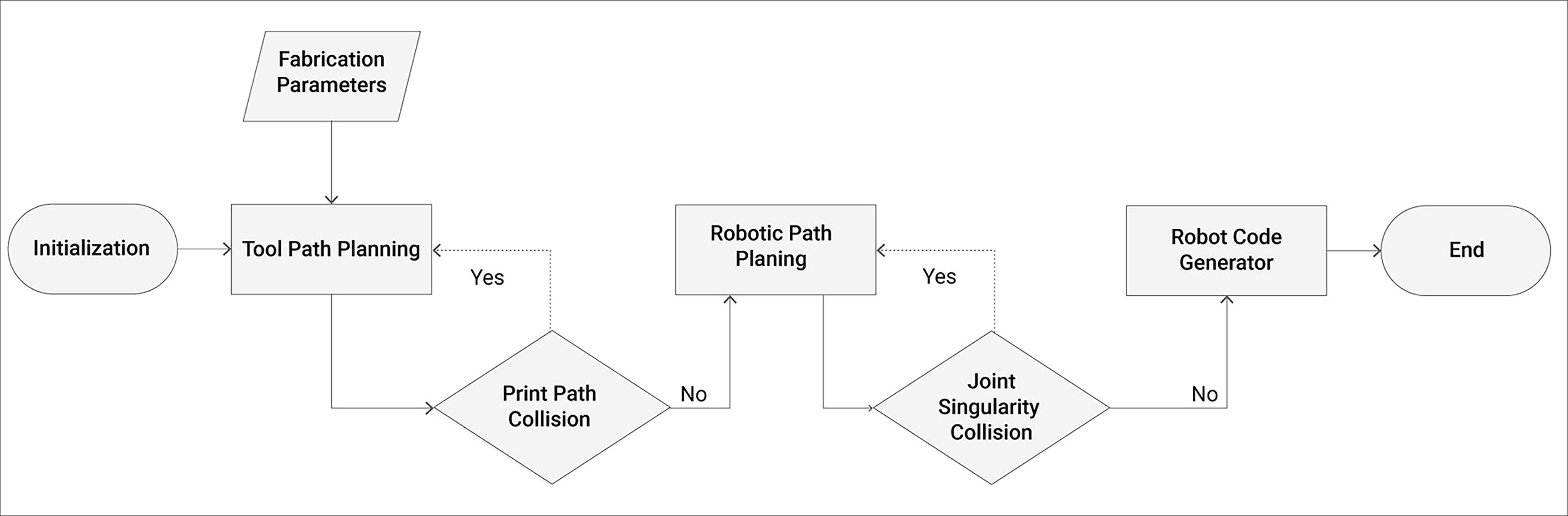
Computational design workflow chart for NGP 3D printing; design and fabrication parameters are input to generate the main robot program in an iterative process.
Printing parameters
Common to many other AM processes, print parameters such as nozzle diameter, print speed, extrusion pressure, bonding distance, and material viscosity were used to control the print lines’ width and determine the print’s possible resolution. 23 Additionally, toolpath orientation (Fig. 3D) and sequencing are critical in this system, as suspension printing typically does not allow the tool to pass over the same position twice since this would disturb print lines already extruded. This means path intersections need to be separated by an optimal bonding distance to meet but not disturb already extruded lines (Fig. 3C). Also because the print process is done inside a granular bed, toolpaths printed deeper in the bed (lower z-height) typically have a different width than toolpaths near the surface of the granular bed, depending on the viscosity of the binder (Fig. 3A). With our current set-up, we also obtain a bean-shaped cross-section for our toolpath (Fig. 3B), which further increases the SA of our structures.
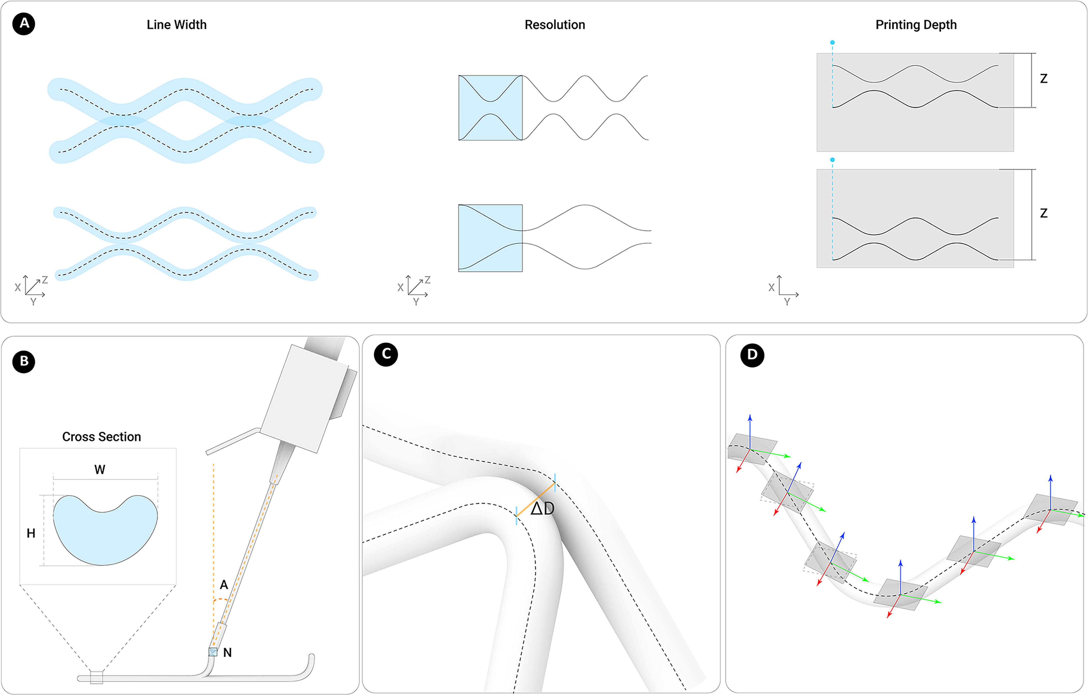
Spatial structure design and correlated toolpath design parameters.
We performed a series of abiotic 10 cm long print path tests at eight different print speeds under a constant extrusion pressure of 2.0 bar to see how we could control line width and resolution (Table 1). With our current materials, the finest line size that remains intact after extraction is 8.94 mm wide × 5.90 mm high. Based on these initial tests, we used a print speed of 15 mm/s at an extrusion pressure of 2.0 bar for average line widths of 10 mm for our subsequent tests.
To explore the capabilities and constraints of our print set-up, we designed and printed three forms with distinct toolpath strategies: a cylinder drawn in a continuous spiral toolpath and a quadrilateral hexahedron (QH) lattice drawn in short-segmented lines in horizontal, vertical, and diagonal directions, and a circular wave polyline (CWP) lattice drawn in semicontinuous curves (Table 2). The continuous toolpath cylinder was the easiest and cleanest to print, provided the vertical overlap distance was correctly tuned between layers. The QH lattice presented challenges, including variations in strut diameter, overextrusion at vertices, and underextrusion in other areas. The CWP lattice showed promising results, mitigating intersection collisions and variability and enabling efficient fabrication of MICP-compatible lattice structures. Also significant is the fast print time on each of these samples (between 2 and 4 min per print, see Table 2), which would be advantageous for bioprinting by minimizing the exposure time of living cells to print conditions.
Comparison of 3D-Printed Granular Objects

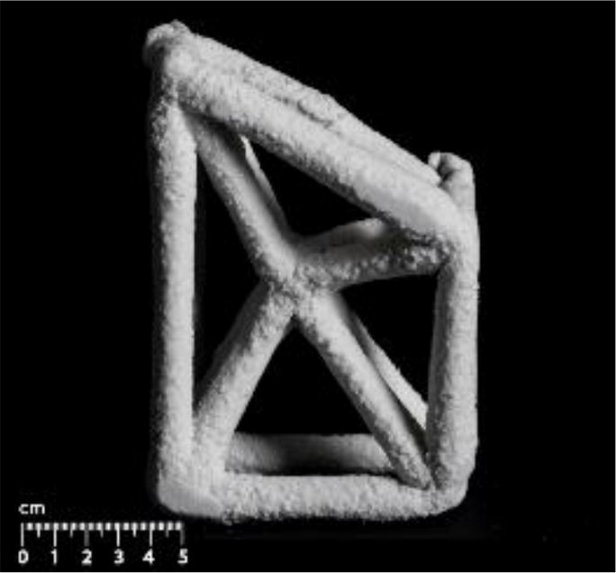

CWP, circular wave polyline; QH, quadrilateral hexahedron.
Biofabrication
We 3D printed identical sets of different geometries of abiotic (nonliving) control and biotic prints capable of MICP. For the abiotic, only the biocompatible binder was extruded into the granular bed of glass sand; for the biotic samples, the binder was first premixed with the S. pasteurii cell pellet, as described above. The binder was loaded into 360 mL cartridges that pneumatically emptied into the print nozzle. Extrusion pressure ranged between 1.9 and 2.3 bar at a print speed of 15 mm/s.
SA test
For our SA/V comparison, we printed a set of four prints consisting of abiotic and biotic versions of a six-node CWP and a solid disc made of concentric circle polylines (CCPs) (see Fig. 5B). Both forms had identical toolpath lengths (2.610 m). Extrusion pressure was fixed at 1.9 bar at a print speed of 15 mm/s for the four prints to ensure the same amount of extruded binder in all the tests (56.167 g).
Once the prints had been set, they were removed from the granular bed and weighed. Following the protocol with the compression samples, the four comparison prints were each immersed in 450 mL of cementation solution (Supplementary Data S1). The prints were incubated at 30°C at a relative humidity of 50% for 4 days, with daily cementation solution changes. After incubation, the samples were rinsed with deionized water, weighed, and dried for 7 days at 60°C until a consistent dry mass was achieved.
Quantification and analysis of MICP
Multiple established methods were used to verify that the biotic samples were biologically active and to quantify the amount of calcium removal from the cementation solutions and the structures’ CaCO3 content (CCC). From the compression piles, 10 mL from each day’s “used” cementation solution was sampled for titration 24 (Supplementary Data S2) to quantify the calcium ion concentration remaining after each day of incubation, indicating how much was taken up by the samples. Gravimetric acid washing, as explained by Harran et al. (2022), 25 was performed on both the compression piles and the biotic CWP and CCP prints (Supplementary Table S1). For the SA test described above, we cut a 1/6th pie slice from dry 3D-printed biotic geometries (Fig. 5B). The slice samples were crushed, weighed, and washed in 1 M HCl to remove all calcite produced. The washed remainder was dried and weighed again to quantify the CCC percentage. SEM and EDAX were used for detailed examinations of the structural morphology of the CaCO3 precipitate and to visualize the degree and distribution of MICP. Finally, 3D scanning (Creaforma Go! SCAN 50) was done to visualize biomineralization’s effect on the prints’ thickness.
Results
Effect of MICP on the cast cylinders
The cast cylinders’ UCS was assessed by applying a path-controlled axial load at a rate of 0.4 mm/min (Shimadzu AGS-X Table-TOP precision universal tester). Three abiotic cylinders were compared with three biotic cylinders to investigate the potential increase in compressive strength through biomineralization. Gravimetric analysis shows that while the abiotic piles did not indicate CaCo3 precipitation with 0.286% CCC, in contrast, the biotic piles had 10.22% CCC (Supplementary Table S1).
A mean UCS = 695 kPa was observed for the abiotic specimens through a typical shear failure pattern (Fig. 4C). For the biotic samples that underwent MICP, a maximum UCS of up to 1210 kPa was achieved, representing a 74% increase compared with the mean abiotic UCS. However, for the biotic samples, there is a significantly increased standard deviation of compressive strength (see Fig. 4B). After incubation, we noted surface-level mineralization of the cylinders rather than homogeneous calcification across the 20 mm ∅ cross-section. This outcome can most likely be attributed to the diffusion of cement agents through the pillars by immersion. Previous studies12,26,27 achieved more considerable penetration depths of calcification using a percolation method for incubation, resulting in significantly higher UCS values. This surface-level mineralization results in a stiff and rigid external calcified shell around the biotic cylinders, ∼2 mm (+/− 0.5 mm) thick. During compression tests, the loads were significantly borne by the stiff outer shell, leading to progress in axial tensile splitting in the biocemented outer crust (see Fig. 4C). The stepwise cracking of the shell before total failure can also be seen in the local spikes of the stress–strain curve (see Fig. 4A). Thus, the limited penetration depth of calcification is a constraining factor in our material process when trying to achieve maximum load-bearing capacity in 3D-printed biomineralized structures. Therefore, aiming for smaller diameters in the printed toolpaths is required to achieve more uniformly distributed biomineralization of the cross-section. The NPG printing process could capitalize on this requirement, efficiently producing porous, thin member, and lattice structures facilitating enhanced cementation depth throughout the samples.

Assessment of MICP piles.

SA geometries.
Effect of geometry on MICP in 3D-printed samples
As outlined above, abiotic and biotic versions of two geometries, the CCP disc and the CWP lattice, were 3D printed using the same amount of material for each print. The four samples were incubated in a cementation solution under the same conditions. After incubation, the biotic samples showed physically visible hardening, whitening (with large calcite occlusions), and weight gain compared with the abiotic structures (Fig. 5). Both biotic prints gained mass when wet, unlike the abiotic structures, which stayed roughly the same or lost weight. This mass difference becomes more pronounced upon 7 days of drying, where the biotic samples are substantially heavier than abiotic (Fig. 6E). Comparison of the 3D scans after incubation also confirms that the biotic structures are thicker in the case of the CCP disc or have developed more SA in the case of the CWP lattice compared with their abiotic counterparts (Fig. 7), indicating biocementation build up on the outer surface of the biotic prints.

Material analysis of 3D-printed structures.

Cross-sections of 3D models.
Furthermore, the biotic versions of the two different geometries (CCP disc vs. CWP lattice) showed diverse weight gain and hardening despite starting with similar amounts of material (288 and 289 g, respectively). Gravimetric analysis of the 1/6 slices shows that at 4.76 g calcite mass (1.96%), the CCP disc has a substantially lower calcite content (CCC) than the CWP lattice at 12.91 g (4.96%) (Table 3). This 2.53× increase in calcite mass in the CWP geometry corresponds roughly with the 2.34× increase in SA of the CWP lattice over the CCP disc geometry, allowing for more of the S. pasteurii to perform MICP in this lattice form actively.
The Effect of Surface Area in Microbially Induced Calcite Precipitation
CCC, CaCO3 content; CWP, circular wave polyline; CCP, concentric circle polyline.
In addition, the samples for the SEM (Fig. 6A–D) were taken from bean-shaped cross-sections of the CWP lattice struts, approximately 9 mm wide × 5 mm high. The biotic sample shows a homogeneous distribution of the precipitate across the cross-section, indicating that the cementation solution had effectively infiltrated the print (Supplementary Fig. S1). Additionally, the precipitate shows the structural morphology of calcite crystals that span between glass granules and, after 4 days of mineralization, appear to fuse and form mineral bridges between them, aligning with previous studies.4,11 These results indicate that through MICP, the active bacteria can structurally bind the granular material permanently.
Upscaling NPG 3DP for biomineralized structures
To demonstrate the first attempts at scaling up the process as a step toward fabricating large-scale components, we printed abiotic and biotic versions of a larger CWP lattice based on the results discussed in the previous sections, using an eight-node topology, ∅ = 210 mm, height = 67 mm, and SA = 1997.1 cm2 (Fig. 8). The prints were incubated at 30°C at 50% relative humidity in 1.7 L of cementation solution for 6 days, with media being changed every 2 days. After incubation, the prints were removed from the solution and dried at room temperature for 7 days for qualitative comparison. Like the smaller prints, the biotic print shows visible hardening and whitening compared with the abiotic sample. Also noticeable in the dry samples is that the biotic print remains rigid and sturdy after a month, while the abiotic has softened and is easily damaged.

Demonstrator.
To our knowledge, this is the largest 3D-printed structure capable of MICP in publication. The increased size necessitates a larger build tank, ∅ = 260 mm, and more material preparation. Cell culture volume had to be increased to maintain the same cell concentration in the binder and similar levels of biological activity. The incubation tank also needs to be enlarged and more cementation solution is required, with a more extended incubation period and more media changes. It is important to note that while these changes may seem trivial in typical print conditions, our current workflow is done in a clean environment with sterile materials and equipment, leading to significant investments in labor and materials with scale-up.
Discussion
Tectonic integration of MICP via AM
This study introduces an integrated approach combining MICP processes with NPG printing to create customized biologically cemented spatial structures. Unlike previous MICP-based 3D prints limited to centimeter-scale dimensions,11,12,28 our method allows for larger-scale fabrication, demonstrating the scalability of our approach for architecturally relevant biocemented elements. Furthermore, by reinforcing the structures with bacteria in a biocompatible water-based binder, we depart from prior studies in NGP printing reliant on petrochemical binders 18 or cement. 29 Also, our approach capitalizes on the metabolic activity of S. pasteurii, which facilitates the consolidation of mineral structures with minimal energy input and contributes to the sustainability and scalability of potential applications in the construction industry.
Compared with other manufacturing techniques for MICP, such as selective powder deposition 12 or casting,7,30 our nonplanar 3D printing method offers several advantages. By leveraging nonplanar designs, we tailored stable, open-lattice structures to receive cementation agents evenly from all directions, ensuring uniform distribution of CaCO3 throughout the printed component, as demonstrated by SEM scans of the printed cross-sections. Additionally, the hardware can be scaled up relatively quickly by increasing the tank size and the reach of the robot arm to produce larger biocemented structures. However, it would be essential to consider the resulting increase in the prints’ self-weight to ensure they do not collapse during extraction before cementation can occur.
Moreover, our study explored the influence of geometry on bacterial activity and biomineralization by fabricating a series of nonplanar biocemented structures. Our results demonstrate that increased SA significantly enhances calcite formation up to 2.5 times more effectively, underscoring the importance of design considerations in enhancing MICP efficiency. Furthermore, while our experiments focused on the geometric effects, future research avenues may further explore optimizing bacterial concentrations and cementation agents to augment calcification rates.
Future research should focus on optimizing mechanical performance through geometric adjustments and material processes. 25 This optimization entails refining material characterization and developing tools for simulating structural behavior, integrating material properties into the design workflow. Moreover, introducing a more precise binder dispenser could help control flow rate and variation in line dimensions to improve the structures’ print fidelity and the system’s reliability compared with the digital model.
Given the system’s versatility, exploring various granulate material types could enhance the biocementation process and resultant material strength. Furthermore, investigating alternative MICP-capable organisms, which could also benefit from the fabrication process, such as photosynthetic organisms, holds promise for developing low-embodied energy structures capable of sequestering and storing CO2, as supported by emerging studies in the field.31–33
Although our research demonstrates MICP across different scales, incorporating biomineralized 3D-printed components into architecture will require further study. Given the observed compressive strength, it is possible to use this system in nonload-bearing applications, such as facades and partitions, where the large SA presented by these components could offer advantages for incorporating other species and enhancing biodiversity in urban environments.
Conclusions
We showcase the capacity of the NPG bioprinting process to produce the most significant 3D-printed microbially biocemented structure to date. We also demonstrate how geometry influences the effectiveness and distribution of microbial activity. To do this, we have developed a computational and design process to incorporate specific biological functionality, in this case, MICP, into a design and fabrication workflow. As part of our workflow, we present NPG print parameters that can be tuned to create biotic structures in geometries that exhibit improved mechanical strength and durability compared with components and geometries that did not need this fabrication process. We also quantify the amount of calcite produced to assess the quality of the tectonic interface created by the bacteria on the inorganic scaffold.
Our study integrates a multidisciplinary approach that connects research across microbiology, digital design, and AM to achieve alternative construction materials and practices. We can combine the established capabilities of S. pasteurii to mineralize inorganic porous scaffolds with a novel NPG printing process, which offers enough design freedom to create geometries favorable for MICP. Our approach demonstrates the possibility of an alternative fabrication method that harnesses biology’s ability to naturally self-assemble consolidated structures and whose effectiveness can be augmented through a digital design and fabrication workflow. This approach has implications for using 3D printing in biofabrication to create radically different types of building materials while potentially reducing construction industry carbon emissions in their production. The tectonic integration of living organisms capable of MICP into 3D-printed structures has the potential to create more sustainable lines of production of architectural elements, where the use of biotechnology with an integrated design workflow leaves room for the formation of advanced, biologically active, and adaptable components.
Footnotes
Acknowledgments
We would like to warmly thank the following collaborators: Barrak Darweesh and Prof. Simon Schleicher (Robotic Fabrication Lab, University of California, Berkeley) for their print hardware contributions; Dr. Victor Leung (Gramazio Kohler Research, ETH Zürich) and Dr. Yijiang Huang (Computational Robotics Lab, ETH Zürich) for their path planning libraries; Alessandro Dutto, Diego Giovanoli, and Moritz Garger (Complex Materials Group, DMATL, ETH Zürich) for material assistance; Tobias Hartmann and Phillip Fleischmann (Robotic Fabrication Lab, ETH Zürich) for hardware assistance; MAS DFab program (ITA, DARCH, ETH Zürich).
Authors’ Contributions
K.A.P.: Conceptualization, data curation, formal analysis, investigation, methodology, software, visualization, writing—original draft, writing—review and editing. A.S.L.: Conceptualization, data curation, formal analysis, investigation, methodology, hardware, software, writing—original draft, writing—review and editing. N.M.: Data curation, formal analysis, investigation, software, visualization. G.B.: Data curation, formal analysis, investigation, software, writing—review and editing. B.D.: Supervision, writing—review and editing.
Author Disclosure Statement
All authors declare that they have no competing interests.
Funding Information
This work was done within the framework of the ALIVE initiative (Advanced Engineering with Living Materials) and funded by the SFA-AM program (Strategic Focus Area – Advanced Manufacturing) and the ITA (Institute of Technology and Architecture) A&T (Architecture & Technology) Doctoral Fellowship.

References
Supplementary Material
Please find the following supplemental material available below.
For Open Access articles published under a Creative Commons License, all supplemental material carries the same license as the article it is associated with.
For non-Open Access articles published, all supplemental material carries a non-exclusive license, and permission requests for re-use of supplemental material or any part of supplemental material shall be sent directly to the copyright owner as specified in the copyright notice associated with the article.
