
Abstract
In contrast to traditional polymer fabrication, additive manufacturing eliminates the need for tooling and reduces production lead times, making it ideal for batch production. Specifically, fused filament fabrication (FFF) is notable for its liquid and powder-free process, which is suitable for vacuum and low-gravity conditions. However, the anisotropic strength of FFF parts limits their use. This research presents a methodical approach to improve the mechanical strength of 3D-printed carbon fiber (CF)-reinforced polyether ether ketone (PEEK) components, aiming for improved mechanical strength by applying in-process laser heating. CF PEEK is selected for its exceptional strength, durability, and heat resistance. The core of this laser technique is to increase the interface temperature, slowing down the cooling phase, which promotes polymer chain movement and entanglement, leading to enhanced mechanical properties. This method significantly boosts the mechanical strength of 3D-printed PEEK in the build direction from 9.3 MPa to 60.5 MPa, with the strain increasing by 150%. Additionally, there are notable differences in fracture behavior: the control sample fractures at the interlayer interface, while the laser-treated sample fractures within the layer. Adopting this advanced approach could address the current limitations of FFF 3D printing in manufacturing and enable FFF to serve fields that require mechanical strength and small-batch production. This technique has the potential to extend polymer additive manufacturing to fields requiring high-temperature, high-strength composites, such as in-space manufacturing/assembly, small-batch production for aerospace parts, medical components, and prototypes.
Introduction
Additive manufacturing, also referred to as 3D printing, is a process that constructs 3D objects layer by layer based on a digital 3D model.1–3 Fused filament fabrication (FFF) stands out among various additive manufacturing techniques for its compatibility with thermoplastic materials. Unlike traditional thermoplastic polymer manufacturing methods, such as injection molding, which entail the use of costly molds ranging from several thousand to tens of thousands of dollars and entail extended lead times spanning weeks to months, contingent upon complexity and precision requirements, FFF offers the distinct advantage of producing parts at significantly reduced costs and lead times, particularly suitable for small-batch production.4–6 Additionally, FFF is favored for its accessibility and flexibility in terms of both the manufacturing process and the range of materials utilized.7–12 Offering numerous benefits, including the capacity to work with a diverse range of printable materials, print single parts with multiple materials within the same build volume,13–15 create objects of various sizes, 4 and fabricate components compatible with biomedical applications,16,17 FFF presents a versatile manufacturing solution. Moreover, it delivers substantial cost savings for small-batch production, particularly in aerospace applications, by obviating the need for tooling and diminishing lead times. 18 Nonetheless, it is essential to note that parts manufactured via FFF typically demonstrate relatively low mechanical strength, particularly along the build direction. 19
The anisotropic properties observed in parts manufactured via FFF stem from the fundamental characteristics of the extrusion-based process. In this method, the filament feedstock is pushed through a nozzle by rollers and deposited on a build plate or the previously deposited materials. Two conceptual frameworks, termed the “nozzle flow” and “90° turn” models, have been employed to understand the mechanics and rheological characteristics of the extruded material,20–22 as depicted in Figure 1. These models describe the thermomechanical mechanisms underlying the process. According to them, during deposition, polymer chains experience considerable stretching and disentanglement, especially in regions close to the track’s surface.22,23 To ensure isotropic properties in the printed part, it is crucial for polymer chains on the track surface and at track interfaces to undergo complete reptation and relaxation processes, influenced by both time and temperature.22,24 Note that due to the extrusion process, infills are mostly aligned along the in-plane direction (along the deposited track, left to right in Fig. 1).
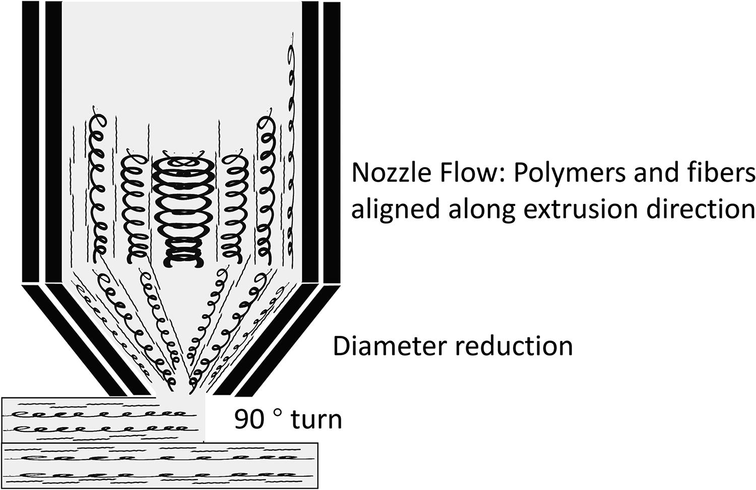
Schematic diagram of the material flow during deposition in FFF. FFF, fused filament fabrication.
In practical terms, when given sufficient time and adequately high temperatures, polymer chains have the potential to undergo complete relaxation and entanglement, leading to microstructures resembling those observed in parts produced through conventional methods like injection molding. However, during the deposition process, the polymer extruded from the nozzle and deposited either on or alongside a previously laid track experiences lower temperatures due to the time it takes for the nozzle to traverse its designated path. This results in insufficient reptation and relaxation.19,22,23 Consequently, parts produced via FFF exhibit anisotropic mechanical strength, with the weakest directions typically oriented perpendicular to the interfaces between layers and tracks.
Various efforts have been performed to solve the weak mechanical strength issue of FFF-printed parts. Many of these endeavors have concentrated on enhancing the interlayer bonding strength by manipulating printing parameters such as nozzle temperature,25–28 build plate temperature,29,30 print speed,28,31 layer thickness,32–35 and raster strategy.36,37 Nevertheless, the ability to optimize these printing parameters is limited by the fundamental physics of the FFF technique, containing polymer stretching and disentanglement from the shear flow in extrusion, along with the insufficient temperature at the interlayer interface and intertrack interface, which obstructs reptation and relaxation.
Post-processing techniques like heat treatment have also been investigated for the improvement of mechanical strength,38,39 as well as using laser to scan the entire layer during printing before depositing new layers. 40 In-process techniques, including in-process pre-deposition laser heating and ultrasonic vibrations, have successfully enhanced bonding strength at the interfaces between layers19,23,41–44 with homogeneous materials only. Many efforts have been made to improve the mechanical properties of carbon fiber (CF)–reinforced polymer materials,45–50 and continuous fiber-reinforced polymer materials.51,52 No prior research has been reported on improving the mechanical strength of CF-reinforced high-temperature polymer with the usage of in-process pre-deposition heating technology. Hence, the influence of this procedure on fiber-reinforced polymer material is uncertain, as fibers might exhibit distinct behavior within the polymer matrix’s liquid phase during extrusion and deposition, potentially influenced differently by the cooling process. It is essential to comprehend the repercussions of these fibers on the mechanical characteristics of the end product, considering the intricacies of fiber dynamics in the liquid phase.
This research explores how in-process laser pre-deposition heating technology impacts the mechanical properties of CF-reinforced polyether ether ketone (PEEK). The laser-assisted technique is developed and implemented to a commercial 3D printer, and the tensile strength and strain along the build direction of both laser-treated and control samples are analyzed. Disparities in fracture surface and stress-strain curves among the samples are assessed and deliberated upon.
Materials and Methods
3D-printing apparatus
A customized laser-assisted 3D-printing apparatus is built on the platform of a commercial FFF 3D printer (Funmat HT, Intamsys, China). This platform has a closed chamber with ambient heating, therefore enabling the fabrication of high-temperature polymers like PEEK and Ultem. A schematic diagram is shown in Figure 2 for the apparatus with laser components. In this setup, a CO2 laser (Synrad 48-1KAN, Mukilteo, USA) with a continuous wave is used as the radiation heating source. A customized splitter setup on an optical platform with multiple triangular gold mirrors and laser couple is built to allow four uniform power outputs. The laser then passes through an optical fiber into the 3D printer and focuses on a spot that is an oval shape (4 mm by 2.5 mm) close to the nozzle end using a laser collimator and a gold mirror. The laser collimator and gold mirror for reflection are installed on a customized bracket-shape hot end to maintain the position of the laser spot during the travel of the extruder head. With this setup, the four laser beams are capable of covering all directions for in-process pre-deposition heating regardless of the nozzle moving direction.

Schematic diagram of the 3D-printing apparatus.
In this study, the goal is to investigate the effect of laser preheating on the bonding strength of CF-reinforced material. The sample prepared is single-track one direction. Therefore, only one laser (shown in Fig. 2) can be used for preheating. The other three laser spots will result in postheating and side heating of lower layers that may induce errors in the experiment. Therefore, only one laser is turned on in this work.
Sample preparation
All samples are fabricated using the above-mentioned laser pre-deposition heating 3D-printing apparatus using a 0.4-mm E3D nozzle. CF-reinforced PEEK filament feedstock (3DXTeck, Grand Rapids, USA) is used as the material. A nozzle temperature of 380°C, a build plate temperature of 150°C, and a chamber temperature of 90°C are selected based on the manufacturer’s recommendation. The printing speed is set at 10 mm/s, with a deposition track width of 1 mm, and a layer height of 0.2 mm. The printed sample is a single-wall box without top and bottom, depicted in Figure 3A, with dimensions of 100 mm in length, 15 mm in width, and 20 mm in height. Choosing a single-wall sample minimizes the effect of postheating due to the wider laser spot compared to the track width. Five laser power settings from 2.25 W to 3.5 W were used. Subsequently, the front wall in Figure 3A is milled into small tensile bars for mechanical testing using a Bantam tools desktop milling machine (Peekskill, NY, USA), with the dimensions illustrated in Figure 3B. Please note that the small sample size was deliberately selected to minimize errors caused by the temperature gradient in the 3D printer chamber, which is why the larger American Society for Testing and Materials (ASTM) standard sample size was not used. The tensile bar has a customized shape (as shown in Fig. 3B), with a length of 20 mm, a width of 10 mm, and a neck width of 5 mm, designed to provide a large grip area for tensile testing while maintaining a short length to reduce the impact of the temperature gradient in the print chamber. The single-wall design is to reduce repeated post-deposit laser heating on side-deposited tracks. Two types of tensile bars are examined: those oriented along the build direction and those along the in-plane direction. The former is assessed for interlayer bonding strength, as depicted in Figure 3B, while the latter, aligned with the track direction, undergoes testing as shown in Figure 3A.

Tensile test
A universal tensile tester (MTI-2K, Measurements Technology Inc., Marietta, USA) is used to perform all the tensile tests. Five samples are tested in each group. Extra samples are to substitute any erroneous data points, such as fractures occurring at the clipping position. The tensile test is conducted at a displacement rate of 5 mm/min.
Results and Discussion
Tensile strength
The tensile strength data of CF-reinforced PEEK samples is shown in Figure 4. The control X and control Z data are for control samples that are tested along the X (in-plane) direction and Z (build) direction, respectively. It can be observed that the difference between these two is noteworthy that the tensile strength of control Z sample is only 9.3 MPa, while that for control X is 85.4 MPa. The strength difference represents the main strength anisotropy problem that limits the application of FFF to be used for anything with a uniform strength requirement.

Tensile strength plot against laser power.
The fundamental physics underlying this phenomenon is insufficient mass transfer. As discussed in the introduction, the nozzle flow and subsequent 90° turn induce stretching and disentanglement within the polymer material. In the original cooling process of FFF, there is insufficient reptation and relaxation to restore polymer chains to their bulk state, which is in a clustered shape with a small radius of gyration, and to heal the interface effectively. Consequently, the strength achieved along the build direction is less than 10% of the bulk strength (approximately 105 MPa according to manufacturing data). In the case of the control X sample tested along the in-plane direction, where there are no boundaries perpendicular to the test direction, although the stretching and disentanglement weaken the material, the fracture is primarily attributed to the rupture of polymer chains. Hence, only an 18.7% decrease in strength is observed when compared with the bulk material. It is important to note that the FFF-printed side surface is not perfectly uniform, which leads to a reduction in strength due to stress–strain in rheology and a decrease in the true area owing to the curved surface.
Using this laser preheating technology, the tensile strength in the build direction experiences a significant increase, rising from 9.3 MPa in the control Z sample to 60.5 MPa at a laser power of 3 W, representing 70.8% of the strength of control X samples. (Note that the heat dissipate to the layers below can also enhance the bonding strength slightly.) As the laser power escalates, the tensile strength initially rises up to 3 W, after which it begins to decline. This initial increase in strength below 3 W suggests a slower cooling process, allowing for extended exposure to higher temperatures, facilitating polymer chain rearrangement and relaxation at the interlayer interface. This phenomenon reduces the gyration radius and promotes the re-entanglement of polymer chains, shifting the fracture mechanism during tensile testing from chain separation to pulling out and peeling off chains with a smaller gyration radius, resulting in enhanced tensile strength. However, the subsequent decrease in strength beyond 3 W is attributed to polymer degradation, particularly damaging the chains at the top of the lower layer, accompanied by a noticeable smoking effect at the laser-treated region during printing.
In our previous data on homogeneous PEEK, 23 the control Z sample is around 19 MPa, which doubles the mechanical strength of the control Z sample with CF-reinforced PEEK. Similarly, the laser-treated sample with PEEK sample is also stronger than the CF-reinforced PEEK. The authors attribute this reason to the orientation of CF, which are mostly aligned along in-plane direction due to the extrusion process, which makes the material stronger along the in-plane direction but weaker along other directions. 53 In addition, it is assumed that the slower cooling process induced by laser treatment plays a key role in polymer reptation and relaxation but does not effectively change the orientation of CF. Therefore, the CF infills near the interlayer interface can behave similar to a barrier, which restricts the movement of polymer chains and weakens the material strength.
Stress–strain curve
Figure 5 depicts the stress–strain curves of three randomly chosen samples from three groups. Notably, the control Z sample exhibited a fracture at remarkably lower stress levels and with minimal strain compared to the other two samples. Its corresponding stress–strain curve shows a linear behavior with a small slope followed by a sharp drop. This linear section implies elastic deformation, primarily attributable to the stretching of polymer chains, with no obvious plastic deformation witnessed. The existence of delamination appears to transpire without significant pulling or breakage of polymer chains. The fracture mechanism likely involves the separation of polymer chains compressed together by deposition, leading to fracture once the permissible plastic deformation threshold is reached. Due to the orientation of CFs, they are likely not improving the mechanical strength in the printed part along the build direction, even though the initial purpose of CF infill is to improve the strength. Therefore, the tensile strength is significantly lower than the previous homogeneous PEEK data. 23

Stress–strain curves for three samples.
The 3 W laser sample, representing the laser-treated sample along the build direction with a laser power of 3 W, exhibits notably higher strength compared to the control Z sample. Prior to reaching its peak value, the slope of its stress–strain curve gradually reduces. Upon reaching the maximum stress point, the stress drops sharply after reaching a strain value of 0.35. In homogeneous bulk polymer material fracture, the part initially undergoes stretching within the elastic region characterized by a stable slope, followed by plastic deformation with a decreasing slope. Remarkably, the 3 W laser sample shows a similar strain value at fracture when compared to the Control X sample. This indicates that the polymer chains in the material may reach a similar entangled state when compared to the control X sample (as continuously deposited material).
The Control X sample exhibits a stress–strain curve with higher stress but similar strain when compared to that of the Laser Z sample, as illustrated in Figure 5. As previously mentioned, shear flow during extrusion and deposition is likely to elongate and disentangle polymer chains, resulting in residual stress and constraining the allowable elongation prior to fracture. In the Control X sample, the majority of polymer chains are expected to align with the test direction, implying that fracture is prone to occur by pulling out disentangled polymer chains and breaking entangled ones. Conversely, for samples tested along the build direction, relaxation and reptation near the inter-layer interface predominantly influence fracture behavior. The similarity in fracture behavior suggests a comparable fracture mechanism, indicating a significant degree of interface local healing facilitated by laser heating and the attainment of a noteworthy level of entanglement. The difference in stress is likely to be from the CF, that the material is stronger when tested along the fiber direction.
Tensile strain
Displayed in Figure 6 are the strain values for all samples. The strain of the control Z sample tested along the build direction demonstrates a significantly lower value at 0.144, in contrast to the control X sample at 0.3725, as depicted in Figure 6. Notably in this plot, all samples fracture at the ultimate tensile strength. However, it’s important to note that all the samples behave rigidly during the tensile test, instead of ductile-like elastomer. Therefore, the strain data at the ultimate tensile strength are utilized for all samples in Figure 4.
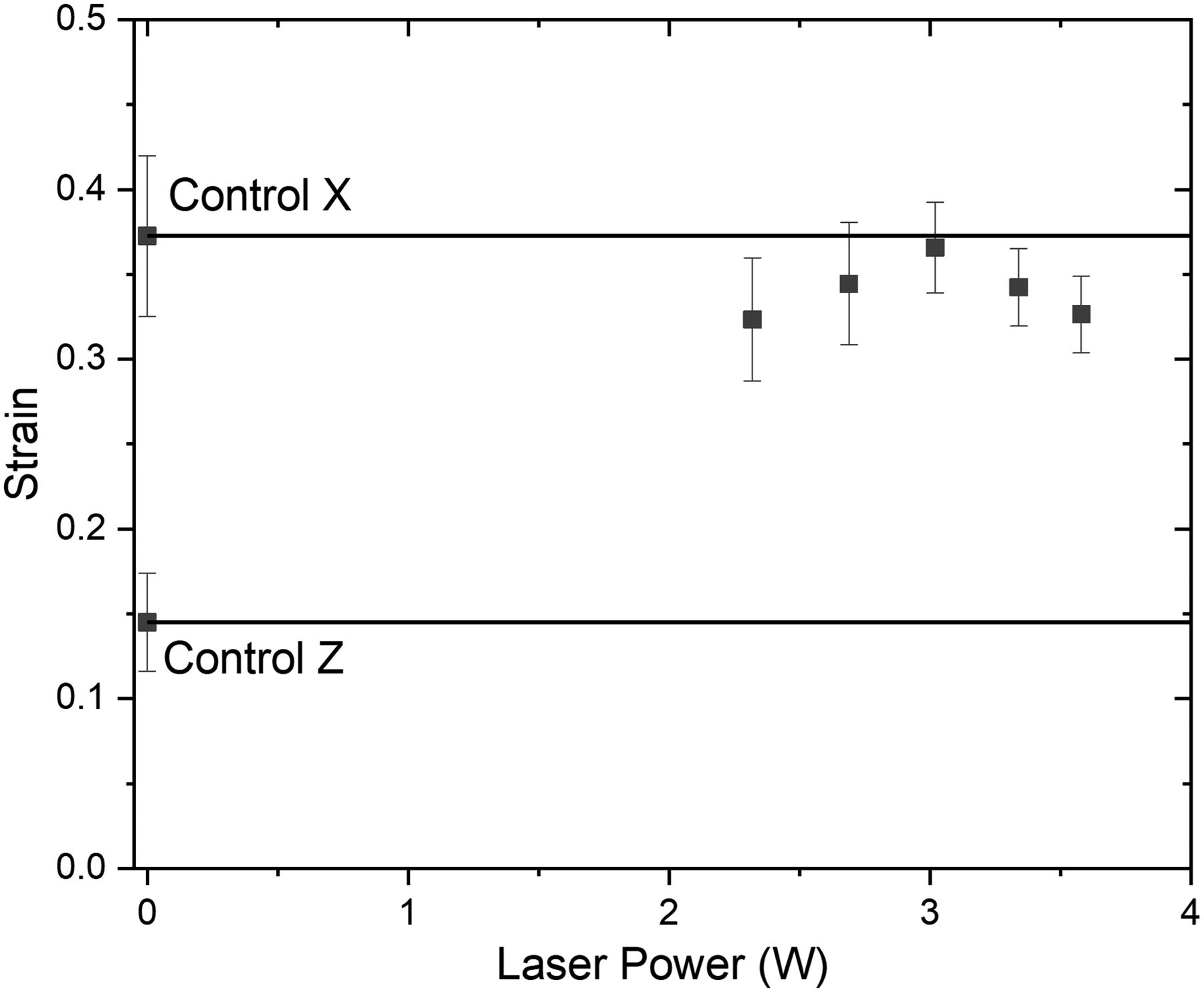
Strain data versus laser power.
The strain in the laser samples initially rises with laser power up to 3 W, followed by a continuous decrease. At 3 W, the strain measures 0.366, marking a 154% increase compared to the control sample. This indicates that the material at the fracture surface can elongate three times as much as the control sample before fracturing. At the molecular magnification, the fracture of polymer material contains stretching, elongating, and breaking of polymer chains, or separating polymer chains. The disparity in strain between the laser sample and the control sample suggests that at 3 W, the laser sample is able to elongate 2.5 times as much as the control sample before the polymer chains start to break. This implies a smaller radius of gyration for polymer chains in the laser-treated sample (that with a smaller radius of gyration, the polymer chains are in a less stretched state, thus allowing for more elongation before fracture), potentially due to the increase in relaxation during the cooling process.
Fracture behavior
The microscope images depicted in Figure 7 reveal distinct characteristics of the samples. In Figure 7A, the control Z sample exhibits a clean fracture surface with minimal evidence of plastic deformation, fracturing precisely at the interlayer interface. This underscores the weak mechanical strength depicted in Figure 4 and supports the assumption of minimal reptation occurring across the interlayer interface. Conversely, in Figure 7B, the 3 W laser sample shows a fracture surface breaking into layers, indicating that the weakest interlayer interface possesses comparable strength to the inner layer region along the build direction. This observation can also serve as indirect evidence for polymer reptation across the interlayer interface. The fracture surface is located close to the interlayer interface, instead of crossing layers. This means that even though the laser treatment improves the bonding at the interface, the material strength along build direction is still not uniform.
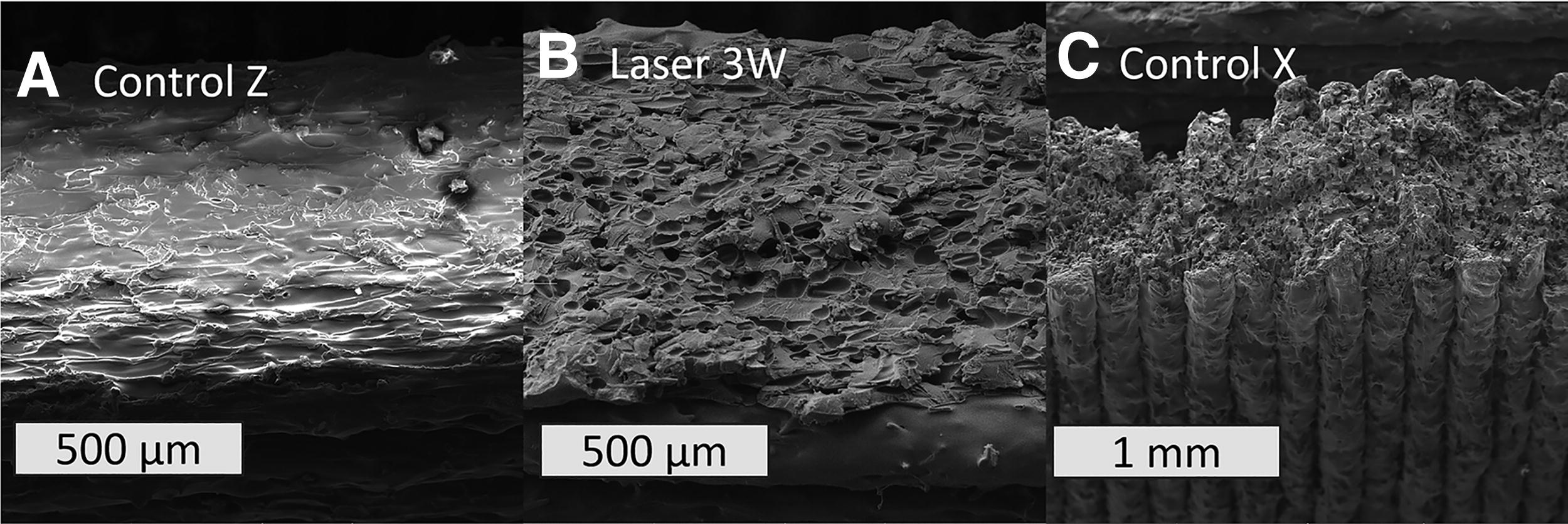
SEM images of fracture surface for
Moving on to Figure 7C, the fracture surface of the control X sample shows a rough surface. In this sample, the tensile test is performed along the in-plane direction, in which most of the CFs are aligned. Due to the weak strength between layers, the fracture surface also contains lots of vertical planes between layers instead of a continuous horizontal fracture surface. No necking behavior is witnessed in the Control X sample. This result fits the finding in strain data that no obvious strain value is observed for sample tested along X direction.
Conclusion
This study conducts a thorough examination of how innovative in-process laser heating affects the mechanical strength of CF-reinforced PEEK material. Initially, 3D-printed PEEK samples exhibit mechanical strengths of 9.3 MPa and 85.4 MPa along the build and in-plane directions (along the deposited track), respectively, due to the nature of the extrusion technique. With the implementation of laser heating, there’s a significant enhancement in the mechanical strength of 3D-printed PEEK—up to 60.5 MPa along the build direction. The strain value at fracture also increased to 250%. The authors link these differences to the effect of the laser heating process on molecular dynamics during deposition—specifically, reptation and relaxation influenced by the cooling rate. Consequently, the fracture mechanics shift from predominantly chain separation and extraction to increased chain elongation and rupture. This technique has the potential to extend polymer additive manufacturing to fields requiring high-temperature, high-strength composites, such as in-space manufacturing/assembly, small-batch production for aerospace parts, medical components, and prototypes.
Footnotes
Authors’ Contributions
Conceptualization, formal analysis, investigation, data curation, and writing—original draft preparation: P.H. Methodology: P.H. and S.T. Writing—review and editing: S.T., M.F.R., and K.H. Supervision and funding acquisition: K.H. All authors have read and agreed to the published version of the article.
Data Availability Statement
The data that support the findings of this study are available from the corresponding author upon reasonable request.
Author Disclosure Statement
The authors declare no conflict of interest.
Funding Information
Non funding was received for this article.