
Abstract
Polymeric tubing has played a crucial role in various industries. Manufacturing industries have traditionally used cutting methods for quality control, failure analysis, or to gain deeper insight into the device’s internal structure. A cross-sectional analysis of the tubes is required to control the manufacturing process of tubes produced by an extrusion process. However, small-scale factories and academic laboratories have so far used conventional hand cutters. Here, this study introduces a simple and novel analytical capability by fabricating and producing a dual-blade cutter tailored to the characteristics of the tubes. The dual-blade cutter, utilizing computer-aided design and three-dimensional (3D) printing, ensures low-cost parts, easy handling, and precise cutting. Through experiments, the cutting capability is verified by commercial polymer tubes. The dual-blade cutter is durable, allowing for an even distribution of cutting force. When cutting the outer diameter of the tube from 4 mm to 6 mm, the parallel angle deviation of the cut surface was 6–11%, demonstrating the ability to suppress surface roughness and burrs that may occur on the cut surface. It clamps the flexible tube effectively, minimizing tube deformation during cutting and increasing stability. As a result, the deformation of the tube can be quantified by ovality, and the values for hand-cut and cutter-cut are 11.5% and 4.3%, respectively. These suggested advantages could provide an inspiration for small factories and research institutes to reproduce our ideas or develop more efficient mechanisms. As additive manufacturing continues to advance, it is expected to significantly impact the prospective future of manufacturing processes, with expanded 3D printing capabilities via proposed practical application.

Introduction
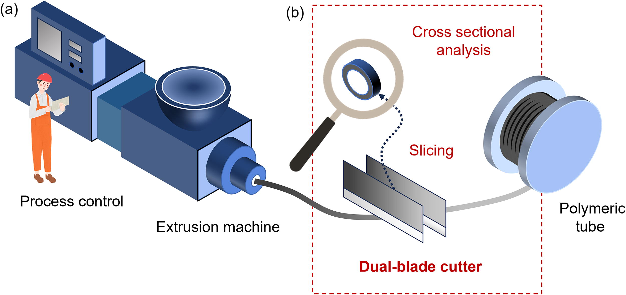
The motivation for this study was to address concerns raised by the authors during their research on polymer extrusion process optimization that resulted in measurement errors caused by plant operators using inappropriate cutting tools. Polymeric tubing has played a crucial role in various industries. 1 The tubes have uniform formability, high chemical resistance, and flexible and reliable mechanical properties. As such, tubes are used for protection, identification, sealing, and strain relief wherever wires and cables are used in electronics, 2 automobiles, 3 and airplanes. 4 As shown in Figure 1, in the tube production process, the material is consistently produced from the extrusion process machine and transforms into a tubular shape through quick drying. To achieve optimum tube diameter and surface quality, it is essential to precisely utilize the extrusion process by analyzing the internal and external quality of the tube being produced and then immediately optimizing the control parameters. 5 This is because various variables based on the supply of materials, the condition of equipment, and the environment of the factory affect the manufacturing process. In the general process control of polymeric tubes, the tube undergoes cutting to assess its internal structure, quality, or specific properties, which involves various analysis techniques such as cross-sectional analysis, microscopic examination, or cutting resistance testing.6–8 Recently, multilayer tubes that combine functional materials are being produced, so analysis through cutting is an unavoidable process. However, thus far, small-size factories and academic laboratories have primarily relied on cutting tubes using conventional simple hand cutters and imprecisely inspecting the surface. The unsophisticated manual cutting methods result in dowdyish tube inspection quality. The errors that curtail the parameter controllability of the tube production machine negatively affect quality control, productivity, and process operating costs. Thus, developing reliable custom equipment is an advantageous way to improve the accuracy of the cutting method, but research laboratories and small manufacturing companies in developing countries struggle to employ expensive custom equipment such as laser cutter.9,10 Therefore, developing a facile and cost-effective cutting polymeric tube method can provide a viable alternative to overcome these limitations and improve manufacturing productivity and analytical capabilities.
A facile slicing and cross-sectional analysis method applicable to precise measurement for process control of polymeric tube extrusion machines.
Thankfully, additive manufacturing has transformed numerous industries by facilitating the production of complex and customized components.11,12 Three-dimensional (3D) printing has emerged as a versatile method, which stems from the layer-by-layer construction of 3D structures directly from computer-aided design.13,14 Recently, 3D printing is extensively used across the globe for a variety of applications and the production of any form of open-source design in the field of prototyping of analytical engineering,15,16 manufacturing, consumer goods,17,18 including architecture, 19 automotive, 20 fashion, 21 and medical applications.22,23 Currently, innovations in materials are broadening the applications of 3D printing. Beyond rigid polymer materials, flexible parts using soft polymers and advanced robotics are being actively studied. 24 In addition, 3D printing utilizing multimaterials is also being studied, and ideas are being presented to further enhance mechanical and electrical functionality by using reinforcing materials such as carbon or fusing metal wires and conductive structures.25,26 The potential of 3D printing to revolutionize industries and impact market penetration is significant, presenting abundant opportunities for businesses aiming to enhance manufacturing efficiency and reduce costs.27,28 By taking advantage of additive manufacturing, facile cutting devices can be suggested.
Here, we propose designing and fabricating a cutter utilizing 3D printing intended for facile analysis by cutting tubes into smaller pieces. The proposed dual-blade cutter, characterized by two cutting edges rather than one, offers various advantages, including improved cutting efficiency, enhanced precision, and increased versatility across diverse applications. Leveraging 3D printing for dual-blade cutter fabrication has many benefits, enabling the creation of intricate geometries, customization for specific cutting tasks, and rapid prototyping of designs. Moreover, to fully harness the potential of 3D-printed dual-blade cutters, challenges such as material selection, and reliable tests will be addressed. The design and fabrication process of the dual-blade cutter prioritizes simplicity, cost-effectiveness, and performance enhancement. Evaluation of cutting efficacy was conducted through optical microscope examination. The assessment included calculating the delta angle to ascertain the parallelism between the resultant cutting lines, indicating uniformity along with the tube’s sides. A systematic exploration was undertaken to clarify the influence of environmental parameter variations on the analytical slicing of polymeric tubes, revealing a noteworthy correlation between cutting parameters and ovality.
The planned research aims to achieve cost reduction, improve surface quality, and adapt cutting tools to evolving industrial requirements. 29 The realization of a cutter that can cut and analyze tubes, which is easy to design and manufacture, and the low-cost method can provide high accessibility to many researchers and engineers. The proposed device’s simplicity, lightweight construction, and durability make it highly suitable for practical applications. Therefore, this study’s results will improve productivity, precision, and efficiency in manufacturing and analytical fields.
Materials and Methods
Materials
The product design facilitates Fusion360 3D design software. The fabrication functionalizes a 3D printer (Flashforge Adventure, FDM type). The printer nozzle diameter is 0.4 mm (default). The nozzle diameter can be increased or decreased to 0.6/0.3 mm (optional) to control productivity or resolution. The print speed is 10–150 mm/s, the layer thickness is 0.1–0.4 mm, and the print precision is ±0.1 mm (test of a 100 mm cube). The printing parameters are optimized through repeated tests. The filament specification is a diameter of 1.75 mm and a temperature of 190–220°C. The 3D printing filament (1.75 mm PLA Pro Filament 1.0 Kg Red). The critical cutting part, blades (DORCO Model NO. DN50), cost less than 1 USD, which supports ultra-low-cost device manufacturing. For assembly, use M3 Screws (M3 × 20 mm), M3 Screws (M3 × 14 mm), M3 Nuts (M3 × 3 mm), and M3 Washers (M3 × 3 mm). For cutter verification, use polyurethane tubes with various outer diameters and inner diameters (4–2 mm, 8–5.5 mm, 8–5 mm).
Analysis
The cut surface quality is analyzed using a microscope (Olympus SZ61). The magnification range of SZ61 is extended from 6.7× to 45×, providing smooth macro–micro zoom for a wide zoom ratio of 6.7:1. A drying oven is used for environmental reliability analysis. The temperature control range is room temperature (RT) (+)20–300°C. A refrigerator (Changlong ORD-320BWH) is used for low-temperature testing. The precision measurement of the dimension is performed using a caliper (Mitutoyo 500-156-30 200 mm).
Design and fabrication
The utilization of 3D modeling software proves instrumental in constructing a comprehensive feature-based 3D parametric solid modeling.8,17 The process facilitates the precise depiction of impressions in three dimensions, ensuring enhanced control through the utilization of high-precision measuring instruments. Following the creation of each 3D model, the models are converted into stereolithography (STL) files, which meticulously specify the object’s surface geometry. 17 These STL files are subsequently exported to a 3D printer, where the splicing process commences to prepare the part for printing. Splicing involves the layer-by-layer creation of the print design, incorporating the design of fill patterns for the internal volume of the part. As predicted, the utilization of commercially packaged filaments ensures the continuous and stable extrusion of the printing process. Notably, the design of the objects prioritizes compatibility with 3D printable materials, such as polylactic acid (PLA), acrylonitrile butadiene styrene (ABS), and thermoplastic polyurethane (TPU).30,31
Results and Discussion
Printing
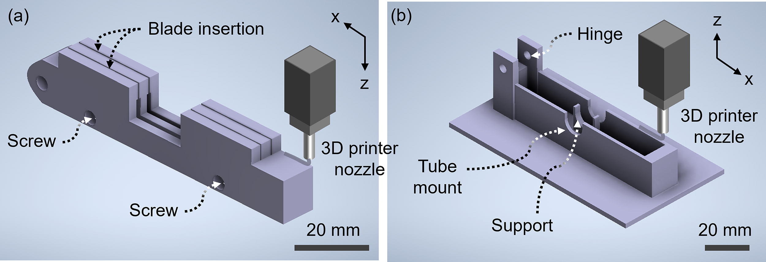
Figure 2 shows the core parts of the proposed dual-blade cutter, the base, and the top holder, which are 3D printed. The parts undergo printing on the bed of the 3D printer, while the printer nozzle extrudes filament from the bottom. Figure 2a is the holder that holds the blade. It operates at the top when the cutter is assembled and has a hole where the blade can be inserted into the gap and secured with a screw. The design incorporates a mechanism for easy blade replacement, allowing users to switch between different blade types or conveniently replace worn blades. Designed with ergonomic considerations, the dual-blade cutter features a design where the cutter base and blade holder accommodate the user’s grip. The blade holder can be customized to fit a variety of hand sizes. Figure 2b is the base that supports the holder’s motion and mounts the tube. It accommodates two blades arranged side by side, optimized for precisely cutting semirigid polymeric tubes. A hemispherical hole is in the center for mounting and removing the tube. In the middle of the tube, a support structure prevents the tube from bending and the cutter force from being dispersed. This structure is explained in the “Structural verification” section. The wide bottom plate of the base allows the cutting force to be transmitted to the tube during operation. Without the vast structure, the cutter may fall over, causing injury to the user or errors in tube cutting. There are holes for assembly with the top holder. A hinge that allows 1 degree of freedom rotation can be made using a screw.
3D printed parts for the cutter.
Assembly
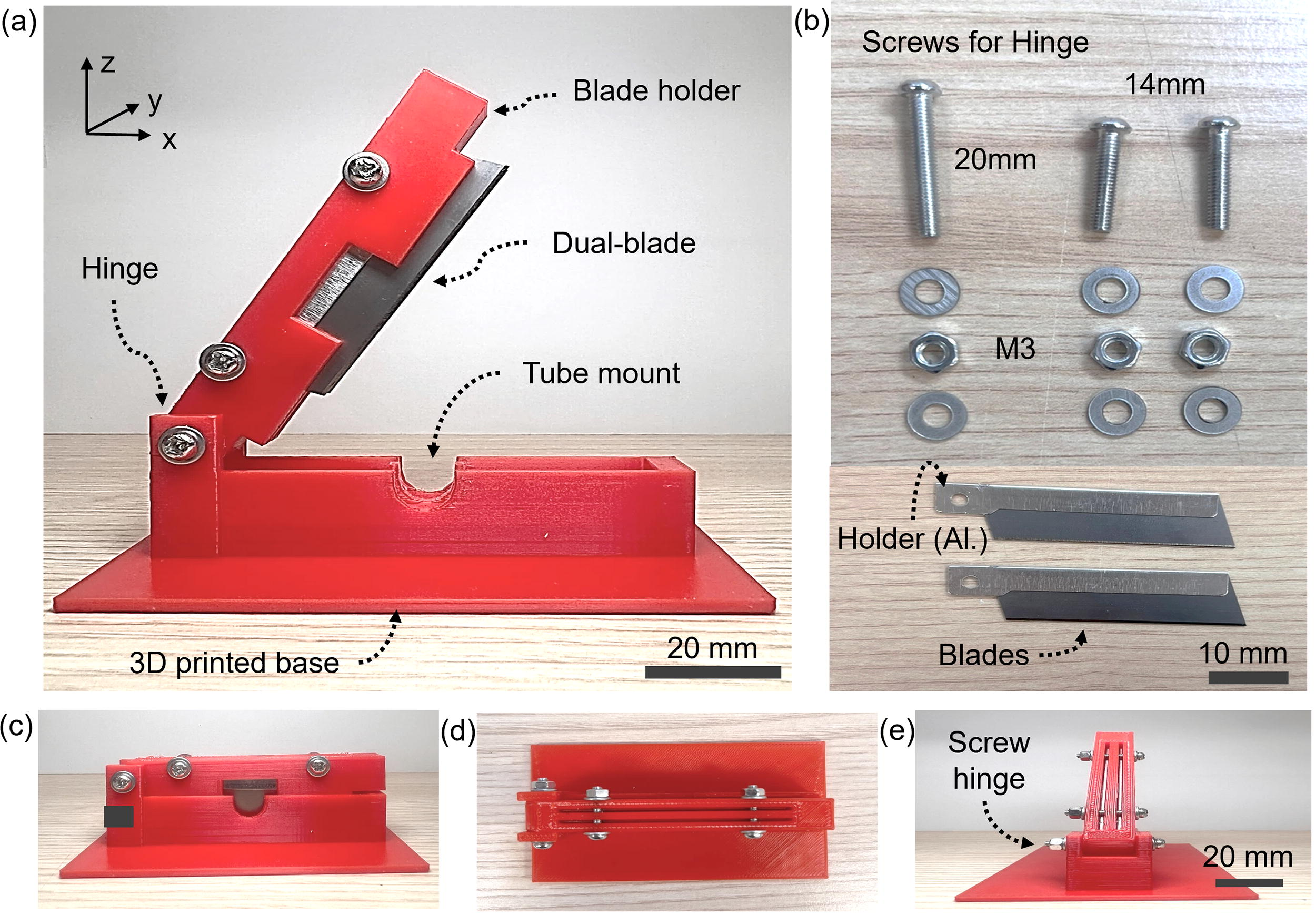
The prototype of the cutter is shown in Figure 3a. The assembly details of all 3D printed components are shown in Figures 3b–e to guide the user. The assembly is simplified into two simple steps using fixing tools such as screws, as shown in Figure 3b. First, the blade is inserted into the holder. The blade is finally fixed using M3 short screws (14 mm), washers, and nuts, as shown in Figure 3c. The worn blade can be moved ± along with the x-axis and fixed due to repeated cutting, which can extend the cutter’s life. In the following steps, the holder is connected to the cutter base using M3 long screws (20 mm), M3 washers, and M3 nuts, as shown in Figure 3d. The long screws connect the holder and the base while also serving as the axis of the hinge, as shown in Figure 3e. This simple assembly process ensures efficient, safe, and low-cost fabrication.
Parts assembly guidance.
Slicing capability
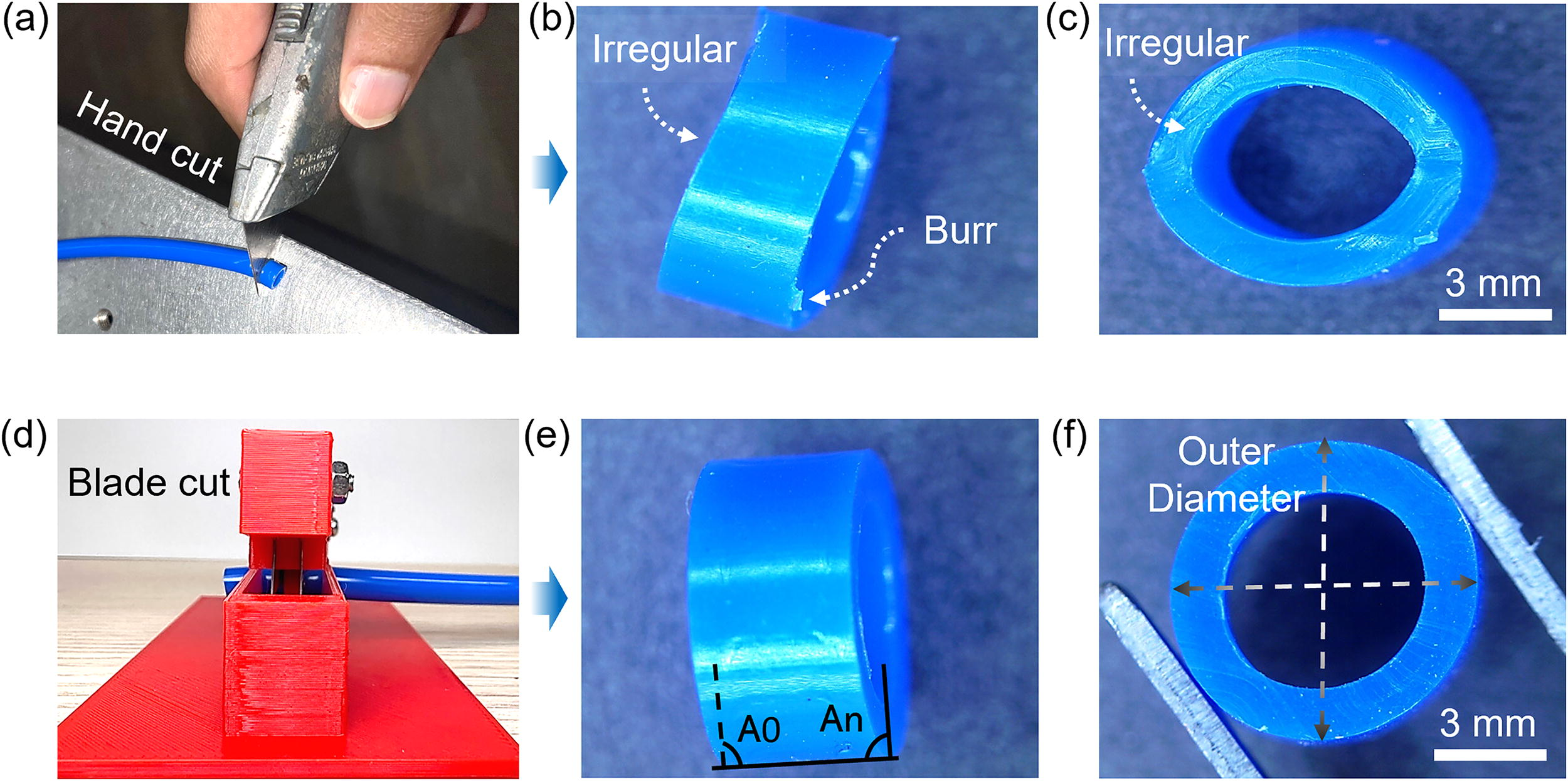
The performance evaluation of the dual-blade cutter includes a comparative analysis with the single-blade cutter knife for semisolid polymer tubes. Figure 4 shows the effect of compressive force on the tube cutting and allows for a contrasting analysis of the dynamics between the single-blade and dual-blade cutters. The effect of compressive force during the cutting process varies between the two types of cutters. As shown in Figure 4a, the single-blade cutter knife produces errors when the pressure is concentrated on a single blade. As shown in Figure 4b, the cut surface has waves. This is because the flexible tube moves while the cutter cuts along with the tube cross-section, or tensile contraction occurs in the direction in which the cutter moves. This is mostly caused by the nonfixation of the cutter. In addition, there are particles such as burs on the cut edge. This is because the cutter blade does not perfectly traverse the tube cross-section. As a result, this can lead to inconsistent cutting and jagged edges or require multiple passes to achieve the desired cutting quality. The irregular errors in the cross-section are also shown in Figure 4c. The uneven roughness of the surface is analyzed through the photographs, and the cross-sectional shape of the circular tube is deformed into an ellipse due to the concentrated pressing force of the cutter. The single-blade cutter knife concentrates the entire force on a narrow area of the tube when in contact, which increases the force applied to the tube surface. In addition, the cutting direction deviation is caused by the knife, which is not fixed and thus the cutting direction changes continuously, causing deformation or collapse of the tube. The deformation is mainly noticeable when the tube is thin. In contrast, the dual-blade cutter shown in Figure 4d can evenly distribute the compressive force to the two blades when in contact with the tube. The two blades, which are well fixed, provide a force perpendicular to the surface of the tube, which enables efficient cutting. This force distribution effectively relieves the excessive stress applied to individual blades. It reduces the possibility of tube deformation, damage to the cut surface, or dimensional changes, as shown in Figure 4e and f. The deformation of the tube can be quantified by ovality, and the values for hand-cut and cutter-cut are 11.5% and 4.3%, respectively. Ovality will be explained in the “Mechanical reliability” section. As a result, the dual-blade design applies to a more balanced force, which increases the cutting precision and reduces the risk of negative impact on the tube. In addition, the cutter base is specifically designed to accommodate the compressive force, and the dual-blade configuration supported by the cutter base improves stability during the cutting operation. This design feature ensures a controlled path, facilitating accurate and clean cutting. Dual-blade cutters offer distinct advantages over single-blade cutters in tube cutting applications, improving cutting precision and efficiency.
Cutting dynamics.
Structural verification
Figure 5 provides a guide for predicting deformation and reliability for selecting 3D printing materials. As described in Section 3.1, the printed base has supports between the tube mounts formed on both walls. Since it is a structure specifically designed to distribute the transmitted force, the phase of the force distribution can be verified. First, the tube deformation can be eliminated to fix the tube during the tube process stably. Second, since the cutting force is evenly and stably transmitted to the nondeforming tube, a parallel, and improved surface roughness cutting surface can be created. This structural design is verified for functionality by simulation. As shown in Figure 6a, forces of 1, 50, 100, 150, and 200 Pa are provided in the moving direction of the (−)z-axis of the cutter. As a result, the von Mises stress mainly occurs in the support formed in the center. This is because the force provided by the two parallel-aligned blades is transferred between the tube mounts, which exerts a large force in the (−)z-axis on its support. Without the support, the tube bends in the (−)z-direction, which means the cutting quality is poor. As shown in Figure 6b, mechanical deformation of the support occurs when an increasingly higher force is applied. The deformation of the support occurs in the form of widening along with the y-axis. The proposed support structure is advantageous in preventing the deformation of the tube as it has a wider dimension. In addition, if it is made into a variable-turn assembly/disassembly type, it will be possible to precisely cut tubes with various diameters. Of course, the deformation can be reduced by increasing the dimension of the support, but the dimension was fixed, and the suitability of the material was examined. Figure 5c predicts the support deformation according to the 3D printing filament material. As a result, this study uses PLA material for printing. When the force applied to the cutter is 50 Pa, the maximum displacements of the PLA, ABS, and TPU supports are 6.45E-7 mm, 9.86E-7 mm, and 1.38E-5 mm, respectively. When it is 200 Pa, the displacements are 2.58E-6 and 3.79E-6 mm. The deformation increases linearly with the applied force in all PLA, ABS, and TPU filaments. The deformation of PLA is the smallest, followed by ABS and TPU. PLA has the smallest deformation, making it suitable for cutters that must avoid physical deformation. It also has the advantage of being made of lactic acid, which does not release toxicity during the printing process and is harmless to the human body. ABS has good impact resistance and similar mechanical properties to PLA but has the disadvantage of being harmful to the human body. TPU has relatively flexible mechanical properties. Since the occurrence of displacement increases the cutting tolerance, material selection, and design for minimum displacement are necessary. By using custom filaments, we can expect to improve the strength or expand the application range. For example, there has been research into producing samples with a tensile strength that is more than 200% higher than that of existing materials such as ABS by using new printing materials such as polyetheretherketone. 32 Figure 5d shows the maximum von Mises stress of the cutter support printed with PLA material. When the force applied to the cutter is 50, 100, 150, and 200 Pa, the maximum stress is approximately 200, 400, 600, and 800 Pa, respectively. The stress occurrence area appears symmetrically on the support as the displacement occurs and does not appear uniformly on the contact surface with the tube. This means that it is more efficient to improve the strength by adjusting the size rather than the support structure. 31

Predictable deformation and reliability.

Changes in angular deviation according to cutting repetitions up to 100 times.
Mechanical reliability
As shown in the solid line in Figure 5a, each sample is measured in turn. The results show that the tube’s diameter and thickness are factors affecting the repeatability of the cutter. The maximum and minimum deviations of the OD 8 mm (thickness 1.5 mm) cut are about ±11%. As shown in Figure 5b, the maximum and minimum deviations of the OD 8 mm (thickness 1.25 mm) cut are about ±10%. Figure 5c shows that the OD 4 mm (thickness 1 mm) has a deviation of about ±6%. It means that a smaller diameter of the tube increases the life of the cutter rather than the thickness. The difference between the 1.5 and 1.25 mm thicknesses is about 1%. However, comparing OD 6 and 4 mm with 1.25 and 1 mm thickness tubes shows remarkable results with about a 6% difference. In addition, the dotted line in each plot is the trend line of the measurement data. Figure 5a shows an increasing trend, and Figure 5b shows a decreasing trend. This is due to the initial angular deviation of the blade when the cutter is mechanically assembled. The dimensional tolerance of the 3D printed parts and the blade assembly using screws can cause a slight tilt of the blade. The occurrence of the trend means that the assembly deviation of the blade grows further due to repeated contact and friction with the tube. The initial tilt of the blade can accelerate the angular deviation. If the precision printing and assembly that consider the tolerance of the micrometer level are accompanied, the phenomenon of the angular deviation increasing or decreasing can be reduced. As shown in the cross-section of the cutting mode on the left side of Figure 5, the trend change of the cutter is significant, especially in the tube with a large diameter, because the cutter provides greater force and deformation during the cutting travel in the −z-direction. The smaller the tube, the more stable the cutting quality can be maintained, and the failure extension can be prevented.
To verify the repeatability of the blade and the reliability of the factory’s available environment settings, it is essential to understand the effect of tube ovality and temperature. This is because, in actual manufacturing environments, thermal fluctuations can induce elastic changes in the polymeric materials, leading to dimensional changes. In Figure 7 and Table 1, we measured the tube’s transverse OD (OD max.) and vertical OD (OD min.) after approximately 100 attempts to cut the tube through observation. When cutting the tube, a force is transmitted to the surface of the tube, and the molecular chain bonds of the flexible polymer undergo a process of deformation and then breaking. 10 Simultaneously, the blade condition of the cutter affects the concentrated force to break the polymer bonds. As the number of cuts increases, the blade edge begins to wear out, and the concentrated force gradually decreases. The measurement results show that the ovality increases noticeably as the number of cuts increases. As the cutter wears, the deformation of the tube increases, and the ovality rises to 4.33%, 6.83%, and 9.66% at 0, 50, and 100 times, respectively. In Table 1, the tube and cutter are tested at various temperatures (RT, 45°C and 10°C). The high-temperature setting was because the tube had a temperature of approximately 45°C when measured immediately after being ejected from the injection machine. The ovality measurements after cutting are carefully recorded and analyzed. The experimental results showed a significant correlation between temperature and ovality. In particular, as the temperature increased to 45°C, the ovality of the tube increased to 11.83% due to the change in thermoelectricity. In contrast, when the temperature decreased to 10°C, the ovality decreased to 5.66% due to a more rigid polymer bonding state. The tube’s resistance force, which acts in the opposite direction to the force provided by the blade, succeeds in cutting the tube. The flexibility independent of temperature and dimension increases at high temperatures, and a relatively flexible tube has a lower ability to resist the cutting force of the blades. As a result, the excess cutting force is developed into deformation of the tube. In addition, as the temperature of the cutter increases and comes into contact with the tube, it may play a role in making the tube flexible through heat transfer in a microscopic area. Even after 100 cuts, the ovality at 10°C shows an improved quality of 5.66%. The thermoelastic recovery of the polymer is rather beneficial to the cutter’s life. This result implies that it is advantageous to cut the tube at a low temperature to minimize dimensional changes. To verify this effect, the Δ angle was measured at these various temperatures. It was confirmed that the shear strength showed more excellent recovery at low temperatures than at high temperatures. The results of the study reveal the subtle relationship between temperature change and tube ovality, which helps to unveil the cutting ability of the cutter under various thermal conditions and to understand the behavior of the tube deeply.
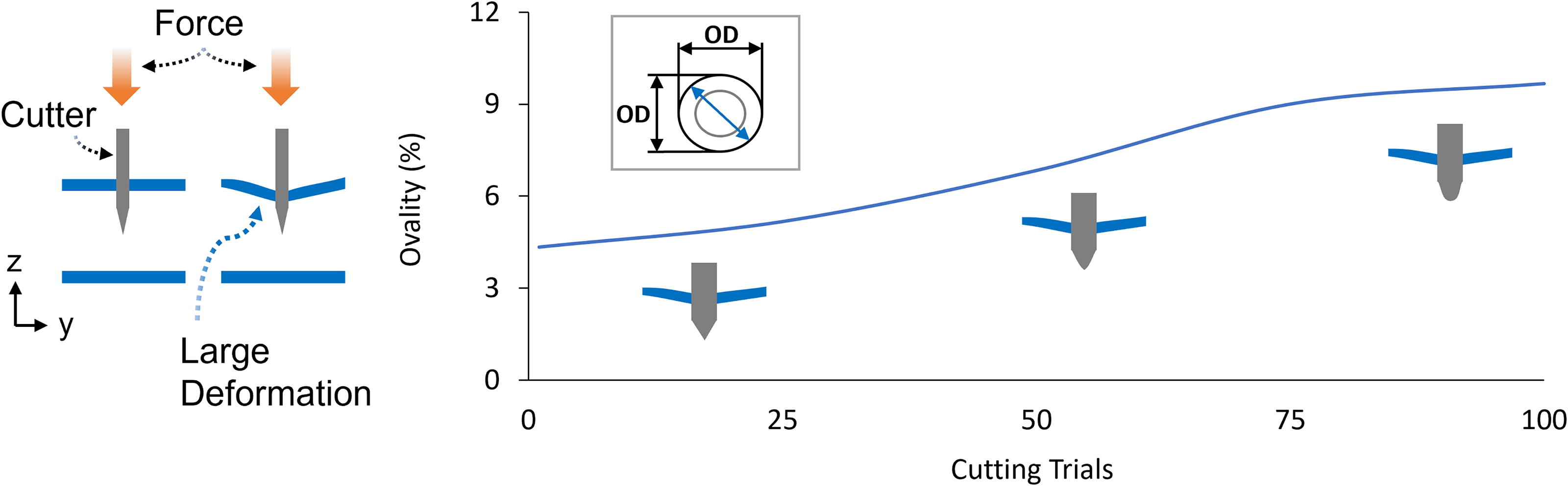
Tube ovality according to 100-cycle cutting for providing reliability of the cutter.
Measurement of the Ovality of the Tube with Temperature Variation
RT, room temperature.
As people have experienced deformation depending on the cutting speed when slicing vegetables during cooking, we additionally examine the ovality of the tube according to the cutting speed. The fabricated cutter rotates 45° counterclockwise (1/4 π radian). The cutter motion is vision-monitored toward the (−)y-axis. The cutter blades are set to touch the surface of the tube after 3 and 12 ms, maintain speed, and then cut the tubes. The rotational angular velocity (ω = dθ/dt) is calculated using the measured time. The measured angular velocities are 8.33 and 2.08 rad/s. At this time, the tangential velocity (VT = r · ω) can be calculated using the rotational radius of 40 mm, where the cutter meets the tube, which is half of the blade holder length of 80 mm. Through these steps, the VT set for the experiment is 333.2 and 83.2 mm/s, respectively. As a result, the quality of the tubes sliced at fast and slow speeds can be compared, as shown in Table 2. As a result, the ovality quality at 333.2 mm/s is 4.33% and at 83.2 mm/s is 7.02%, respectively. At high temperature, the ovality is even larger, 6.11% and 13.36%. As discussed above, the resistance of the tube acting in the opposite direction to the force provided by the blade is beneficial to the tube cutting. In our experiment, the cutting force is dominated by the load and impact according to F = m · a. When the weight of the blade cutter is fixed, the cutting impact is determined by the tangential velocity of the blade cutting. A fast tangential velocity means that a large impact is provided to the surface of the tube. The deformation of the tube due to the impact is mainly due to the molecular bending mechanism. From the molecular point of view, deformation due to the impact creates a combination of molecular chain bending and torsion. According to the study of Xie et al., through the comparison of molecules, it was suggested that molecules with low-molecular chain value or flat molecules have smaller deformation under the impact load and better impact resistance. 33 Not only the results shown in Table 2 but also in vegetable cutting in our daily lives, cutting using a large impact means that deformation of the object can be reduced.
Measurement of the Ovality of the Tube with Cutting Speed Variation
Conclusions
The study investigates the design and fabrication of a dual-blade cutter using 3D printing. We designed a cutter tool based on simple blades. The dual-blade cutter fabricated by 3D printing offers enhanced user adaptability based on the advantages of low-cost components. The simple assembly process provides efficiency and precision. Considering the flexible nature of the tubes and the structural design using simulation, it is shown to be excellent in distributing the force required for cutting evenly, thereby reducing the risk of tube deformation. We demonstrated its capability through commercial tube cutting, analysis, and demonstrated its reliability through repeated experiments. We discussed it in more depth by varying the temperature and operating speed.
Although this is a specific field study on a simple slicing method for cutting and analyzing tubes, the results would be more convincing if the tube types and design structures were varied. Further research can focus on diversifying and optimizing the design and materials to meet the needs of a broader range of industrial applications.
The proposed idea of cutting and analyzing tubes successfully achieved the goals of cost reduction, improved surface quality, and adaptation of cutting tools to respond to industrial requirements. The experimental approach we performed provides a better understanding of tube slicing dynamics, promising improved precision and efficiency in industrial applications. It can also improve the precision of the analysis process in low-income countries and small laboratories, thereby enhancing manufacturing and research capabilities. Moreover, by further expanding the scope of the use of 3D printing as a tool in the field of analysis, it will contribute to enhancing the scalability of 3D printing and additive manufacturing technology.
Footnotes
Authors’ Contributions
H.W.C.: Review and editing (lead), methodology (lead), and visualization (lead). T.A.: Validation (lead) and writing—original draft (lead). J.K.: Conceptualization (lead), writing—original draft (supporting), resources (lead), and supervision (lead).
Author Disclosure Statement
No competing financial interests exist.
Funding Information
This research was supported by the Bisa Research Grant of Keimyung University No. 20230193.