
Abstract
Access to clean water remains unattainable due to water pollution caused by various sources. Conventional water purification methods fall short of eliminating micro-sized and soluble contaminants, promoting the exploration of innovative approaches utilizing nanomaterials. Thus, metal-organic frameworks (MOFs) have attained considerable attention for water filtration, exhibiting high pollutant adsorption potential due to their abundant and well-organized nanoporous structure. However, a major limitation of MOFs is secondary contamination arising from MOFs leaching and detaching from the substrate on which they are synthesized. Herein, we propose a novel design and manufacturing of MOF-laden monolith 3D structure (MLMS) to minimize such drawbacks. Using extrusion-based additive manufacturing, we constructed the MLMS with macroscale porosity, employing a Moiré pattern to enhance its mechanical strength in different dynamic fluid conditions. Copper-based MOFs (Cu-MOFs) were integrated within the MLMS with high adhesion by the introduction of heat treatment, thereby minimizing leaching and detaching while maintaining the pollutant absorption capability. Furthermore, the Cu-MOFs’ growth, distribution, and adsorption efficiencies have been studied by growing them on various commercially available 3D printing polymers [polylactic acid, polyethylene terephthalate glycol (PETG), acrylonitrile butadiene styrene, and thermoplastic polyurethane]. The results show that the surface area covered by the MOFs ranges from 12.8% to 75.8% depending on the number synthesis cycle. In addition, a reduced leaching rate of 16.1% from the MLMS was observed at a high-water flux (4.14 × 10³ L m−2 h−1), demonstrating significant adhesion between the MLMS and Cu-MOF nanoparticles. The adsorption efficiency of malachite green dye was further analyzed with Cu-MOFs@MLMS, showing removal efficiency of 94.77% and 36.42% under stagnant and dynamic flow (1.18 × 10³ L m−2 h−1) conditions, respectively, when MLMS was made of PETG. The findings reveal the MLMS’ potential in removing contaminants under both stationary and flowing systems and the broad applicability of MOFs-loaded 3D-printed monoliths for scalable and efficient water filtration systems.
Introduction
Fresh water, the indispensable element for the existence of life, has become so scarce that 2 billion people all over the world are reported to suffer from lack of access to it according to the United Nations World Water Development Report 2023. 1 Other than climate change, pollution growth, urbanization, and industrialization, pollutants such as dyes, heavy metals, and persistent organic pollutants play a significant role in causing the scarcity of clean water. These pollutants are mostly derived from industrial processes, agricultural pesticides, and improper waste management systems. Industrial water pollution, largely contributed by various dyes, alone was reported to be responsible for 20% of global water contamination. 2 Consequently, organic dye in drinking water was reported to cause allergic and toxic reactions in humans and other animals. 3 Among different types of dyes, malachite green (MG) was reported to be fatal having the potential even to cause cancer, liver diseases, and neurological issues. 4 Its existence in the water even at low concentrations was found affecting the aquatic lives by initiating detrimental effects in gill, intestine, kidney, and gonads of the fishes and animals living under water. 5 Therefore, to protect the aquatic fauna and ensure a healthy under water environment, removal of MG at a tolerable level is a must.
Traditional methods such as coagulation, sedimentation, and physical filtration often require higher operating energy and involvement of chemicals, resulting in secondary contaminations. A widely used disinfecting process, chlorination produces trihalomethanes which may initiate the process of causing cancer.
6
As a result, innovative approach is a necessity in dealing with soluble micro-nano size contaminants like MG. Metal-organic frameworks (MOFs), one of the most researched nanomaterials, can offer unique advantages in water purification due to their high surface area,
7
tunable pore size,
8
and selective adsorption properties.
9
MOFs are versatile and can be designed to target specific pollutants, including heavy metals, dyes, and organic micropollutants.10,11 MOFs such as copper-based MOFs (Cu-MOFs), MOF-199, ZIF-8, ZIF-67, MIL-101, MIL-53, and UiO-66 have shown promising outcomes in adsorbing various pollutants from water.12,13 For example, utilization of Fe3O4@AMCA-MIL-53(Al) nanocomposite was reported for the adsorption of 0.9 mmol/g MG.
14
Cu-MOF nanosheets were used to adsorb methylene blue, methyl orange, rhodamine B, and Congo red, where the maximum adsorption took place due to cation (from dye)–
Although MOFs exhibit high adsorption capacities, it is difficult to retrieve the MOFs or MOFs-composite crystals from the water. Thus, the secondary contamination by the MOFs is a concern and needs to be addressed for its sustainable and benign application. 18 Such contamination may also occur due to the detachment of the MOFs from the host substrate on which those are synthesized. The detachment of the MOFs from the substrate may be attributed to the weak adhesion between the surface and the MOFs, the MOFs’ synthesis processes, and conditions of the applications such as using the MOFs-composite filters in flowing water or stagnant water, operating temperature, humidity, and the type of substrates used. 19
Embedding MOFs in 3D-printed monolith porous hosts followed by heat treatment has been proposed to mitigate MOF stability issues. The porous hosts offer additional surface area and facilitate the controlled exposure of MOFs to the liquid solution. Porous hosts like carbon, silica, and polymer matrices provide structural stability, reducing the likelihood of secondary contamination.12,20,21 This method attaches MOFs inside a stable framework, therefore preventing secondary contamination and simplifying the handling and retrieval of the material. Mixed-matrix membranes containing embedded MOFs, for instance, were produced which exhibited effective pollution adsorption and simple retrieval after filtering. 22 These membranes, however, permit extremely low flow flux (less than 40 L m−2 h−1), which makes usage under flow circumstances challenging. Combining MOFs with porous hosts enhances mechanical stability and adsorption efficiency while addressing secondary contamination risks. MOF-199-laden carbonized wood structure was studied, which demonstrates 89.2% adsorbance of methyl orange dye from steady-stagnant water. 12 Similarly, Cu-MOFs grown on 3D-printed polylactic acid (PLA) 23 and acrylonitrile butadiene styrene (ABS) 24 host structure as films were used to adsorb organic dye from steady-stagnant water. However, adsorbance of MG under higher flow flux will have volumetric benefit, but such studies are scarce in literatures.
To address these challenges, we propose to design and manufacture MOF-laden monolith 3D structure (MLMS) using extrusion-based additive manufacturing suitable for contamination eradication from high flow flux condition and minimal secondary contamination. 3D monolith structure is printed with polyethylene terephthalate glycol (PETG), PLA, ABS, and thermoplastic polyurethane (TPU) as the host following the Moiré pattern using additive manufacturing technology with different printing materials. Cu-MOF is then grown on the host structure at various rates for removal of the organic dye, MG from both stagnant and flowing water. To enhance the stronger adhesion between MOF and host interface, a heat treatment cycle is performed on the MLMS while maintaining structural integrity of the structure. Both the MG dye removal rates and MOF peeling rate are studied and reported in the paper. Our findings open the door for further studies into MOF-based filtration systems that can target a wider range of water pollutant.
Experimental Methods
Chemicals and materials
1,3,5-benzene tricarboxylic acid (H3BTC), copper nitrate trihydrate (Cu(NO3)2·3H2O), triethylamine (TEA), and ethanol were purchased from Sigma Aldrich and used without further purification. For 3D printing, commercially available filaments were purchased, and the materials used were PLA, ABS, TPU, and PETG. These materials contain functional groups, such as –OH and –COOH, which promote the formation of nucleation sites critical for MOF growth. These functional groups can also engage in hydrogen bonding, electrostatic interactions, or π–π stacking with the MOF linkers, further enhancing adhesion. In addition, they were selected based on their availability, accessibility, and ease of printability with standard extrusion-based 3D printers, making them well-suited for community-based manufacturing. While other materials, such as PEEK (polyether ether ketone), are available, they often require specialized equipment and advanced expertise to print and were therefore excluded from this study.
Design and 3D printing of the host structure
The MLMS was 3D-printed following different Moiré patterns.25-27 To design various Moiré patterns, the change in parameters such as raster angle (α) and air gap or line spacing (
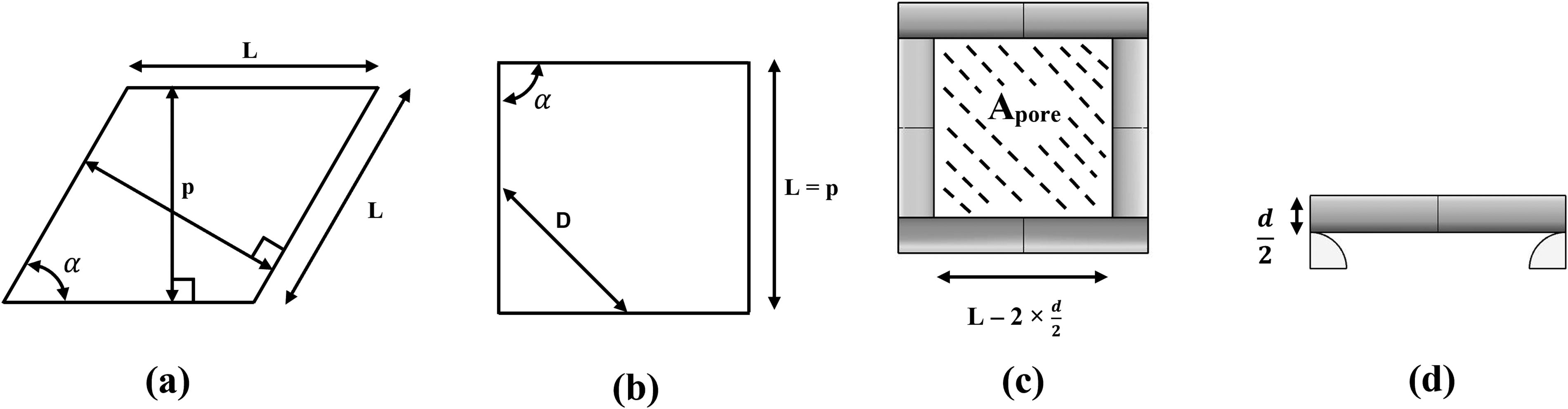
Designing porous host of “p” air gap and α raster angle using Moiré pattern. Schematic of
The pattern density depends on the raster angle (
The Moiré pattern was systematically employed in 3D-printed hosts’ design which is printed with customized G-code for achieving high precision in 3D printing at the intended spacing and angle using Ender 3 extrusion-based printer. Considering different Moiré parameters, a 3-mm cylindrical host structure with a diameter of 25.4 mm was printed with 15 layers consecutively as shown in Table 1. The printing temperature was kept at 210°C, 220°C, 240°C, and 240°C for PLA, TPU, ABS, and PETG, respectively. The printing speed was 50 mm/s, and Ender-3 was used for the 3D printing. The diameter of the printed raster was 0.2 mm for all the MLMSs. Cu-MOFs were grown on the host structure using the protocol discussed in the subsection “Cu-MOFs synthesis process on the host.” The MOF growth density was controlled with the number of synthesis cycle which was then measured as surface coverage using ImageJ software. These MOF-laden monolith 3D structures are defined as MLMS, which contains macroscale porosity designed by Moiré pattern and nanoscale porosity introduced by the MOF structures. It can be observed from Table 1 that the porosities of the MLMSs increase with the increase in the air gap due to the decrease in the raster density. However, the change in the raster angle does not impact the porosity, as it changes the orientation of the patterns.
Designing MLMSs Using Different Moiré Patterns
MLMS, MOF-laden monolith 3D structure.
Cu-MOFs synthesis process on the host
Cu-MOFs were synthesized following a similar procedure reported in the literature.23,24 An 80 mL solution containing ethanol and deionized (DI) water at a 1:1 volume ratio was prepared. The 3D-printed host was treated in this solution for 3 h. After this treatment, the host structure was placed into an 80 mL solution having 1.32 g of H3BTC and 0.25 mL of TEA in ethanol–water (1:1 volume ratio) solution for 5 h. Finally, the host was treated with a solution made by dissolving 2.22 g of (Cu(NO3)2·3H2O) in 80 mL of ethanol–water (1:1 volume ratio) solution for 5 h. Then, the MLMSs were alternatively washed with ethanol and DI water to finish the growth of the first layer of MOF to manufacture the MLMS as shown in Table 1. The same procedure was repeated one more or multiple times to get two or multiple layers of MOFs’ synthesis on the MLMSs, respectively.
Heat treatment of the Cu-MOFs containing MLMS
After fabricating MLMSs, heat treatment was performed on them to improve the adhesion between the host and MOFs. The MLMSs were heat-treated in the VIVTEK muffle box furnace for 3 h at 60°C, 100°C, and 90°C for PLA, ABS, and PETG printing materials, respectively, which are near to their glass transition temperatures. The TPU was not heat-treated as its glass transition temperature is below the ambient temperature.
Adhesion test of Cu-MOFs on the MLMS
The adhesion force acting between the host substrate and MOFs was indirectly analyzed by introducing a high flow flux of water through the MLMS. The water was pumped at the two flow rates of 4.14 × 10³ L m−2 h−1 and 1.18 × 10³ L m−2 h−1 for 5.5 min. To investigate the adhesion in a no-flow condition, dye-containing DI water was used instead of only DI water. The MLMSs were submerged under the dye water for 2 h. The MLMS used for these tests included both the heat-treated and nonheat-treated samples. The areas covered by Cu-MOFs before and after tests were measured using ImageJ software to study the impact of heat treatment on the adhesion strength between the MLMS and MOFs.
Adsorption of MG by the MLMS
A solution of 1 mg/L MG was prepared for performing the adsorption test. The MLMSs were placed in separate beakers with 30 mL of the prepared solution in them for testing the dye removal performance from stagnant water. After 20 min, the MLMSs were brought out from the solutions. Using a UV–visible spectrophotometer, the change in the presence of dye was measured. A wavelength of 618 nm was used to analyze the MG removal as it exhibits its chromatic feature at that wavelength. 28 To study the removal performance by the Cu-MOFs hosted on the MLMSs, 30 mL of the prepared dye solution was pumped at 1.18 × 10³ L m−2 h−1 flow rate through the MLMSs. The filtered solution was analyzed by the UV–visible spectrophotometer to measure the removal performance of the Cu-MOF-based MLMSs.
The processes of removing MG dye from water have been schematically represented in Figure 2. Cu-MOFs were synthesized on the selected MLMS. When exposed to water containing the dye, these MOFs carrying MLMSs have the ability to adsorb the dye. In Figure 2(a), an MLMS was set in a tube through which dye water was pumped at a certain flow rate. The MOFs attached to the MLMSs adsorb the dye into their pores and let the water pass through the porous host MLMS. On the other hand, in Figure 2(b), an MLMS was placed into a container carrying MG dye for 20 min, and after that, the MLMS was easily retrieved from the water.
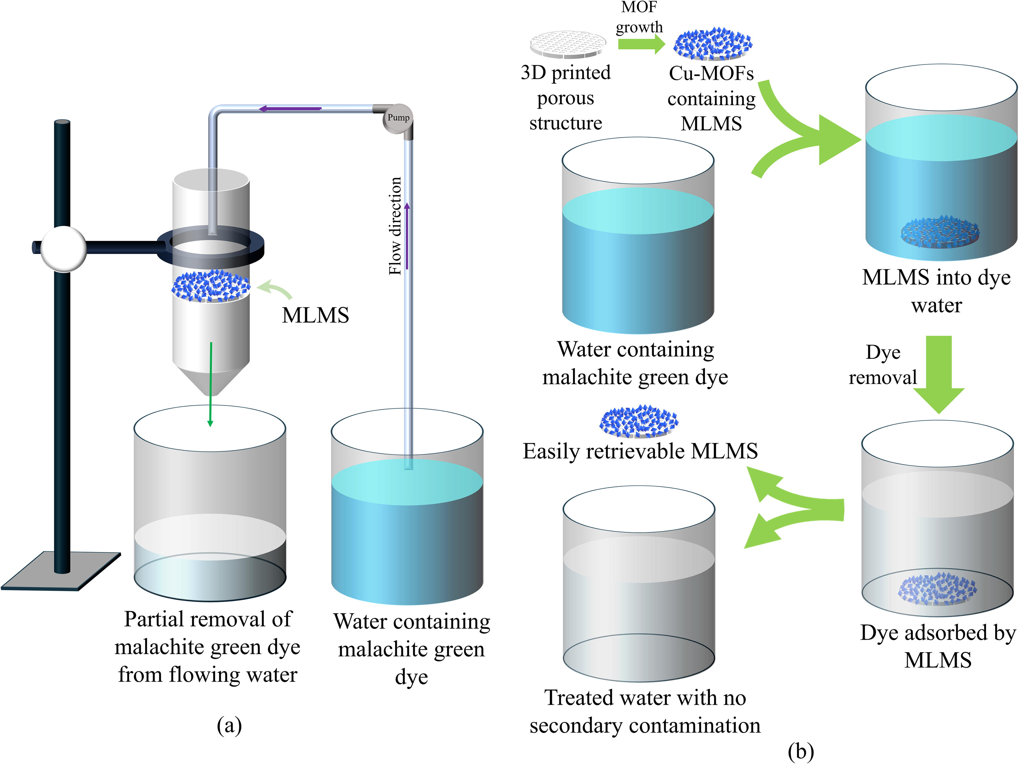
Schematic diagram of dye removal set-up from
Characterization
The optical images of the 3D-printed MLMSs with MOFs were taken by VHX 7000 Digital 4K microscope (KEYENCE Corp., IL). The X-ray diffractions of the MLMS before and after MOFs’ synthesis were done by X’Pert3 Powder X-ray Diffractometer, and the topography was analyzed by scanning electron microscopy (SEM, Zeiss NVision 40 FIB/SEM). The Fourier transform infrared spectroscopy (FTIR) was performed on the MLMSs before and after MOFs’ synthesis and only Cu-MOFs without any hosts using a Perkin Elmer FTIR-attenuated total reflectance spectrometer (Spectrum Two, PerkinElmer, Shelton, CT). The optical images were then analyzed with the ImageJ software by thresholding method for the area measurement. Images were taken at 3–5 different random locations using same settings zoomed at the same level (Fig. 3). The MOFs were detected from the intensity variation as shown in Figure 3, and the area covered by the MOFs was measured. Table 2 represents the quantitative data of the process.

Measurement of area covered by the MOFs.
Area Covered by MOFs on the MLMSs
MLMSs, MOF-laden monolith 3D structures; MOFs, metal-organic frameworks.
Results and Discussions
Characterizing MOFs and the host structures pattern for MOF growth
Highly crystalline Cu-MOFs were synthesized on the MLMS surface as demonstrated by SEM images in Figure 4(a). The XRD (X-ray Diffraction) spectra of the PLA host surface with and without Cu-MOFs are shown in Figure 4(b). Peaks observed at 11.5°, 19.4°, 21.1°, and 22.8° from the MLMS made of PLA with Cu-MOFs correspond to (222), (440), (620), and (551) planes. These peaks also confirm the presence of Cu-MOFs as they resemble the peaks for Cu-MOFs reported in the previous literature.29B30 -32 As the MOFs were on the host made of PLA, the XRD spectrum for the PLA can also be observed here. Due to the very small size of Cu-MOFs compared with the MLMS, the peaks generated by them were also weaker.

Morphology and characterization of Cu-MOFs.
The FTIR spectra of different MLMS with Cu-MOFs and only Cu-MOFs without the hosts are represented in Figure 5. In the case of PETG [Figure 5(a)], the peak at 1715 cm−1 displays the C = O of ester groups, and the C–H out-of-plane deformation of two carbonyl substituents on the aromatic ring depicts at 726 cm−1. The two peaks at 1409 and 1245 cm−1 are ascribed to the –CH2– deformation band and C(O)-O stretching of ester groups, respectively. The peaks attributed to C–H stretching for the presence of methyl groups in the structure of PETG are observed at 2853 cm−1 and 2928 cm−1. The C–H stretching peak of the cyclohexylene ring is found at 956 cm−1. 33
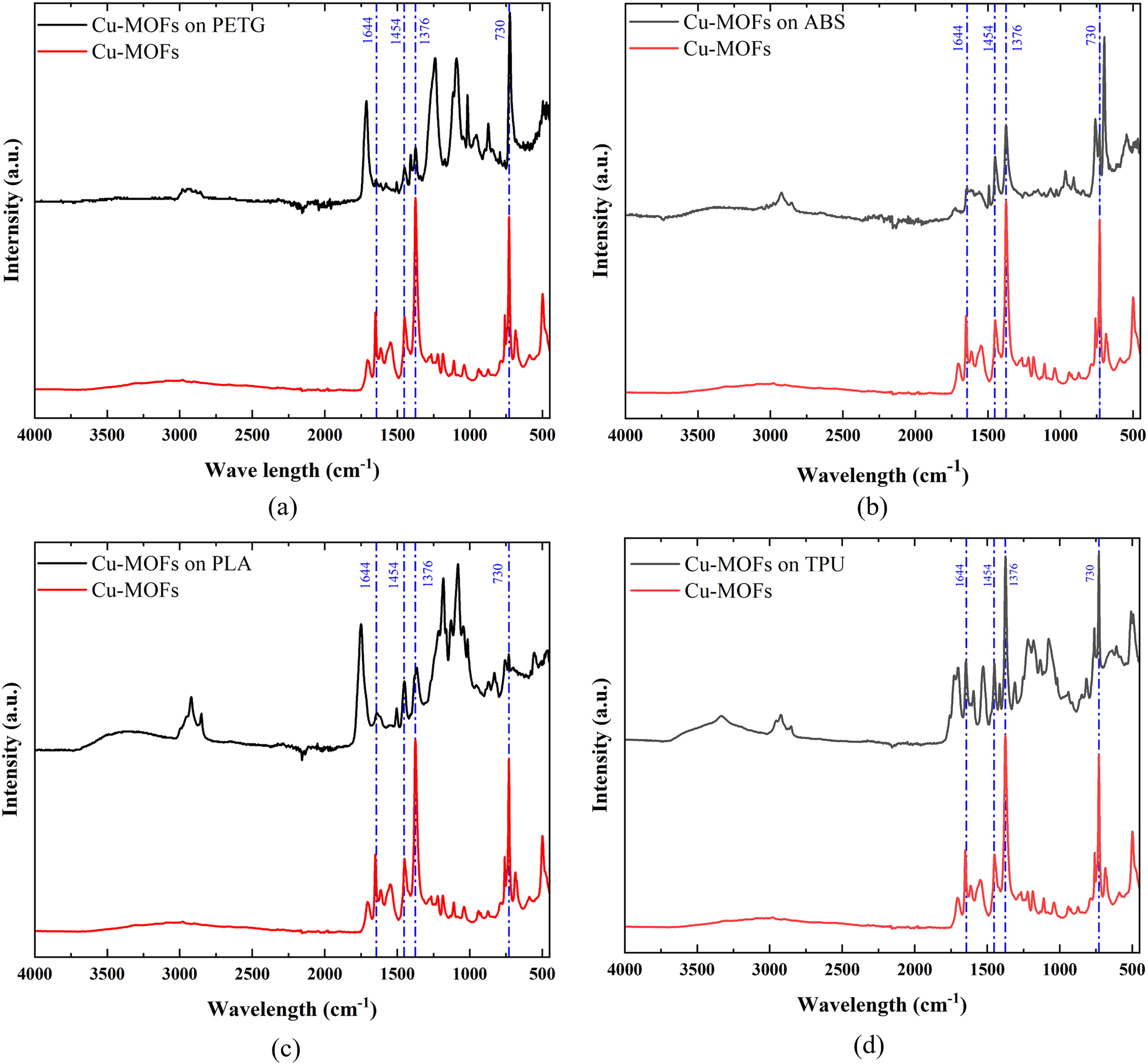
FTIR analysis of different hosts without and with Cu-MOFs.
Similarly, peaks from different bonds are presented in Figure 5(b–d) for MLMSs made of ABS, PLA, and TPU printing materials, respectively, with Cu-MOFs and only Cu-MOFs without the hosts.34B35 -39 The same Cu-MOFs’ FTIR peaks are visible in all four hosts as all of them carry the same MOFs [Figure 5(a–d)]. The peaks obtained at 730, 1376, 1454, and 1644 cm−1 represent the bending and stretching modes of Cu-O, the stretching mode of C-O, and asymmetrical and symmetric types of C = O, respectively, which resemble with the previously reported works. 40 It can be observed that the spectra generated from the Cu-MOFs containing MLMSs made of different materials showing the common peaks related to the Cu-MOFs are similar to the ones reported in previous works. 40 This indicates the successful formation of Cu-MOFs on all MLMSs.
The MLMS with a 90° raster angle forms a uniform grid-like Moiré pattern that is suitable for keeping the flow steady. Whereas a 5° raster angle MLMS offers a denser pattern with increased interference zones, which increases the surface complexity of the host for MOF growth. At a smaller air gap pattern (e.g., 0.4 mm), denser Moiré fringes can be observed for which the unit cell density and surface area get increased, while larger gaps (e.g., 0.7 mm) produce sparser patterns with fewer features as nucleation sites. Due to their geometric variation, slightly more MOF coverage can be observed with 5° raster angles compared with 90° till 0.6 mm air gaps as shown in Table 2. At 0.7 mm air gap, a reverse trend can be observed as the coverage decreases because of the wider spacing among the raster and the reduction of Moiré fringe density.
Figure 6 illustrates the optical images of MLMS produced from PLA containing Cu-MOFs following the completion of various synthesis cycles. Increased area coverage was achieved by synthesizing cycles being more frequent. At an angular pattern grid (5° raster angle), an increased number of interference zones enabled by thicker Moiré fringes resulted in higher nucleation sites and improved deposition, hence generating more coverage. This might affect the adhesion of MOFs to the MLMS substrate under flowing water, as higher tortuosity could increase the likelihood of MOFs’ detachment or leaching due to shear forces. A 90° raster pattern offers a simpler structure that can enhance the mechanical integrity of both the host and the MOFs under continuous flow. This durability may ensure that the MLMS retains its adsorption efficiency over time without frequent MOFs’ loss.

Optical images of PLA-printed Cu-MOF-synthesized MLMSs with 0.6 mm air gaps and (
Since the MLMSs were designed for high volumetric water contaminant remediation, the ease of water flow through them would be significant in determining the suitable pattern. To assess the applicability of the MLMSs to remove MG from both stagnant and flowing water, the change in permeability of the patterns was analyzed with the variation of p and α. The permeability (k) of the MLMSs can be calculated using the following equations:
41
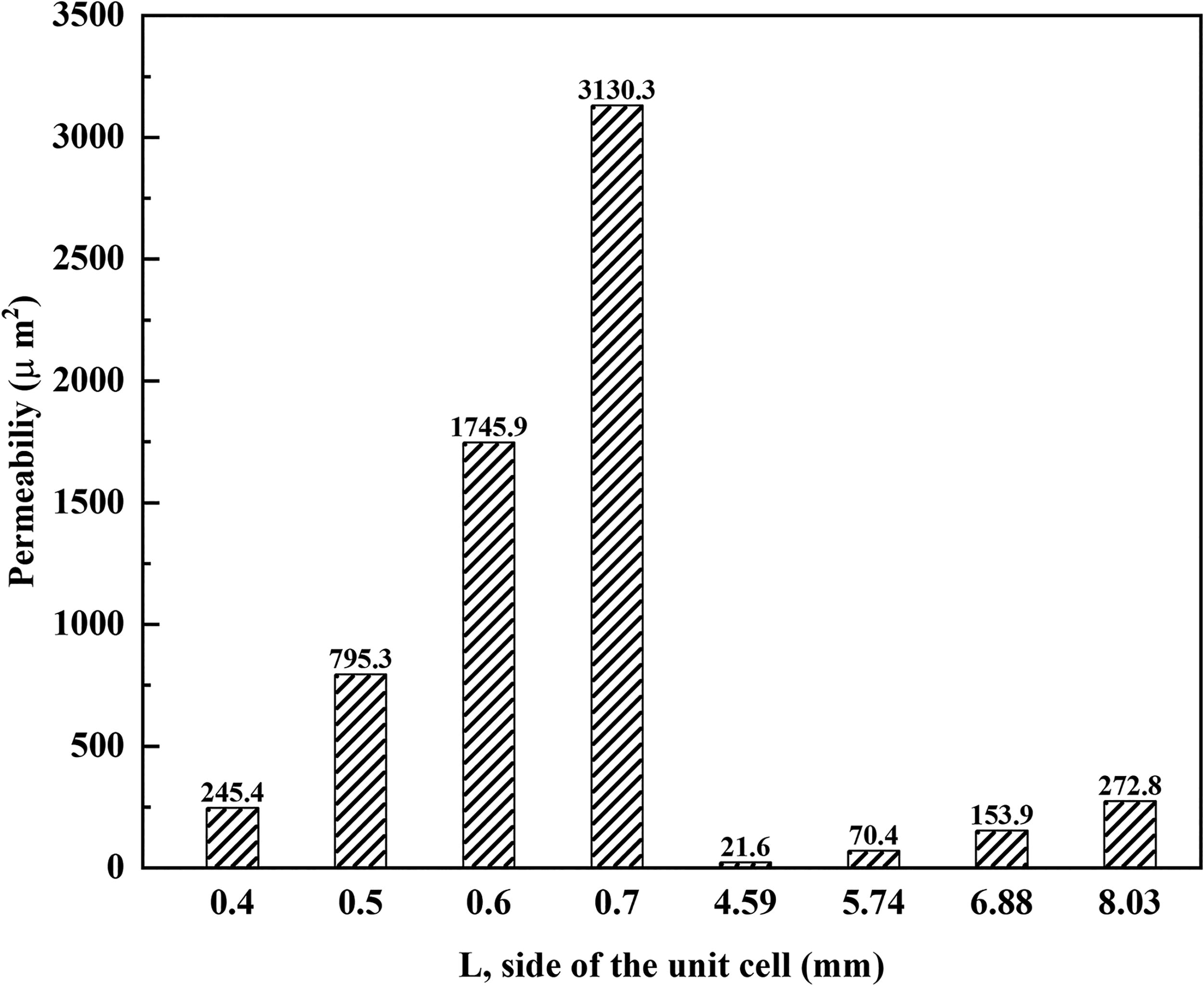
Change of permeability with the change in the length of the side of a unit cell of the different Moiré pattern.
Figure 7 depicts that MLMS with perpendicular (90°) grids shows higher permeability than angular (5°) grids due to their uniform patterns and lower raster density. Higher raster density at 5° angles impedes water flow, reducing permeability. Increasing the air gap reduces raster density, easing flow, while smaller gaps increase density, decreasing permeability. The 90° pattern, especially with 0.6 mm air gaps, offers optimal conditions by balancing flow ease and sufficient interaction time for effective MG adsorption, as its uniform structure minimizes turbulence and enhances permeability. Although the permeability of water through the MLMSs is important for the access of the dye water to easily reach the active site for interaction between the adsorbate and adsorbent, it should also be made sure that they get enough time for the interaction between themselves. Therefore, the MLMS with the 90° raster angle and 0.7 mm air gap demonstrating the highest permeability is good for allowing the water to pass through easily, but it may not be able to avail enough time for interaction between the water and the adsorbent. Conversely, MLMS with a 0.4 mm air gap can avail more interaction time but has high raster density which leads to low permeability. Considering both the permeability and available time to interact with MG for adsorption MLMSs with 90° raster angle and 0.5 mm or 0.6 mm air gap can be better options. As the attainable area covered by MOFs was the maximum and its uniform grid-like structure minimizing turbulence, ensuring smooth flow, and its better permeability enhancing dye contact suitable for the adsorption with MOFs, the pattern with 0.6 mm air gap and 90° raster angle was selected for this study. This design uses a repeating square-like lattice to maximize MOF coverage and dye contact, making it suitable for both stagnant and flowing water applications. The Moiré period is calculated as D = 0.42 mm (Equation 2), and each cylindrical MLMS has a 25.4 mm outer radius and thicknesses of 3 and 12.7 mm.
Growth mechanism of MOF on MLMS
The growth process of Cu-MOFs on the host mainly involves immersion of the host in H3BTC and TEA solution followed by its exposure to a copper (II) nitrate solution. In this reaction, TEA acts as a deprotonating agent, 42 neutralizing the carboxylic acid groups on H3BTC, forming benzenetricarboxylate anions (C9H3O6³−). The negatively charged C9H3O6³− may begin to loosely bind to the host surface via noncovalent interactions (e.g., hydrogen bonding or van der Waals forces) or weak covalent bonds and start to attach onto the surface of the host. This forms a layer of ligand molecules on the host surface, which will serve as nucleation sites for the Cu-MOFs’ formation in the next step.
C9H6O6 (H3BTC) + N(CH2CH3)3 (TEA) → C9H3O63− (benzenetricarboxylate) + 3 (TEA-H)+ 3 Cu(NO3)2 + 2 C9H3O63− → [Cu3(C9H3O6)2] + 6NO3−
In the second step, the functionalized host was immersed in a solution of copper (II) nitrate in ethanol–DI water solution. The copper (II) ions (Cu2+) from copper (II) nitrate coordinate with the carboxylate groups, which lead to the formation of Cu-MOFs on the MLMS.
The effect of heat treatment on the MOFs’ adhesion
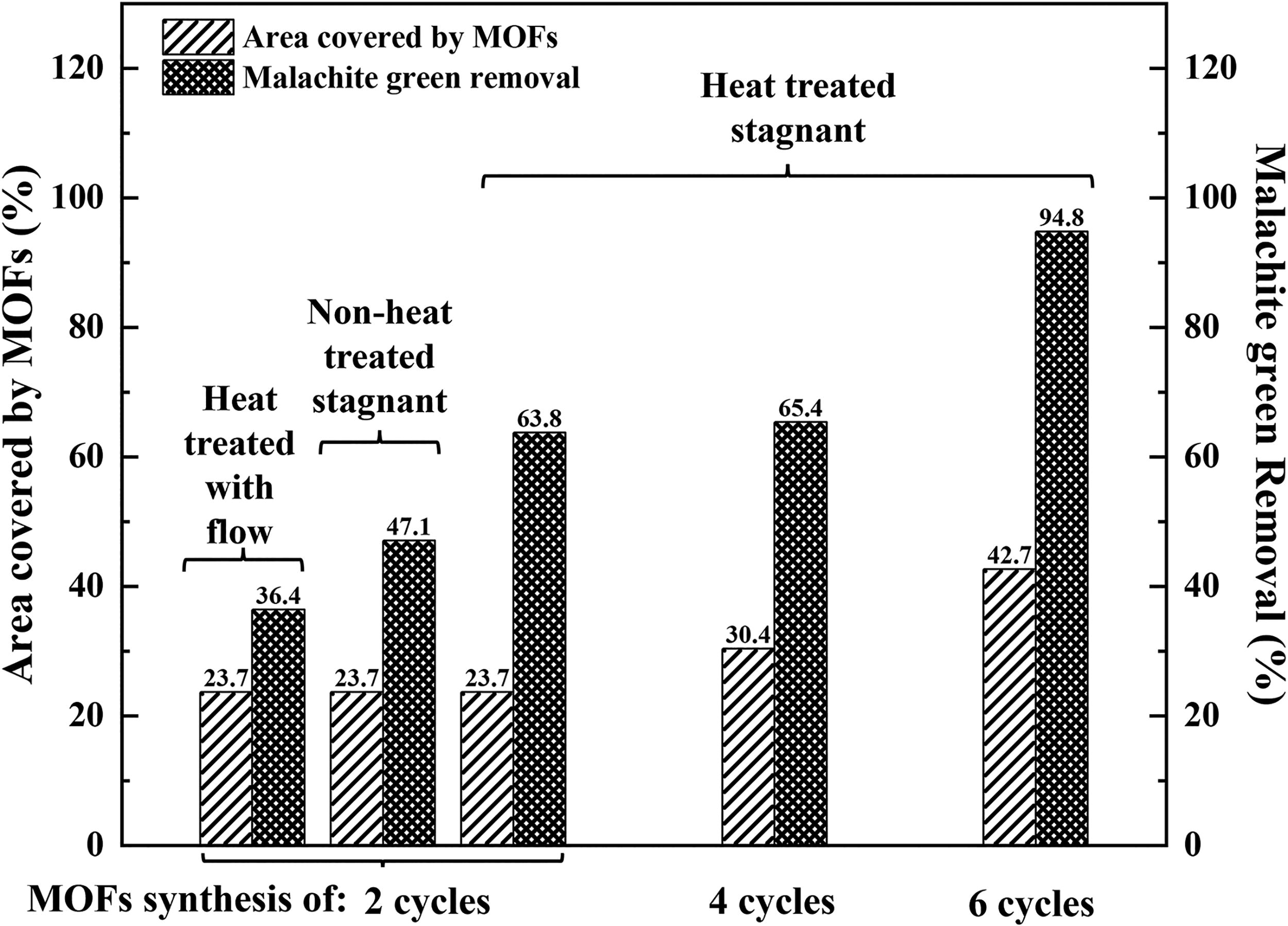
To increase the adhesion between MOF and the host substrate, the MLMS structures were heat treated at or around the glass transition temperature of the host material. Table 3 shows that the surface area covered by MOFs decreased significantly from 21.9% to 3.75%, resulting in an 82.9% drop, attributable to the flow of 4.14 × 10³ L m−2 h−1 on the unheated MLMS made of PLA. With the heat treatment, the area occupied by the MOFs decreased from 29% to 24.3%, reflecting a 16.1% drop in area relative to the original coverage. Furthermore, the MLMS was utilized in stagnant water containing 1 mg/L MG for 2 h, resulting in a decrease in area coverage from 24.2% to 23.2% (a reduction of 4.21%) for heated MLMSs, and from 19% to 9.06% (a reduction of 52.3% compared with the initial coverage) for unheated MLMSs with MOFs.
Changes in MOF Coverage at Different Flow Rate with and Without Heat Treatment
MOFs, metal-organic frameworks.
Heat-treated MLMSs consistently exhibited greater MOFs’ coverage under flow in comparison with unheated MLMSs. This indicates that heat treatment improves the adherence of MOFs to the hosts. MOFs’ coverage decreased across all situations upon exposure to flow, indicating a material loss attributable to the mechanical stress induced by the fluid dynamics. Heated MLMSs had a reduced percentage of area change relative to unheated MLMSs, indicating that the enhancements in the resistance to mechanical stress took place due to the heat treatment. Heating MLMSs at the glass transition temperature increases MOFs’ adhesion and improves the durability of the MOFs layer under dynamic settings, hence minimizing coverage loss over time. Polymer (PLA) becomes flexible and functional groups become active, increasing the adhesion potential when heated close to its glass transition temperature. As the polymer becomes more pliable, MOFs may integrate deeper into the polymer, while increasing the contact area and improving the mechanical adhesion of the MOFs to the surface.
The detachment or leaching of the MOF from the MLMS surface under water flowing at 4.14 × 10³ L m−2 h−1 had been studied to investigate the adhesion strength between the MOF and MLMS. This flow rate is much higher (>40 times) than commonly used household drinking water filtration device. The results indicate that heat-treated MLMS samples exhibit significantly improved adhesion of Cu-MOFs to the polymeric host surface, with only a 16.1% reduction in MOF surface coverage at a high flow flux of 4.14 × 10³ L m−2 h−1, compared with an 82.9% loss in untreated samples. This substantial difference highlights the critical role of heat treatment in enhancing the interfacial bonding between MOFs and the polymer. The improved adhesion is attributed to increased polymer chain mobility near the glass transition temperature during heating, which likely allows MOFs to partially embed into the polymer surface and establish stronger physical and chemical interactions, such as hydrogen bonding and π–π stacking. Although some MOF detachment under flow conditions remains unavoidable, the reduced leaching observed after thermal post-treatment suggests that the adhesion strength is adequate for practical use in short-to-medium duration filtration scenarios. In addition, by adjusting certain structural parameters, such as the thickness and pattern design of the MLMS, and varying the number of MOF synthesis cycles, it may be possible to determine optimal conditions for achieving reduced leaching along with higher dye removal efficiency. To further improve stability, future approaches may incorporate chemical surface modifications such as plasma treatment or functional group grafting to promote covalent bonding at the interface. In practical implementation, any leaching may affect long-term filtration efficiency and raise environmental safety concerns. Therefore, system designs that incorporate thicker MLMS layers or multiple filtration units in series may mitigate these effects by compensating for MOF loss while maintaining performance.
The effect of different 3D printing materials on MOFs’ growth
The growth of Cu-MOFs on the hosts manufactured using different 3D printing materials was different depending on which materials they were made of. Figure 8 presents the variation in the percentage of area covered by the MOFs on various MLMS hosts.
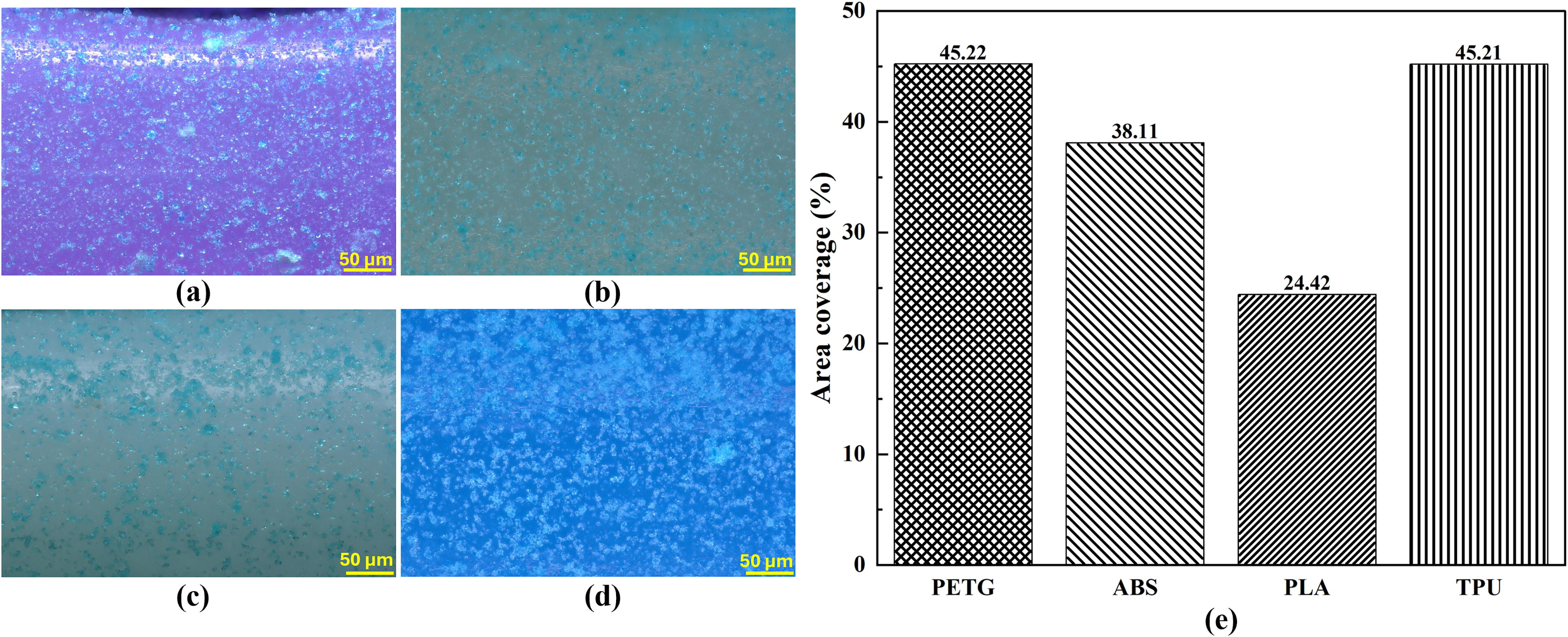
Area coverage of the MOFs on different hosts after two cycles. Optical image of Cu-MOFs on
Two cycles of Cu-MOFs’ synthesis were performed on each type of material host. The area covered by the MOFs depends on the polarity, hydrophobicity, and hydrophilicity or wettability of the printing material and the nucleation of crystals or growth of the MOFs. Crystal nucleation is related to the number of active sites and the functional group available in the material. For further investigation, the wettabilities of the different printing materials were compared, and the contact angles formed by water on the surface of the MLMS hosts made of PETG, ABS, PLA, and TPU were reported as 46.6°, 50.2°, 56.4°, and 64.1°, respectively. 43
The growth of the Cu-MOFs on the MLMSs is influenced by surface properties like the hydrophilicity of the host materials. For example, MOFs’ growth is aided by the hydrophilicity and surface properties of PETG, which can facilitate nucleation sites for the MOFs due to its functional groups and interactions with solvents like ethanol and water.44,45 During the synthesis of MOFs, the PETG host is typically exposed to H3BTC and TEA, which activates carboxyl groups. This carboxyl group coordinates with copper ions in the later phase. When this host is subsequently placed in a copper nitrate solution, the metal ions coordinate with the carboxylate groups on the benzene rings to form the Cu-MOFs. As the MOFs develop, they grow along the host surface, and due to PETG’s surface properties, they can adhere and extend as a stable coating. Compared with other host materials, PETG’s slightly polar and functionalized surface makes it favorable for Cu-MOFs’ growth, likely resulting in more uniform coverage and stability. This affinity is rooted in PETG’s balanced hydrophilic/hydrophobic character, which supports better linker interactions compared with nonpolar materials like ABS or more hydrophilic ones like TPU. PLA’s lower coverage of the PLA host may be due to its rigid structure and limited stability under synthesis conditions. PLA’s surface degradation under prolonged solvent exposure can reduce the efficacy of MOFs’ attachment, resulting in lower area coverage compared with PETG.
The effect of different 3D printing materials on adsorption
The Cu-MOFs grown on different hosts resulted in different MG removal performances. The removal rates achieved by Cu-MOFs synthesized after two cycles on PETG, PLA, ABS, and TPU hosts were 63.75%, 13.37%, 11.51%, and 5.66%, respectively [Figure 9(a)]. The optical images of the MLMSs made of various materials are presented in Figure 9(b–e). The experimental set-up for dye removal from stagnant water and flowing water is demonstrated in Figure 9(f and g), respectively. The visual comparisons of the removal performances have been illustrated in Figure 9 (h–k).
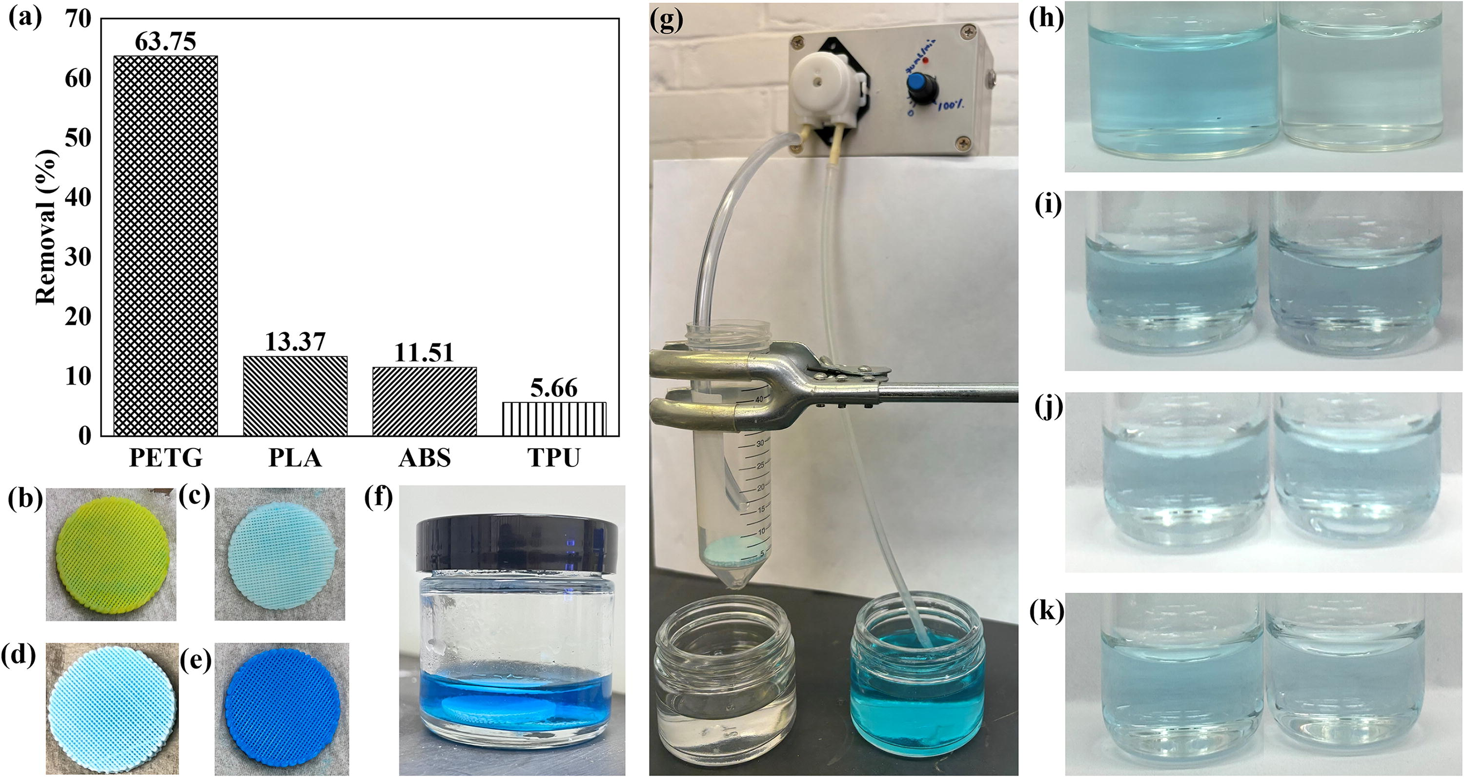
Dye removal performance of Cu-MOF-based MLMS.
Adsorption of dyes by any adsorbate generally involves mechanisms like electrostatic interactions, π–π stacking, and hydrogen bonding. The compatibility of PETG with Cu-MOFs enhances these interactions, thus increasing MG adsorption. However, PLA, TPU, and ABS provide less favorable chemical interactions, limiting adsorption capacities due to reduced surface activity and pore misalignment with MG size. 46 PETG, with its relatively high hydrophilicity and chemical stability, can not only enhance Cu-MOFs’ growth and distribution but also improve the active surface area for MG adsorption. This characteristic contributes to better adsorption performance compared with PLA, ABS, and TPU, which may provide weaker adhesion and distribution for MOFs, limiting their adsorption efficiency for MG.23,46 PETG, as reported in previous research, can support well-distributed Cu-MOFs with microporous structures that match MG’s dimensions, allowing efficient capture. In contrast, hosts made of PLA and TPU may produce less ideal MOFs orientations, reducing surface exposure and pore accessibility for MG molecules.23,46 The adsorption efficiency of Cu-MOFs for MG on different substrates is also largely influenced by the polarity and charge characteristics of each host, which affect the MOF’s attachment, dispersion, and interaction with MG.
PETG is relatively polar and hydrophilic compared with the other materials, which supports Cu-MOFs’ adherence and uniform distribution. This polarity aligns well with MG’s positive charge, facilitating strong electrostatic attractions and π–π interactions between MG’s aromatic rings and the Cu-MOFs on PETG, thus achieving higher adsorption efficiency. PETG’s polarity also enhances its wettability in aqueous solutions, which can help in distributing the Cu-MOFs more uniformly across the surface, optimizing exposure to MG molecules.46,47 The removal efficiency of the MLMS manufactured from PLA is lower than that of PETG because the less flexible structure of PLA can hinder MOFs’ distribution, reducing surface area availability for MG interaction. The weak electrostatic interaction between MG and TPU due to the lack of polarity TPU and its hydrophobic nature may limit its compatibility with aqueous MG solutions, reducing adsorption potential in the case of MLMS made of TPU. 46 Like TPU, ABS, low polarity does not support strong electrostatic or π–π interactions with MG, yielding low adsorption efficiency by the ABS-made MLMS. 47 Therefore, PETG’s higher polarity and hydrophilicity support optimal MOF growth and MG interactions, while PLA offers limited compatibility. TPU and ABS have the lowest efficiencies due to their hydrophobicity and weaker polarity, which reduces both MOFs’ attachment and interaction with the cationic MG.
MG removal by Cu-MOFs hosted on PETG from stagnant water
As the host material of MLMS, PETG has exhibited the best compatibility for enhancing the MG removal performance. Therefore, feasibility study efforts have been centered on PETG as the host material. The MG removal efficacy is influenced by various synthesis parameters and conditions. To achieve the optimum removal performance, the effects of variation in the number of synthesis cycles and post-heat treatment have been studied.
A higher number of synthesis cycles directly correlate with increased MOFs’ coverage on PETG, creating a larger surface area with active sites for MG adsorption. Each additional cycle results in increasing the density and accessibility of adsorption sites, which optimizes the MLMS’s capacity to adsorb even more MG molecules. From Figure 9, it can be observed that PETG with six cycles achieves higher MG removal (94.77%), demonstrating that high cycle counts optimize MOFs’ growth and coverage, thereby enhancing adsorption efficiency.
The FTIR peaks (c.f. Fig. 5) of the MLMS containing Cu-MOFs confirm the presence of the Cu-MOFs after the heat treatment, indicating that their structures remain intact despite going through the heat treatment. Heat treatment as an optimization factor stabilizes the MOFs’ structure, enhancing crystallinity and surface area. Furthermore, heat-treated MLMS made from PETG and containing MOFs synthesized in two cycles performs significantly better than unheated ones (63.75% vs. 47.06%), underscoring that heat treatment is essential in improving the MOFs’ stability, their adhesion to the host, and adsorption potential under prolonged conditions.
The remediation of MG by PETG-MLMS from flowing water
The flow of water has also been introduced to study the effectiveness of this system in real-life applications. In this case, the thickness of the MLMS host has been increased to allow the MG-containing water to have more time to interact with the MOFs for efficient removal performance. The thickness was adjusted from 3 mm to 12.7 mm, and the number of MOFs’ synthesis cycles was kept at 2. The host material of MLMS used in this part of the study was limited to PETG. As PETG as a host material exhibited the best MG adsorption performance from stagnant water, its application in flowing water was explored at the flow flux (
Comparative representation of removal performance at different synthesis parameters and conditions.
Remediation of MG from the flowing water using MLMS hosting Cu-MOFs was measured to be 36.42%. Under flow conditions, the relatively reduced contact time between MG and MLMS may have likely decreased the adsorption efficiency compared with stagnant conditions, where contact time is maximized. This removal rate can be increased by scaling up the set-up with a series of filters, which can be the future work. In addition, thicker MLMSs can be used for increasing the removal rate. However, the uniform MOF growth in the internal region with the increase in MLMS thickness may need to be optimized.
Adsorption and adhesion in MLMS and comparative studies
The adsorption of MG by the MLMS made of PETG can be attributed to the interactions taken place between the Cu MOFs and MG (Fig. 11). Electrostatic interactions, hydrogen bonding, and the π–π stackings are reported to be the major contributing factors in MG adsorption. 14 The electrostatic interactions may take place between the positively charged nitrogen of MG and the negatively charged oxygen ions of the Cu MOF. The hydrogen atom of Cu MOF and dimethylamino, −N(CH3)2, group of MG can form hydrogen bonds, whereas the π–π stacking interaction can be observed between the benzene rings of MG and Cu MOFs. It was reported that the size of the molecules of the dyes and the pore sizes of the adsorbents can influence the adsorption performance. 46 If the sizes are similar, the adsorption capability of the adsorbent is high. It was observed that the MG with the particle size of about 2 nm was best adsorbed by the Cu-MOFs-2, which had the pore sizes of 2.11 nm. Therefore, a similar advantage of matching the pore size and molecule size may prevail in the case of the removal performance of MG using our Cu-MOFs.
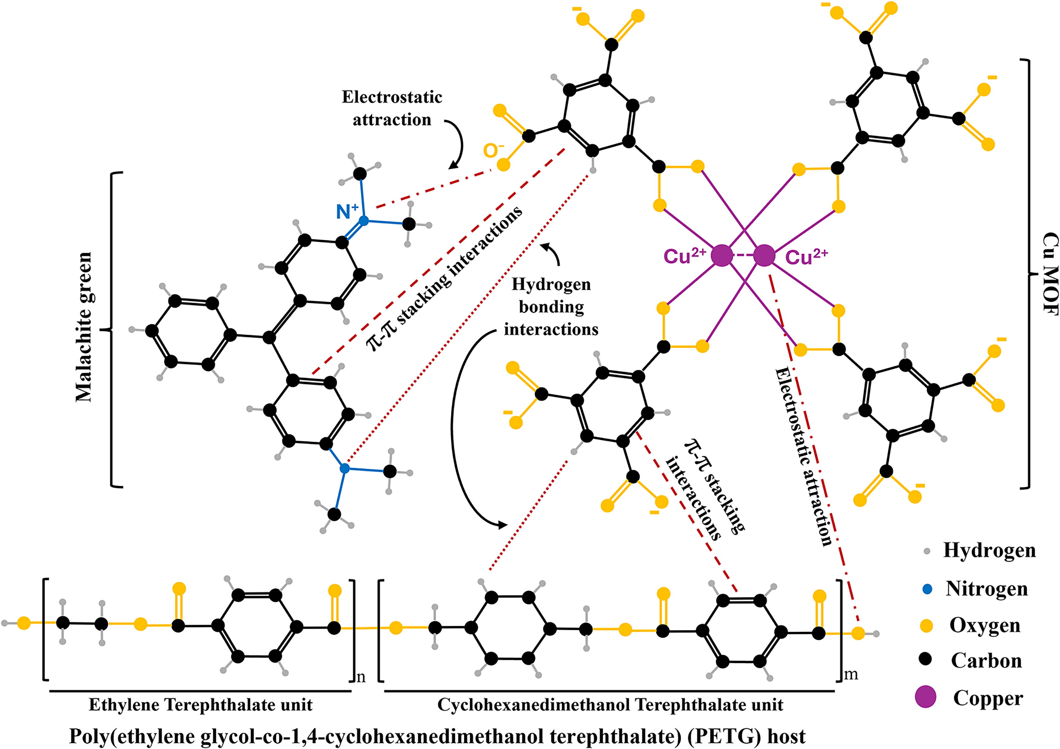
Schematic diagram of adsorption of MG by the Cu-MOF and adhesion between the PETG host and Cu-MOF. Cu-MOF, copper-based MOF; MG, malachite green; PETG, polyethylene terephthalate glycol.
Similarly, the adhesion between the PETG-printed host and the Cu-MOF can be analyzed by the interactions developed between them. PETG, also called Poly(ethylene glycol-co-1,4-cyclohexanedimethanol terephthalate), has two repeating units. Those are cyclohexanedimethanol terephthalate and ethylene terephthalate. The hydrogen bonding may develop between MOF and PETG. 48 The π–π stackings may develop between the terephthalate units of PETG and benzene rings on the Cu-MOFs. 48 The electrostatic interaction can occur between the Cu2+ ions of the Cu MOF and the oxygen ions of the PETG. As a result, the MOFs get attached on the host surface making MLMS. The comparative adsorption performance of MG by different adsorbents can be summarized in the following table.
Table 4 shows that the MG removal efficiency of the MLMS developed in this study surpasses that of previously reported similar composites, such as Cu-MOFs/PLA. While some adsorbents have demonstrated higher removal efficiencies, those results were achieved through external modifications and specific operational conditions, making the processes more complex and less cost-effective. To the best of the authors’ knowledge, dye removal from flowing water has not been previously reported. Therefore, greater attention may be directed toward enhancing adsorption performance under flowing water conditions in our future work.
Adsorption Efficiencies of MG by Different Adsorbents
Cu-MOF, copper-based MOF; MG, malachite green; PLA, polylactic acid.
Conclusion
This study successfully demonstrates the development of a scalable and effective 3D-printed filtration system integrating Cu-MOFs into MLMS structures, presenting a promising approach to advanced water purification. The highest Cu-MOFs’ growth was found on PETG host among different polymeric host materials owing to its superior hydrophilicity and stability. In addition, the incorporation of a Moiré pattern design with a 0.6 mm air gap and perpendicular pattern significantly enhanced the surface area for Cu-MOFs’ growth while maintaining structural integrity. Heat treatment proved essential for improving the mechanical adherence of Cu-MOFs, reducing leaching, and enhancing system durability under continuous flow conditions. By combining these exceptional properties of MOFs with the precision of 3D printing, the Cu-MOFs@PETG achieved notable removal efficiencies of 94.77% in stagnant conditions and 36.42% under dynamic flow conditions, offering a viable alternative to traditional filtration methods that often struggle with microcontaminants. The precise geometrical design using the Moiré pattern makes these MLMSs both functional and visually inspectable, aligning with advancements in microfiltration. This research underscores the potential of MLMS-based filtration systems as adaptable and efficient platforms for addressing diverse pollutants in various water treatment scenarios.
Footnotes
Acknowledgments
The authors would like to acknowledge Zafir Bashir, a summer high school student, for his assistance with 3D printing the samples used in this project. The authors would like to thank Dr. Mehdi Tajvidi and Rakibul Hossain for allowing them to use the FTIR equipment for the analysis of the sample and for their invaluable assistance and support in operating the equipment.
Authors’ Contributions
A.Z. was responsible for methodology, writing the original draft, and creating visualizations. S.C.A. validated experimental procedures and reviewed and edited the article. B.K. conceptualized the research, administered the project, and revised and edited the article.
Author Disclosure Statement
No competing financial interests exist.
Funding Information
No funding was received for this article.