
Abstract
Multi-material direct ink writing (M-DIW) is an advanced additive manufacturing technology capable of fabricating complex soft polymeric structures. However, material switching during M-DIW presents challenges such as switching lag and coextrusion, which significantly affect printing accuracy and fidelity. To address these issues, this study develops an M-DIW system integrating a pneumatic extrusion control system and a multichannel printhead, enabling material switching during printing. To enhance printing performance, a flow rate–pressure model is established to analyze ink extrusion dynamics, and a static ink pre-extrusion control strategy is proposed to minimize switching lag while mitigating coextrusion effects. Experimental validation demonstrates that the proposed method effectively improves material switching precision, ensuring high-resolution multi-material printing. Multiple printing case studies, including checkerboard patterns and functional soft structures, confirm that the system can achieve rapid material switching during printing while ensuring sharp material boundaries. This research provides an optimized method for M-DIW printing, broadening the scope of complex soft structures that can be designed and manufactured.
Introduction
Multi-material direct ink writing (M-DIW) has garnered widespread attention due to its high material tolerance and strong method scalability, allowing for the straightforward completion of multi-material integrated forming tasks. Skylar-Scott et al. 1 developed a multi-material multi-nozzle 3D (MM3D) printing system to achieve continuous co-printing of high-precision 3D voxelated structures, successfully printing foldable structures and crawling soft robots as exemplars. Hassan et al. 2 utilized an M-DIW system to successfully print pneumatic bending fingers capable of being assembled into soft grippers. Schaffner et al. 3 printed various soft actuators capable of performing multiple actions, such as twisting and grasping, based on the principle of fiber-induced structural anisotropic shrinkage through M-DIW.
M-DIW imposes stringent requirements on material extrusion control and printhead design. To achieve faster response times and more precise pressure control, M-DIW often opts for pneumatic extrusion methods.1,4,5 Some studies have adopted extrusion mechanisms utilizing motors and mechanical transmission systems to gain advantages in terms of cost and miniaturization.6,7 Printhead configurations include separate multi-nozzle setups and multichannel printheads, with the latter being predominantly employed in current M-DIW technologies.8,9
However, the complex nature of viscoelastic inks poses significant challenges to the print control of M-DIW. Ober et al. 9 designed an actively mixed microchannel printing system that allows for the real-time mixing of two-component inks, thereby avoiding time constraints imposed by the printing window. Walker et al. 10 delved into the curing kinetics of inks, determining the moments of maximum curing rate and the complete curing time after the ink matrix is mixed with thickeners, to guide the printing process. Shao et al. 11 investigated the conformality of printed filaments and the selection of printing parameters by establishing ink flow models and filament cross-section models. In summary, besides configuring appropriate material components and adjusting material rheology, optimizing system configurations and printing parameters is also a crucial approach to enhancing M-DIW printing performance. However, during actual printing, the extrusion and switching of printing inks in the flow channels are affected by factors such as viscous forces and material compressibility, leading to problems such as nozzle clogging, significant switching lag, and severe coextrusion, which severely impact the quality and precision of multi-material printing.
This article designs and develops an M-DIW system. The system integrates a multichannel printhead and a pneumatic extrusion control system, enabling seamless switching between two inks during printing. To address the problems of switching lag and coextrusion in multi-material printing, this article models the extrusion process of the inks and proposes a static ink pre-extrusion control method based on the ink’s flow rate–pressure model. This method effectively reduces the switching lag while controlling the coextrusion phenomenon, thereby optimizing the performance of multi-material printing. Finally, the effectiveness of the proposed method and the developed M-DIW system is validated through several sample prints.
System Design
Construction of the M-DIW system
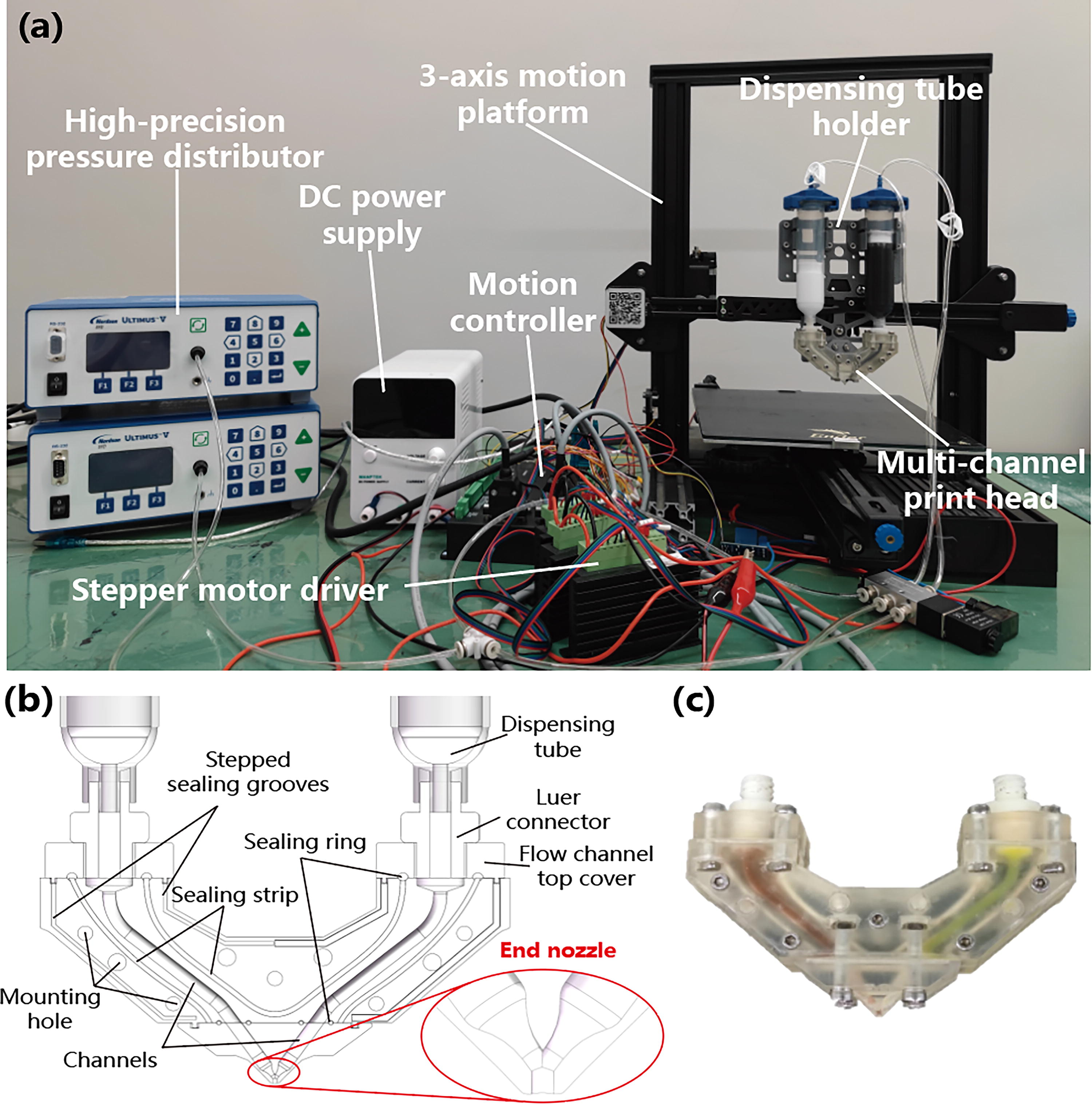
The fundamental components of the M-DIW system include a three-axis motion platform, a multichannel printing head, dispensing tubes and their holder, a pressure distributor, an air pump, a motion controller, and a computer, as shown in Figure 1a. In terms of the extrusion drive mechanism, the system employs a high-precision pressure distributor as the driving control source. The external pressure distributor used is the Ultimus V high-precision dispensing machine from Nordson Corporation. By regulating the pressure of two dispensing tubes through the dispensing machine, the M-DIW system enables high-precision, high-stability, and high-frequency response control of dual-material extrusion. Regarding control hardware, this study replaces the original control motherboard with the ZMC406 motion controller from ZMotion. The ZMC406 supports up to 32-axis motion control and features a refresh rate of up to 2 kHz. This study develops a system control framework based on the principles of sequential control. This framework is capable of executing G-code commands for print control.
The pneumatic extrusion-based M-DIW system:
Design of multichannel printing head
The printing head is primarily fabricated using transparent resin (Formlabs) via a VPP printer (Form 3+, Formlabs). Due to manufacturing precision constraints, the inner diameter of the end nozzle channel is 800 µm. In terms of assembly, the printing head adopts a modular design, consisting of five components: two upper covers, a two-part channel body, and a Y-shaped end nozzle, as shown in Figure 1b. The upper covers are equipped with Luer adapters, enabling the upper end of the channel body to connect with the dispensing tube via the Luer adapter, while the lower end is fitted with the Y-shaped end nozzle, forming a complete ink transport channel. The components of the printing head are primarily assembled using mechanical bolts. Nozzles of different sizes share the same mounting dimensions to ensure interchangeability. The modular design not only ensures the manufacturing precision of the internal flow channels but also facilitates disassembly for maintenance, such as cleaning residual ink within the channels. The end nozzle features a Y-junction, allowing two inks to share a common outlet, thereby enabling rapid material switching during printing.
The outlet section of the end nozzle has an extremely short channel length (1 mm) to minimize dead volume. The upstream channel has an inner diameter of 2.5 mm to reduce ink flow resistance. Sealing rings are installed at the contact interfaces between the channel body, the upper cover, and the end nozzle. Additionally, grooves are embedded along both sides of the flow channel path within the contact surface of the two-part channel body to accommodate sealing strips, ensuring a completely enclosed internal flow channel. Furthermore, the channel body incorporates stepped sealing grooves, where interlocking step features enhance assembly and further improve channel sealing performance. The assembled multichannel printing head is shown in Figure 1c.
Material
To validate the printing capability of the developed M-DIW system, this study selects polydimethylsiloxane as the primary printing material (silicone ink). The silicone ink used for printing is composed of SE1700 (DOWSIL), Sylgard 184 (DOWSIL), and Slic Pig dye (SMOOTH-ON). SE1700 and Sylgard 184 are two silicone elastomers with distinct rheological properties, and their mixing ratio affects both the fluidity and shear yield strength of the printed ink. In most cases presented in this study, the ratio of SE1700, Sylgard 184, and the Slic Pig is 7:3:0.1. Then the mixture is centrifuged in a planetary mixer (Marath MV-300) at −85 kPa and 1000 rpm for 2 min. The resulting mixture is then transferred into a dispensing tube, and the vacuum centrifugation step is repeated to remove air bubbles.
Printing Model Analysis
Analysis of printing performance issues
Material switching performance is a critical challenge in the M-DIW system. Figure 2b demonstrates the multi-material switching problem through an example of printing a grid pattern. Compared with the designed pattern (Fig. 2a), the switching positions of the printing materials exhibit significant lag. Furthermore, the material filaments contain two types of ink, making it impossible to observe complete white or black regions. Although the printing filaments can be continuously extruded and deposited during material switching, the pattern fidelity is severely degraded due to the problems of switching lag and coextrusion.

Printing issues and extrusion models.
The ink switching lag in M-DIW is primarily due to the fact that the new ink needs to first expel the old ink from the dead volume before it can be extruded. As shown in Figure 2c left, the dead volume mainly consists of three parts: the backflow segment of the dynamic ink, the ink convergence zone at the Y-junction, and the end nozzle segment. In designing the printhead, this study has minimized the volume of the convergence zone at the Y-junction and the end nozzle channel as much as possible.
If a sustained pressure is applied to the static ink to drive the interface between the two inks closer to the Y-junction, this can effectively reduce the dead volume but may lead to coextrusion. As illustrated in Figure 2c right, the convergence region of the two inks occurs within the Y-junction, where the dynamic ink carries partial static ink during extrusion, resulting in coextrusion of both inks. Figure 2d displays the experimentally captured phenomena of backflow and coextrusion. The switching lag and coextrusion problems in M-DIW printing present an inherent contradiction. The strategy adopted in this article involves temporarily tolerating the backflow of dynamic ink during extrusion while applying a modest pre-extrusion pressure to the static ink for a short period before material switching to extrude the backflow segment of the dynamic ink. Although this approach still causes limited coextrusion at the switching point, it effectively reduces switching lag while confining the coextrusion phenomenon specifically to the transition region.
Ink extrusion model
The inks commonly used in M-DIW typically exhibit shear-thinning behavior, meaning their viscosity decreases as the shear rate increases. This property facilitates the flow of ink through the nozzle, ensuring extrudability.
12
After extrusion, the viscosity of the ink quickly recovers in the absence of shear forces, ensuring sufficient structural support and adhesion to prevent shape collapse. Typically, DIW inks exhibit a viscosity drop to the range of 102–106 mPa under shear rates of approximately 0.1 s−1.13-15 Shear thinning is more pronounced in high-molecular-weight polymers and at higher polymer concentrations.
16
Such fluids are generally described by the Herschel–Bulkley (HB) model,17-19 including the inks used in this study:
In practical scenarios, the ink properties of thixotropic materials are influenced not only by the shear rate but also by the shear history.
20
Therefore, it is necessary to introduce a time-dependent correction to the HB model:
The flow of ink in a pipe is described as follows:
In addition, during the yield flow of the ink, the transient effects caused by the elasticity of the ink are relatively minor. Therefore, the model assumes that the printing ink is an incompressible fluid and that only isothermal processes occur within the system, thereby neglecting the influence of the energy equation. Based on the assumption of incompressible fluid, it follows that the ink undergoes a steady flow with constant density in the flow channel, that is,
For axisymmetric flow channels, the ink does not undergo circumferential motion under the axial pressure at the port, resulting in:
Substituting equations (5) and (6) into the continuity equation (3):
Based on the cylindrical coordinate system (Fig. 3a), the motion equation (3) for the fluid in the pipe is expanded, and the boundary conditions (4), (5), and (6) are incorporated, allowing the following function to be derived:
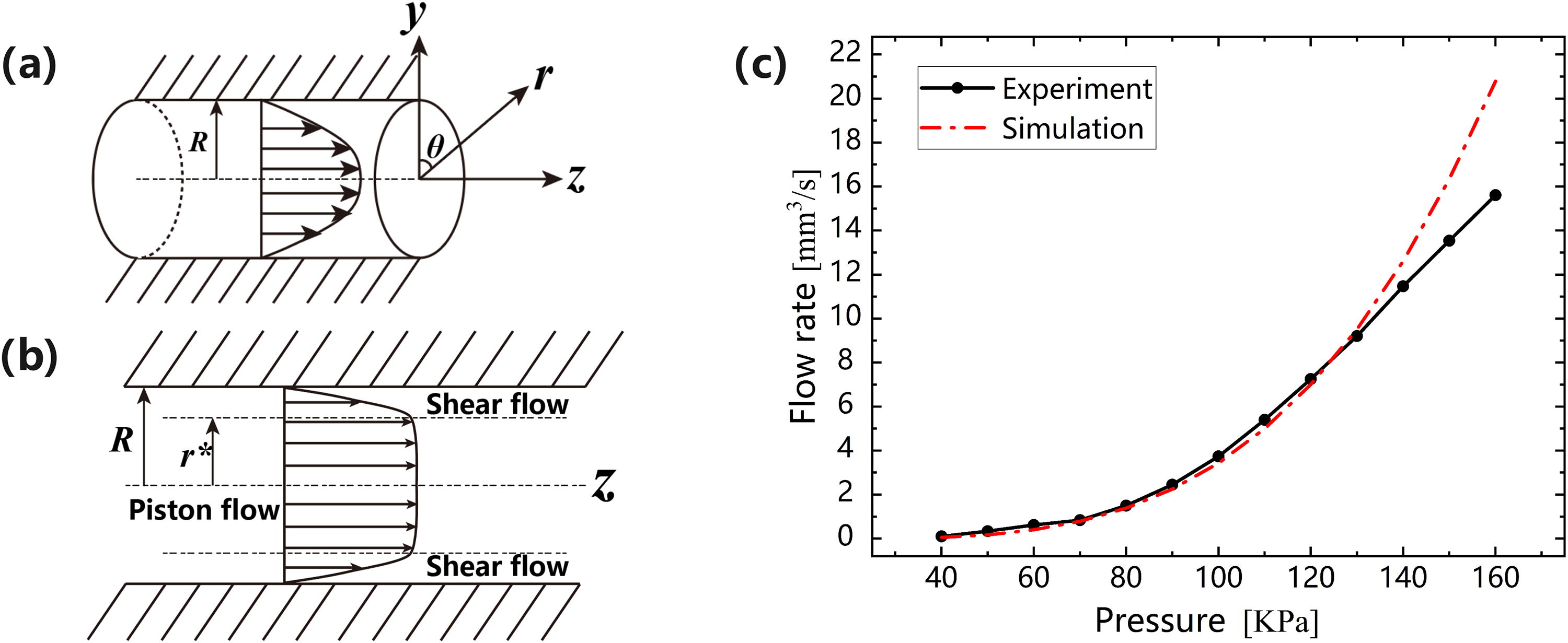
The flow model of ink in a pipe.
Due to the inherent viscosity of the ink, a critical pressure is required to induce yield flow in the pipe. The yield condition for a fluid with shear yield strength in a circular flow channel is given by
1
:
Combined with the analysis of the fluid’s yield condition, the flow pattern of the ink in the flow channel is a typical piston flow, as shown in Figure 3b. The ink undergoes shear yielding only within the range of
By integrating equation (8), the relationship between the volumetric flow rate of the ink in the flow channel and the pressure difference across the flow channel can be obtained:
Based on the aforementioned relationship, we can calculate the ink flow rate according to the material properties, flow channel dimensions, and set extrusion pressure. To validate the effectiveness of the mathematical model, the article measured the volumetric flow rate of ink extruded from the flow channel under pressure and compared it with the model’s predictions. The volumetric flow rate was indirectly measured by weighing the extruded ink. Experiments were conducted by extruding the ink through the end nozzle at different extrusion pressures, maintaining a constant extrusion pressure each time for a duration of 30 s. The average values of three repeated experimental measurements within the extrusion pressure range of 40–150 kPa, along with the model’s predictions, were plotted as pressure–flow rate curves, as shown in Figure 3c. A comparison between the experimental measurements and the model’s predictions revealed that the model’s predictions closely matched the experimental measurements within the extrusion pressure range of 40–130 kPa, with a maximum data error of 8.27%. Based on this relationship, the ink’s extrusion flow rate can be controlled through pressure regulation.
Pre-Extrusion Strategy and Validation
Pre-extrusion strategy
This article comprehensively considers the issues of switching lag and coextrusion, adopting a strategy that applies a calculated pre-extrusion pressure to the static ink briefly before the switching point. When the printing position is not near the switching point, no pressure is applied to the static ink, allowing the dynamic ink to backflow while preventing the occurrence of coextrusion.
The M-DIW system controls the extrusion of ink by managing two dispenser machines. Dispenser machine A applies a constant pressure to the dynamic ink, while dispenser machine B provides pre-extrusion pressure to the static ink. Upon reaching the switching point, a two-position five-port pilot-operated solenoid valve is used to switch the air paths, thereby swapping the dispensing tubes connected to the two dispenser machines to achieve the switching of printing inks. After the air path is switched, dispenser machine B immediately stops working, and dispenser machine A extrudes the new ink at a constant pressure.
Now consider a printing path segment with a single ink, where the time taken for the printhead to travel between the two switching points at the start and end is th. The pre-extrusion time applied to the static ink is:
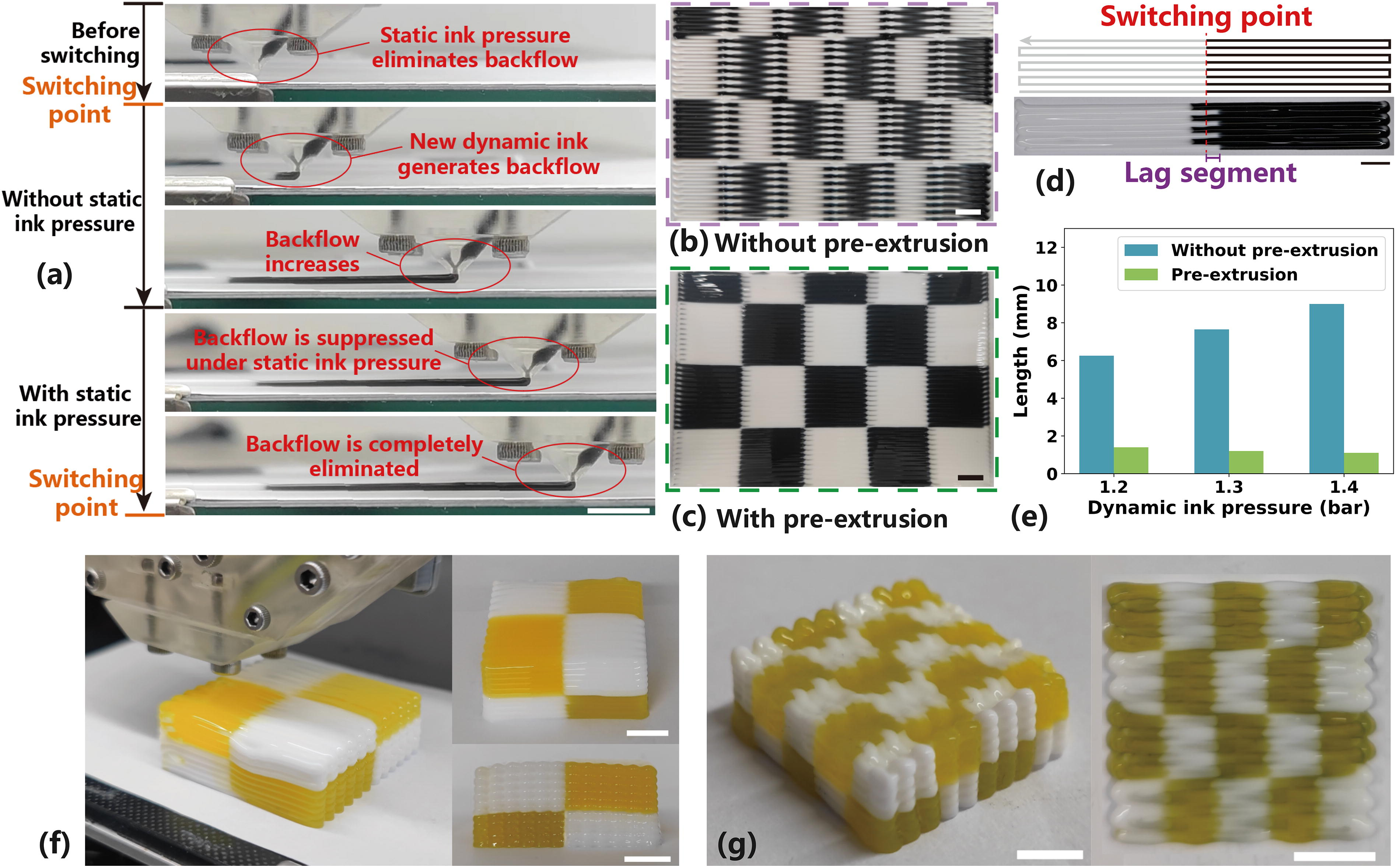
The expression for the dead zone volume Vd is not easy to derive directly. In this study, Vd is estimated by measuring the length of the lag segment. Based on experimental observations, after switching printing materials, the dynamic ink quickly backflows and then stabilizes in a steady state. This process occurs very rapidly, so only the dead zone volume after backflow stabilization is considered. The value of Vd is estimated by measuring the length of the lag segment extruded in the absence of static ink pressure. Figure 4d shows the measurement of the lag segment. As illustrated in Figure 4e, with increasing pressure of the dynamic ink, the length of the lag segment also increases, indicating that the dead zone volume increases accordingly.
Pre-extrusion strategy and printing results (scale bar: 10 mm).
Validation of the pre-extrusion strategy
Figure 4a illustrates the ink switching and extrusion process with pre-extrusion strategy. After the first switch, the dynamic ink will backflow under pressure. Before reaching the second switching point, the static ink (new ink) with pre-extrusion pressure applied will gradually extrude the backflowing dynamic ink (old ink). By the time the switching point is reached, the backflow is mostly eliminated, and only the residual old ink in the Y-junction convergence zone and the end nozzle needs to be extruded to complete the ink switching.
This printing strategy can effectively reduce the lag at switching points while controlling coextrusion. When dealing with periodic patterns that require frequent switching, this strategy can significantly improve printing quality. Figure 4b and c demonstrates the printing results before and after adopting this strategy using a checkerboard pattern. Figure 4b shows the printing result without this strategy; severe lag at the switching points is observed. Figure 4c shows the printing result after adopting this strategy. Although coextrusion occurs near the switching points, clear checkerboard boundaries are visible, and the switching lag is effectively suppressed. Figure 4e compares the lengths of the lag segment with and without the pre-extrusion strategy. It can be observed that the pre-extrusion strategy effectively keeps the lag segment length at a relatively low level (1.1–1.5 mm). As the dynamic ink pressure increases, the lag segment length without the pre-extrusion strategy also increases, whereas the lag segment length with the pre-extrusion strategy remains almost unaffected.
This article prints two cubic samples to further validate the proposed method and the performance of the constructed M-DIW system, as shown in Figure 4f and g. The printing performance of the Rubik’s cube structure demonstrates that the M-DIW system’s multi-material printing not only exhibits low switching lag and high switching sharpness within layers but also maintains good consistency in material switching positions between layers. Additionally, printing multi-material structures that require frequent switching over short distances has always been a significant challenge in the field of 3D printing. However, for the M-DIW system, with its high sharpness and low-lag seamless multi-material switching capability, printing efficiency is not compromised by frequent material switching, and high fidelity can be achieved at switching points, as shown in Figure 4g.
Printing Case Study
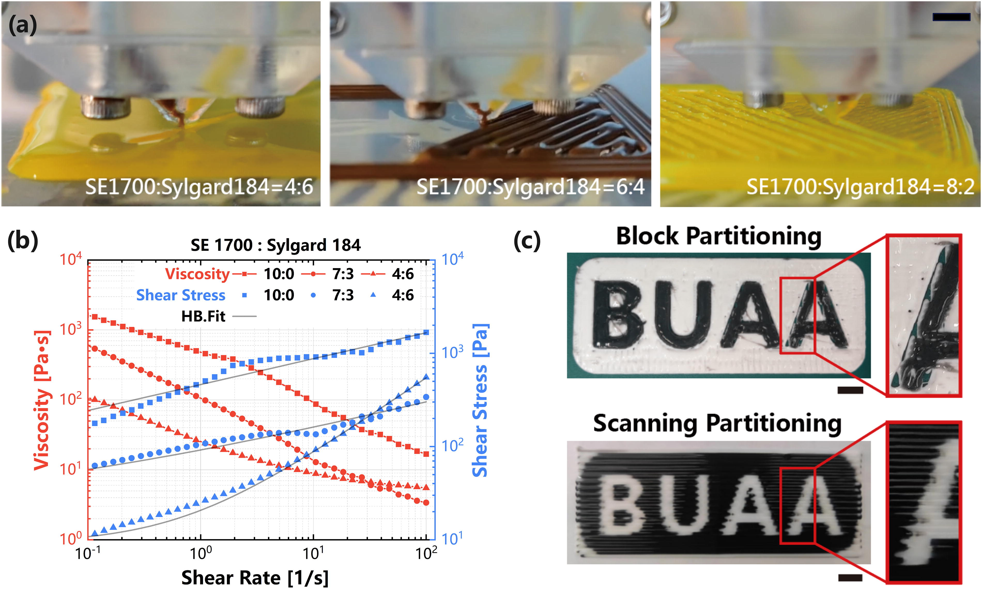
Leveraging the highly flexible multi-material printing capabilities of the M-DIW system, additive manufacturing of soft polymer multi-material structures has become feasible. To enrich the diversity of printing cases, this study investigates different ink formulations and various trajectory partitioning strategies. Figure 5a shows the printing performance of inks with different formulations. The inks used in this study are all mixtures of two silicone gels (SE1700 and Sylgard 184) in varying proportions. The ratio of these two materials affects the properties of the ink. Figure 5b presents the rheological test results of inks with three different mixing ratios. A lower proportion of SE1700 results in a mixture with higher fluidity, which leads to smoother printed surfaces. However, excessively high fluidity is not conducive to printing samples with complex patterns. In addition, a higher proportion of SE1700 results in greater stiffness of the cured samples.
The impact of ink rheology and partitioning strategies on printing outcomes.
Two trajectory planning strategies are considered, including the scanning partitioning strategy and the block partitioning strategy. The scanning partitioning strategy first generates the printing path using the zigzag algorithm and then adds switching points, which significantly increases the number of material transitions. The block partitioning strategy first divides the printing region according to the material type. The printing path fills one continuous region based on the material used before switching to another material and filling the next region. As shown in Figure 5c, the two strategies exhibit different printing performances. The scanning partitioning strategy produces simpler paths and higher material fill rates, but the frequent switching results in jagged material boundaries. The block partitioning strategy avoids frequent material transitions but may lead to insufficient filling between blocks. To better demonstrate the effect of material switching, the previously mentioned chessboard example was printed using the scanning partitioning strategy. In practical printing applications, different path planning approaches should be selected based on the characteristics of the printed part.
In terms of applications, M-DIW technology, with its capability for multi-material integrated forming, offers the potential for manufacturing functional devices with complex spatial distributions of soft materials. As an example, this article demonstrates the fabrication of multi-material samples with deformable capabilities using the M-DIW system, including a flexible hinge (Fig. 6a) and a typical Miura-ori structural unit (Fig. 6b). These two examples were printed using the block partitioning strategy and employed inks with different compositions simultaneously. By editing the materials and their spatial distribution, silicone ink with a lower elastic modulus is deposited in the foldable regions of the structure, while silicone ink with a higher elastic modulus is deposited in regions requiring stiffness. The distribution of inks with varying degrees of softness and hardness defines the bending state of the structure under force, thereby achieving the intended foldable deformation functionality. Compared with traditional deformable structures, these functional multi-material samples can be integrally formed without the need for assembling multiple parts, and the deformation characteristics of the entire structure are highly programmable, making them more suitable for applications in wearable devices, flexible electronics, and other fields. Additionally, this article also demonstrates the fabrication of a semitransparent hydrophobic soft film (Fig. 6c). The film was fabricated using ink with high fluidity and has an ultrathin thickness of ∼250 μm. Circuit traces can be printed on the film, enabling it to serve as a substrate for diverse sensing elements, combining to form waterproof, highly interactive flexible hardware with significant application potential in flexible electronics, soft robotics, and biomedical fields.

Printing case studies (scale bar: 10 mm).
Conclusions
This article designs and constructs an M-DIW system based on pneumatic extrusion control and a multichannel printhead, analyzes the causes of multi-material switching lag and coextrusion issues, and establishes a flow rate–pressure model for ink extrusion. Based on this model, a control strategy for static ink pre-extrusion is proposed, effectively reducing the lag at switching points while controlling coextrusion. The effectiveness of the pre-extrusion method is validated through comparisons of multi-material switching performance. In addition, this article discusses the impact of ink formulation and trajectory planning strategies on the final printing outcomes. Finally, the effectiveness of the developed M-DIW device and the proposed method is demonstrated through a series of printing case studies.
Footnotes
Authors’ Contributions
X.J.: Conceptualization, supervision, and resources. B.S.: Formal analysis, writing—original draft, and visualization. L.Y.: Data curation, methodology, validation, and writing—original draft. J.R.: Methodology. X.D.: Writing—original draft. F.X.: Supervision and project administration.
Author Disclosure Statement
No competing financial interests exist.
Funding Information
This research work is partially supported by “Research Startup funds from Hangzhou International Innovation Institute, Beihang University (2024KQ010)” and “the fundamental Research Funds for the Central Universities (501QYJC2024146013).”
References
Supplementary Material
Please find the following supplemental material available below.
For Open Access articles published under a Creative Commons License, all supplemental material carries the same license as the article it is associated with.
For non-Open Access articles published, all supplemental material carries a non-exclusive license, and permission requests for re-use of supplemental material or any part of supplemental material shall be sent directly to the copyright owner as specified in the copyright notice associated with the article.