




Abstract
Background:
Prostate biopsy false negative percentages are 21% to 47% and 16% to 30% for systematic and fused biopsy, respectively. An intuitive three-dimensional (3D) observed user interface may help reduce these percentages by providing real-time guidance and feedback during transrectal or transperineal biopsy.
Materials and Methods:
We track the moving prostate (including template locations and regions of interest), the transrectal ultrasound (TRUS) probe, and the biopsy device to construct a 3D environment. Users observe, aim, sample, and receive feedback in real time. Using a simulator with simulated TRUS, 48 participants performed freehand systematic prostate biopsy with traditional TRUS guidance and afterward with visualized prostate biopsy (vPBx).
Results:
During simulated biopsy, vPBx reduced the false negative percentage for a 0.5-mL spherical apical lesion from 52% to 2% (p < 0.001).
Conclusions:
Preliminary results during simulated systematic biopsy warrant retrofitting the vPBx to actual TRUS equipment as a step toward clinical trials with patients.
Introduction
The percentage of prostate biopsy false negatives (PBxFN) in systematic prostate biopsy (sPBx; 21%–47%) and targeted prostate biopsy (tPBx; 16%–30%) is not negligible. 1,2 Currently, user interfaces in prostate biopsy systems rely primarily on two-dimensional (2D) transrectal ultrasound (TRUS) images. This may be challenging for users with low spatial ability because it requires mentally reconstructing the complex interactions among the TRUS insonation plane, biopsy device, and prostate to guide the biopsy needle core to the intended biopsy location. Users must be able to interpret cross sections (2D TRUS images) and perform mental rotations. Furthermore, there is no explicit automated feedback in real time regarding sampled cores. It is unknown whether primarily 2D user interfaces and a paucity of feedback contribute to high PBxFN percentages. To explore this possibility, we designed, built, and incorporated a visualized prostate biopsy (vPBx) system into an existing prostate biopsy simulator (unpublished observations: Lampotang S, Lizdas DE, Johnson WT, Mei V, Wakim J, DeStephens A, Moy L, Ahmad A, Stringer T; 2020). The vPBx system provides real-time guidance, aiming, and feedback during sPBx and/or tPBx through the transrectal (side-fire or end-fire) or transperineal route. The vPBx system displays a real-time three-dimensional (3D) observation of
(a) a tracked segmented prostate, sPBx template locations, and region of interest (ROI) for tPBx registered to the moving prostate,
(b) a tracked TRUS probe, and
(c) a tracked biopsy device (needle gun).
The vPBx overlays cognitive aids on a 2D TRUS image and a 3D observation.
This study was approved by the IRB (IRB# 201802108).
Discussion of the Technology
The vPBx system is a retrofit kit that creates an overlay of graphical data on a replicated 2D TRUS image transferred in real time through an high-definition multimedia interface cable from an unmodified TRUS machine (Figs. 1 and 2). A prior MRI scan is not necessary. Removable cleanable clips contain magnetic sensors (NDI Model 800, Waterloo, ON) and attach onto the TRUS probe and biopsy device to track their position in 6 degrees of freedom (6DoF; x, y, z, yaw, pitch, roll; Fig. 1) relative to the prostate with 0.2-mm accuracy. The prostate is tracked in 6DoF by an NDI Model 180 magnetic sensor embedded in a urinary catheter placed before the prostate biopsy procedure (Fig. 1). Preliminary tests in a Thiel cadaver indicate that placing the urinary catheter balloon and partially inflating it with only 1.5 to 3 mL of sterile water (from 10 mL prefilled syringe in kit) in the bladder neck, which is preferred, provides comparable prostate tracking to placement in the prostatic urethra. We developed the vPBx system using the System of Modular Mixed and Augmented Reality Tracking Simulators rapid development platform. 3

A vPBx kit retrofits real-time 3D observation guidance and feedback to unmodified prostate biopsy equipment. 3D = three-dimensional; HDMI = high-definition multimedia interface; TRUS = transrectal ultrasound; vPBx = visualized prostate biopsy.
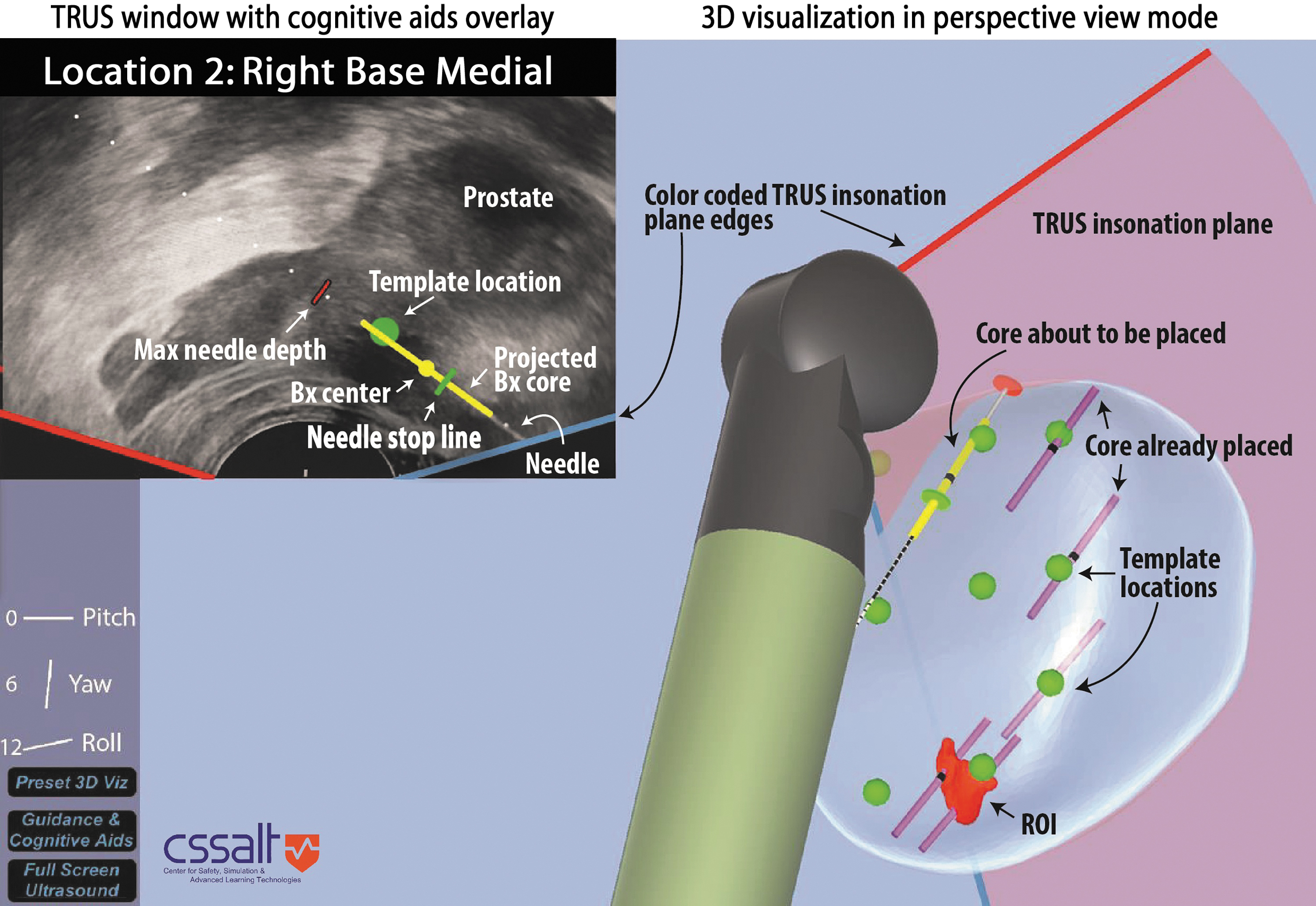
A 2D TRUS overlay and 3D observation guidance and feedback. Targeted prostate biopsy has been completed with two cores placed in the ROI at the right apex. Systematic prostate biopsy after targeted prostate biopsy is in progress. 2D = two-dimensional; ROI = region of interest.
Prostate segmentation in the urology clinic
Toward the start of the procedure, the urologist segments the prostate by manually tracing on the replicated TRUS image contours for different prostate slices. The user moves the dual insonation plane (sagittal, transverse) TRUS probe (e.g., BK 8818) to acquire five sagittal slices (one midline with the urethra visible, two per prostate half) and three transverse slices (one at widest transverse cross section; Fig. 3). The urethra and any lesion visible in the TRUS image are also segmented. This pragmatic segmentation takes about 1 to 2 minutes, resulting in a usable 3D prostate displayed in the vPBx guidance and feedback graphical user interface (Fig. 2). The segmented 3D lesion is rendered visible and targeted in the vPBx 3D mode and 2D TRUS overlay mode. This allows targeted biopsy of ROIs visible in TRUS (53.1% of impalpable cancers 4 ), without the need for an MRI. If the ROI is not visible in TRUS, targeted biopsy cannot be performed without an MRI and the technology is used to ensure that sampling of the prostate is evenly spaced and uniform through the prostate.

Rapid prostate and lesion (if visible) segmentation in the urology clinic.
Features of the vPBx
Several features guide the user. The green circle represents the intended sPBx template location (Fig. 2). The stop line informs the user how far to manually insert the needle tip and turns from gray to green if the deviation is acceptable (≤2 mm). The yellow line moves as the biopsy device is pushed forward and indicates where the core will be sampled if the biopsy device is fired. The yellow circle is the center of the predicted core. The red line indicates the maximum excursion of the biopsy needle tip when it springs forward when fired and is used to avoid unintentionally striking the urethra or bladder. The red line moves as the tracked biopsy device is moved (Fig. 2).
In addition to the TRUS image overlay (Fig. 2, top left), vPBx provides 3D observation guidance and feedback (Fig. 2, bottom right) where the TRUS probe position and orientation relative to a segmented 3D prostate is displayed in real time. The TRUS insonation plane is the pink sheet of light emanating from the TRUS probe tip; a green sphere appears in the 2D TRUS image and in the 3D observation, indicating the template location. The displayed needle path in the 3D observation (side-fire needle guide; Fig. 2) helps users aim the needle toward the template location. The default 3D perspective in Figure 2 is a clinician performing sPBx on a patient in the left lateral decubitus position. Users can set any desired perspective, for example, a patient in the lithotomy position. The three lines on the left display the TRUS probe orientation using aircraft terminology: pitch, yaw, and roll. The pitch line can be used to maintain the TRUS probe horizontally.
The unmodified TRUS image on the TRUS machine remains available at all times (Fig. 1). The TRUS overlay, 3D guidance, and automated feedback are on a separate touch screen (Surface Pro i7; Microsoft Corp., Redmond, WA) that urologists can ignore or turn off. If needed, the retrofit kit can be disabled and removed in about 10 seconds during an ongoing procedure without affecting the unmodified equipment.
sPBx template customization
Users can select various sPBx templates with a different number and pattern of cores that they drag as a 3D set of points into the segmented prostate. If needed, such as in the case of an enlarged prostate, users can manually adjust or add template locations to ensure that there will not be large unsampled regions. Anterior zone (AZ) template locations can be added. This feature is especially important for black patients who have more significant and dominant lesions in the AZ 5,6 and patients with prior negative biopsies. 7,8 Users can adjust the sequence in which the cores in a template are presented for sampling minimize time and motion.
Register third-party segmented prostate and ROI into vPBx
Although the vPBx does not require a prior MRI scan, if a segmented prostate (A) including ROIs is already available from third parties, it can be imported and registered to the 3D prostate (B) segmented by the urologist in the urology clinic. Figure 4 shows manual registration of third-party prostate A to the vPBx segmented prostate B using sagittal and transverse views. At the conclusion of the registration, the third-party ROI is registered in prostate B and can be targeted within vPBx (Fig. 2). This could be of significant interest given the retrofit nature of the vPBx and the potential cost as current systems tend to be expensive.
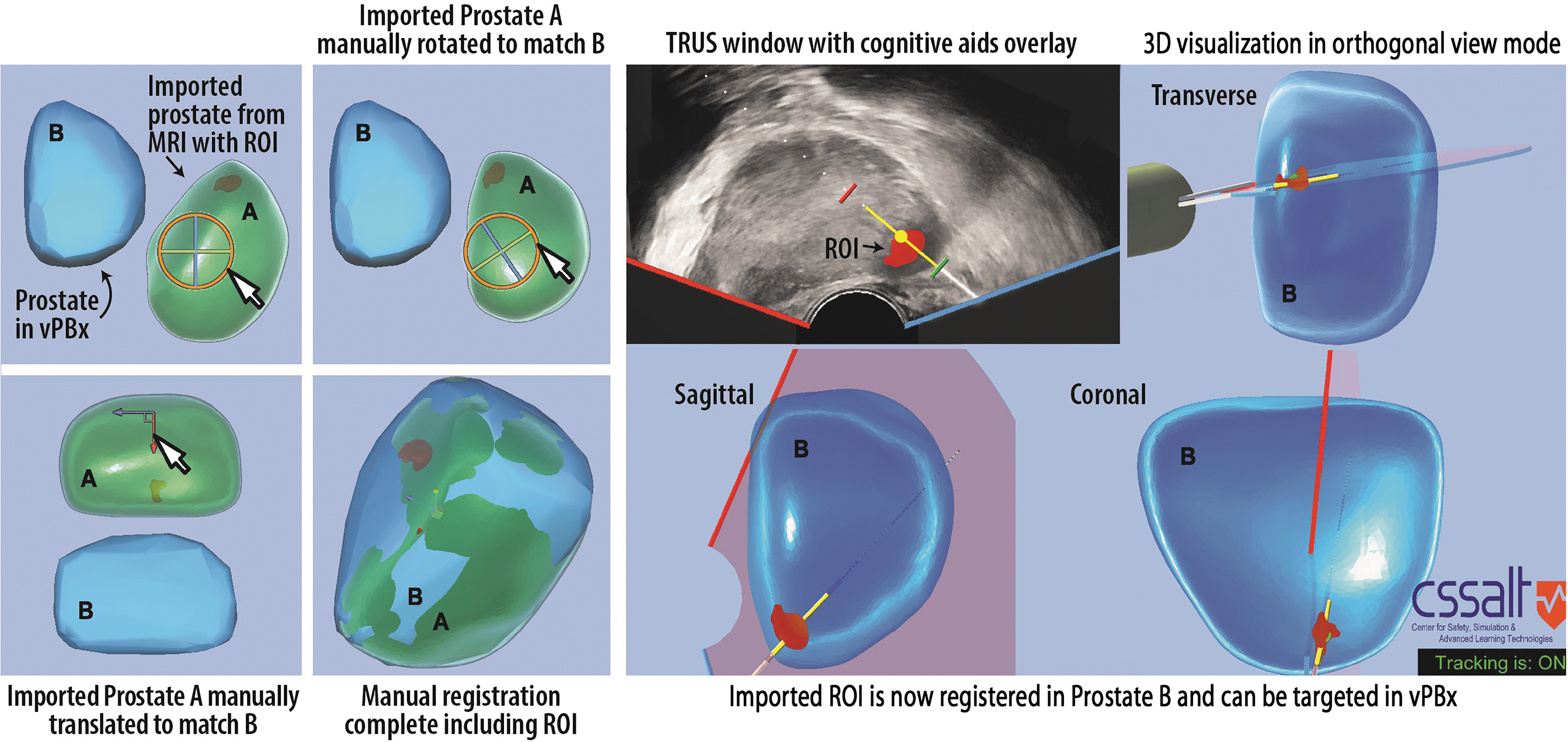
Importing and targeting an ROI from a prior MRI scan into the vPBx system.
Preliminary data
Table 1 presents vPBx performance data during simulated transrectal sPBx only; we have not yet validated targeted techniques and transperineal approaches. Forty-three urology residents and five nonclinicians practiced on a simulator with and without the vPBx. Deviation is the shortest distance between the center of a core and its intended sPBx template location. Template deviation is the average of the deviations for all template locations in a template. There was a significant decrease in mean template deviation (11.8–2.5 mm; paired t-test, p < 0.001) and the percentage of PBxFNs (52%–2%) when using the vPBx compared with traditional TRUS-guided sPBx. We performed a one-sample t-test between PBxFN percentages using traditional TRUS and vPBx. The t-statistic was significant at the 0.05 critical alpha level, t(47) = 6.433, p < 0.0001.
Template Deviations and False Negatives Using Traditional Transrectal Ultrasound vs Visualized Prostate Biopsy
vPBx reduces template (mean) deviation (p < 0.0001) and PBxFN percentage (p < 0.001) for a 0.5-mL apical spherical lesion during 12-core double-sextant sPBx using a simulated TRUS image (n = 48 study participants). Deviation is the shortest distance between a core center and its intended template location. The complete table is available in the Supplementary Video S1.
PBxFN = prostate biopsy false negative; SD = standard deviation; sPBx = systematic prostate biopsy; TRUS = transrectal ultrasound; vPBx = visualized prostate biopsy.
Status
All evaluations of the vPBx to date (Table 1) have been with a simulated TRUS image from a PBx simulator (Supplementary Video S1). The University of Florida has filed a patent application for the vPBx technology.
9
Video can also be seen at
Future directions
We intend to retrofit and integrate the vPBx to actual PBx equipment: BK Flex Focus 400 TRUS machine, BK 8818 TRUS probe, and Bard Max-Core MC1825 biopsy device. Our goal is to evaluate the vPBx integrated with actual PBx equipment with simulated physical prostates, then cadavers, followed by a clinical trial on patients.
Role in Endourology
As an alternative to sPBx and tPBx, vPBx provides 3D observation for aiming and feedback that may reduce PBxFN percentages and sample clinically significant prostate cancer earlier. That would enable diagnosis and treatment to be initiated without delays caused by PBxFN. The vPBx system may facilitate AZ sampling that is not currently performed, although it is recommended for black men suspected of having prostate cancer 5,6 and patients with prior negative biopsies. 5,8
Footnotes
Authors' Contributions
All authors made substantial contributions to the conception/design of the study; the acquisition, analysis, or interpretation of data for the study; and drafting and revising the article. All authors gave final approval of the version to be published and agree to be accountable for all aspects of the study.
Author Disclosure Statement
Lampotang and Lizdas are the inventors on a patent application filed by the University of Florida for the vPBx technology.
Funding Information
This study was supported by the University of Florida (UF) Office of Technology Licensing Commercialization Fund and the UF Department of Anesthesiology (Joachim S. Gravenstein Endowed Professorship to S.L. and D.L.).
Supplementary Material
Supplementary Video S1
Abbreviations Used
References
Supplementary Material
Please find the following supplemental material available below.
For Open Access articles published under a Creative Commons License, all supplemental material carries the same license as the article it is associated with.
For non-Open Access articles published, all supplemental material carries a non-exclusive license, and permission requests for re-use of supplemental material or any part of supplemental material shall be sent directly to the copyright owner as specified in the copyright notice associated with the article.
