
Abstract
Abstract
As we look toward Mars for the next frontier of space exploration and colonization, there is a need to prepare supporting technologies that will allow humans to live on the Red Planet for an extended duration. This article explains the design for a low-mass, autonomously deployable solar array that generates the required power for scientific, habitat, and in situ resource utilization functions necessary for humans to exist on Mars. The Mars Autonomous and Foldable Solar Array (MAFSA) can fit within a 10 m3 stowed volume and deploy to a 1,000 m2 surface with a mass of <1,500 kg. The Triangular Rollable and Collapsible booms, developed by Roccor, are the foundation of the design. Their ability to wrap in a stowed configuration allows for a stowage performance that rivals inflatable architectures and still provides a similar structural performance to that of rigid booms when deployed. While MAFSA is currently intended for Mars use, it can be equally effective on the Moon where inflatable designs are unable to utilize an atmosphere.
Introduction
A successful Martian solar array will be lightweight and compactly stow a large photovoltaic surface into a relatively small volume on the lander. When deployed, the design will then have the structural integrity to overcome the dynamic Martian environment with rough and unpredictable surfaces, dust, and high velocity winds.
Current studies demonstrate significant power requirements for in situ resource utilization (ISRU) and human operations on Mars.1,2 The solar array chosen for these studies is based on the Orbital ATK Ultraflex design, a proven design on the Mars Phoenix Lander but at a relatively small scale. The estimated Ultraflex system mass of 1,040 kg corresponds to a total solar surface of 176 m2. However, with the current efficiency of photovoltaics, a total photovoltaic surface area of 1,000 m2 is necessary to meet the ISRU power requirements and match the power production capability of nuclear fission systems for Mars. 3 As a result, the Ultraflex design and similar designs that utilize rigid booms will have a significantly large mass budget for a Mars mission with the current power requirements. On the opposite end of the design space, inflatable technologies have been considered since early in planetary exploration efforts.4,5 Inflatable technologies are attractive due to their light weight and high packaging efficiency. However, inflatable architectures are unpredictable in deployment, require continuous pressurization, and run the risk of punctures. Inflatables also face challenges at destinations that do not have an atmosphere such as the Moon. Given the benefits and drawbacks of these general design architectures, a balance between the two has the potential to decrease the risk of a Mars mission while also reducing the system mass and volume, and with that reducing the overall mission cost.
MASFA must adhere to the following operational requirements for the mission to be considered successful:
MAFSA (Mars Autonomous and Foldable Solar Array) shall operate for a minimum of 10 years on the Martian surface. MAFSA shall be resilient against dust particles on the micron scale. MAFSA shall be capable of surviving long-duration Martian storms with wind speeds up to 50 m/s. MAFSA shall produce power at end of life sufficient to support human activity on Mars. MAFSA shall be serviceable by human crews on the Martian surface.
MAFSA was designed with three major considerations in mind:
The stowed volume must be no >10 m
3
. The mass must not exceed 1,500 kg. The total photovoltaic charging area must be a minimum of 1,000 m2.
Considerations 1 and 2 are predicted by NASA to be constraints imposed by launch vehicles available by 2030. Consideration 3 is derived from requirement 4 given predictions of human habitation power levels and current photovoltaic technology.
It is important to keep in mind that MAFSA has the potential to be scaled up to a limited extent or down to a much greater extent depending on the application. MAFSA as described here is approaching an upper bound on boom technologies available to support such a large photovoltaic area, such that scaling-up becomes difficult. In contrast, since MAFSA is plausible at the proposed size, scaling the entire assembly down can be achieved to some minimum hub diameter to support internal electronics, gears, and bearings.
The MAFSA module is a cylinder with a radius of 2.5 m and height of 0.5 m to meet the stowed volume constraint. The design uses five flexible booms that are stowed in a wrapped configuration around a central hub. The stowed height of the booms is 20 cm, allowing for an additional 30 cm of height used for stowing the folded solar array around an upper hub. During deployment, two electric motors rotate the hubs, forcing the booms to extend out of the lander and the solar array to unfold into a pentagon pattern. The array can also retract with the ability to resume its original stowed configuration for dust and storm mitigation.
In the deployed state, the area of the array is slightly >1,000 m2, with 21 m booms extending to the corners of the pentagon. Each fifth of the pentagon array is designed with 80 radial fold lines that allow for a stowed height of 30 cm. Dust mitigation is accomplished by partially retracting the booms and allowing dust to fall through holes placed in the troughs of the array. During partial retraction, the array transitions from a flattened surface to a zigzag along the fold lines, allowing for 80 sections in each module to be angled toward the ground. Figure 1 provides a simplified representation of MAFSA in the deployed state. The following sections address the technologies and their integration, which comprise the foundation of the MAFSA array design as well as the operational plan for the array on a dynamic Martian surface.
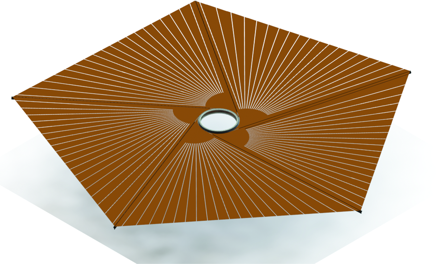
Fully deployed MAFSA array. MAFSA, Mars Autonomous and Foldable Solar Array. Color images available online at www.liebertpub.com/space
Existing Technologies
Deployable Boom
The flexible booms used in this design are a scaled-up version of Triangular Rollable and Collapsible (TRAC) booms originally invented by the Air Force Research Laboratory and developed by Roccor. When stowed, the booms take on a flattened shape minimizing stowage volume and allowing them to wrap 360. When deployed, the booms unfurl at one end to allow for maximum axial and vertical strength. Up to this point, TRAC booms have only been used in CubeSat applications where the maximum boom length was 4 m. 6 The booms are made from a unidirectional Hexcel® IM7/977-2 carbon fiber composite.
Retraction and Deployment Motor
Two 3-phase, 4-pole induction electric motors are used for rotational deployment and retraction of the booms. An example of this motor can be found in a Tesla Roadster and can produce up to 185 kW of power output with a maximum torque of 270 Nm.
Bearings
Rotation of MAFSA's central hub requires large bearings (4 m outside diameter). Kaydon Bearings are a potential manufacturer for these unique bearings. The Kaydon NG series bearings are a lightweight ball bearing designed for radial loads. Kaydon manufactures these bearings up to a 1-m outside diameter. To meet the specifications of MAFSA, the bearings need to be scaled to an outside diameter of 4 m. The estimated mass of the scaled bearing is ∼54 kg. The estimated thickness of the bearing is 5 cm. The bearing can operate up to an ∼300 kN radial load and up to a 750 kN thrust load. 7
Photovoltaics
XTJ Prime triple junction thin film solar cells from Spectrolab are a potential option for the solar array. These cells are more promising over solar cells from Alta Devices, SolAero, and Azure Space for their low relative mass and comparable efficiency. Spectrolab solar cells come in a 3.97 cm-by-6.91 cm rectangular cell size. The area mass density is 500 g/m2. These cells have a beginning of life efficiency of 30.7% and an end-of-life efficiency of 26.7%. The thickness of the cells ranges from 60 to 225 μm. 8
Solar Cell Substrate
DuPont Kapton PV9100 Series polymide film can be used as the solar cell substrate. The material has been successfully implemented in space PV applications, and provides protection to the thin film cells. It has a thickness of 50 μm. 9
Design Overview
MAFSA can be broken down into three primary components: the central hub, the booms, and the solar array. Each component will be discussed individually, followed by a description of the mechanical relation between each component. Finally, a short description of the lander design for MAFSA will be provided. The quantitative specifications hereafter are designed to meet the 1,000 m2 photovoltaic surface area constraint for one unit. However, as mentioned previously, the MAFSA concept can be scaled down, and multiple units can be used to meet a power production requirement. With that said, the general design, integration of components, and operational plans are the most important results of the following sections.
Central Hub
The hub, as shown in Figure 2, is composed of two stacked central aluminum cylinders (labeled 2 and 5) with a fixed metal plate (5) separating both cylinders, and a fixed base metal plate upon which MAFSA is constructed (10). A central shaft (10), 3.9 m in diameter, runs from the base plate to the top of the module. Above the base plate is the 20 cm tall, 4.9 m diameter cylinder (5) used for boom stowage. The base plate and mid plate are joined by sixteen, 20 cm tall, aluminum supports (9) that are positioned at the outer perimeter of the plates. The upper cylinder (2) is 30 cm tall and 4 m in diameter for array stowage. Each cylinder is mounted onto the fixed central shaft using a bearing system (1) that allows for rotational motion. The two sections are constructed, so that the lower section provides boom compactness, as discussed below, and the upper section allows the array to deploy without obstruction.
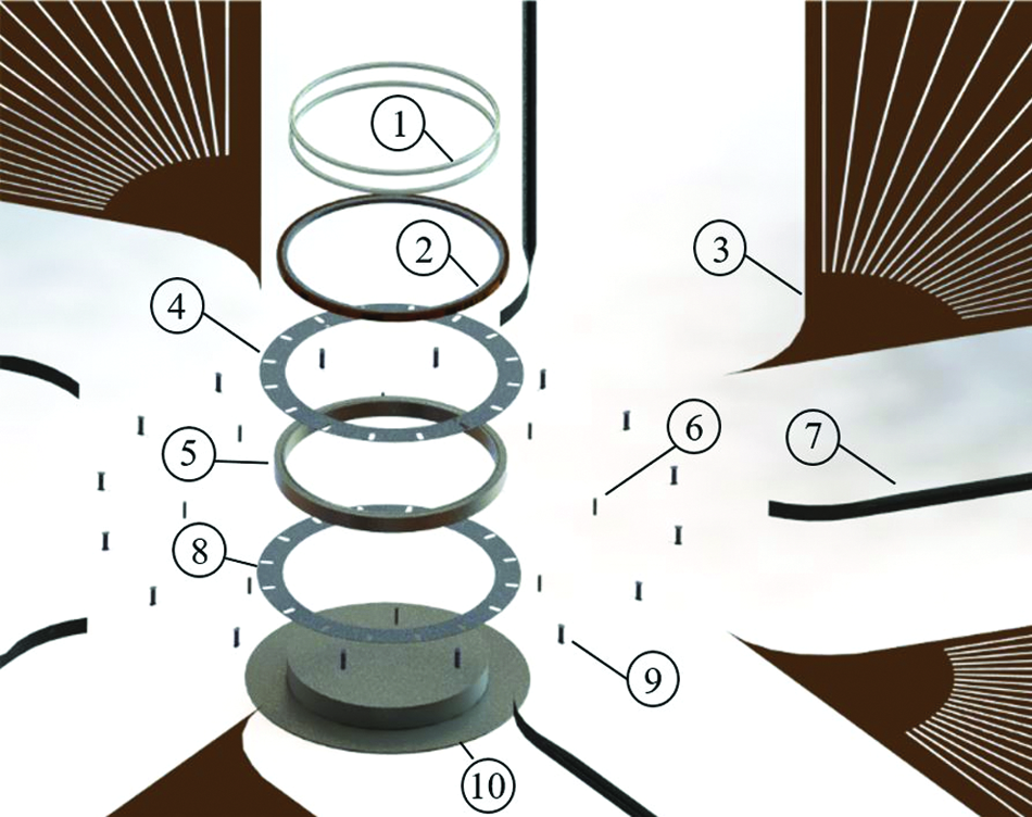
Exploded view of hub and array. See Central Hub section for explanation of components. Color images available online at www.liebertpub.com/space
In addition to the supports attaching the upper and lower plates, 16 spring-fixed rollers, as shown in Figure 3, are lined along the outside of the lower cylinder section. These rollers guide boom wrapping as tightly as possible, preventing severe buckling in the boom.

Rollers allowing booms to transition from stowed to deployed state. Color images available online at www.liebertpub.com/space
To assist with deployment, there are five additional guiding rollers located at the points where booms are transitioning from a stowed state to a deployed state. These rollers set boundary conditions as the booms unfurl at their open ends and assist in a straight-line deployment tangent to the hub. In addition, a brush can be placed outside of the guiding rollers to sweep dust from inside the booms upon retraction.
Batteries and power electronics are stowed inside of the lower aluminum cylinder. These components lie on the lower plate of the hub, while being protected from outside influences by the enclosure created by the cylinder.
Bearings
To allow for rotation of the cylinders around the central shaft, two slim ball bearings are placed between each cylinder's inner face and the shaft. These bearings must be lightweight and have very large diameters relative to their height. Kaydon manufactures bearings up to an outside diameter of 1 m, which meet all the technical requirements of the MAFSA mission. A bearing with an outside diameter of 4 m has a predicted mass of 53.7 ± 0.5 kg.
These bearings are subject to, over a 10-year mission, ∼220 full rotations or 110 h of operation. Typical bearings like these are rated for thousands of hours of continuous operation under full loads, making the MAFSA use requirement well below their capabilities.
Gears
Rotation of the lower and upper cylinder is powered by two 250 Nm electric motors stowed inside the hollowed-out lower cylinder. The deployment and retraction of the solar array are possible with a single motor, but a second motor reduces the strain on a single motor and adds redundancy for a crucial mechanical component. A single gear mechanically connects the motor shaft and a gear lining along the inner cylinder wall, as shown in Figure 4. A second gear lining is placed along the top of the lower cylinder that is used to relay the rotational motion to the upper cylinder. As seen in Figure 4, a small hole is cut out of the fixed middle plate, so that two gears, fixed to the central shaft, can reach down to the lower cylinder lining and relay rotation to the upper cylinder gear lining. The gear ratio between the upper and lower cylinders is 1.225 to allow for the array and boom to wrap at equivalent rates.
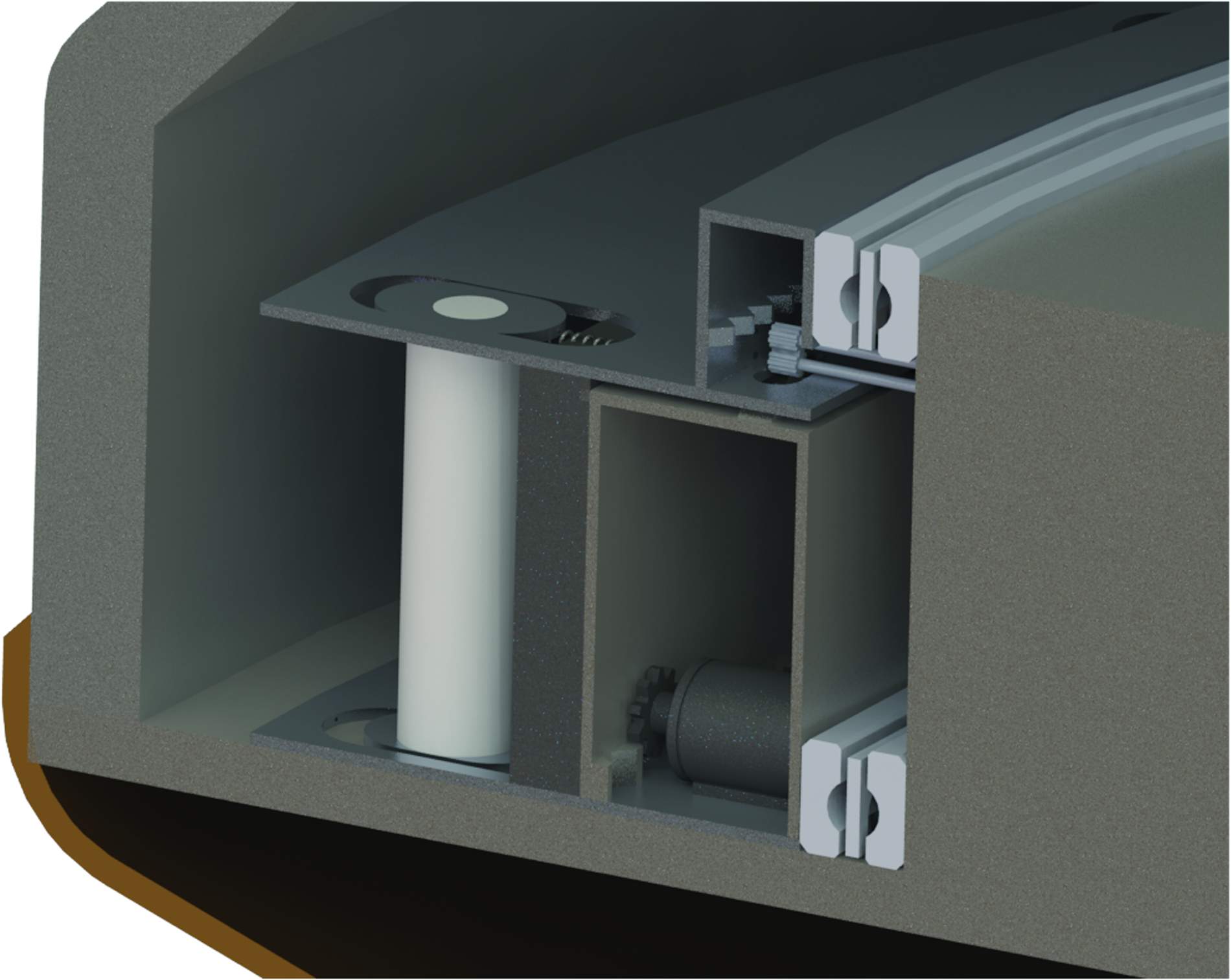
Rotational gear system showing lower and upper cylinder with fixed separating plate. The central shaft has been excluded for visual purposes. Color images available online at www.liebertpub.com/space
Booms
A single TRAC boom is 23 m long, including stowed and deployed length, and made from a Hexcel IM7/977-2 carbon fiber composite with a mass density of 1,780 kg/m3. The total mass of the five booms is 626 kg. A boom takes on two different shapes for stowage and deployment.
In the stowed state, both flanges are compressed together to minimize bending stiffness about the y-axis. This allows the booms to be wrapped around a 360° curvature if the radius of curvature is larger than a minimum bound set to prevent fiber failure during stowage. 10 In the deployed configuration, as shown in Figure 5, both flanges are opened to an angle, θ, which allows for a higher bending stiffness about both the x- and y-axis. Using equations developed by Roccor for these boom geometries,10,11 MATLABs fmincon optimization function was used to find max stiffness given mass, stowed height, strain while wrapped, and twist constraints. Bending stiffness about the x- and y-axis is characterized by Equations (1) and (2):
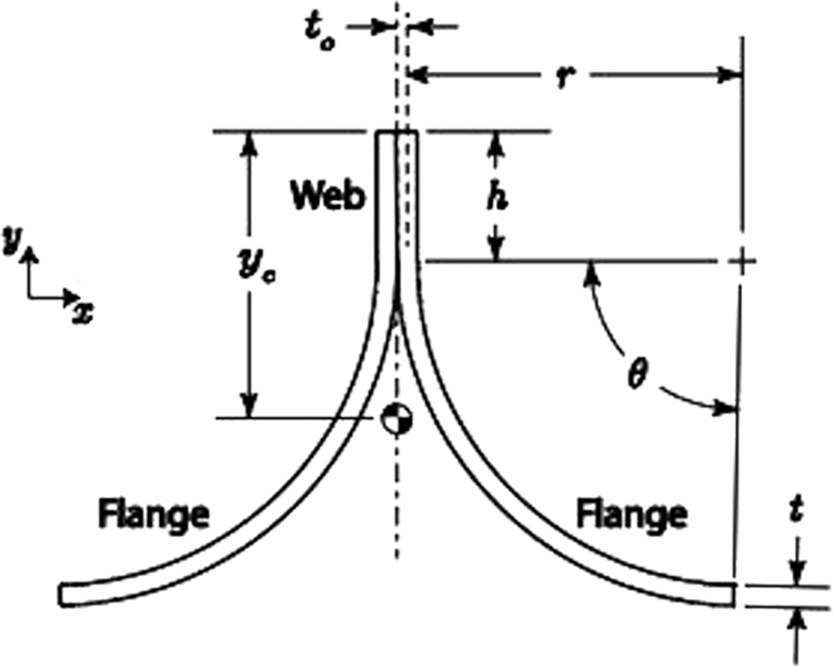
Head-on view of TRAC boom. TRAC, Triangular Rollable and Collapsible. 11
where the dimensions and axis are summarized in Figure 5. The mass was limited to a max of 630 kg, and the stowed height was constrained to a max of 35 cm by the volume requirements for the system. The maximum tolerable strain while wrapped was 1.5%, given by the ultimate elongation at failure for IM7 carbon fiber of 1.9%. Strain was estimated using Equation (3):
where Δκ is the radius of curvature in the x or y direction, and t is the thickness of the boom. Maximum twist due to torque on the boom from the array was set to 10°. Twist of the boom was determined using Equation (4):
where T is the torque from array loading see Deployed State section, G is the modulus of rigidity set to 5 GPa, and J is the torsional constant for the boom. J is defined in Equation (5):
where θ, r, h, and t are defined in Figure 5. The result of the optimization routine was boom dimensions of h = 14 mm, r = 28 cm, θ = 0.63, and t = 8.0 mm.
The relationship between two of the four boom dimensions and the bending stiffness is illustrated in Figures 6 and 7. It is important to note that the equations given above are assuming the orientation shown in Figure 5. Orienting the booms with the free end of the flanges facing upward, where they would be in tension when supporting the solar array, increases the bending stiffness about the x-axis by three times compared with a face-down orientation. 10 MAFSA utilizes the flange upward approach, opposite to the orientation shown in Figure 5.

Moment versus boom thickness, t0. Color images available online at www.liebertpub.com/space
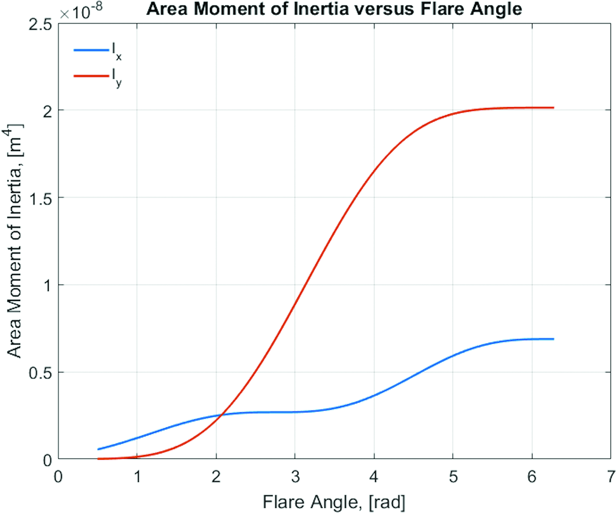
Moment versus flange angle, θ. Color images available online at www.liebertpub.com/space
Booms are long enough to be wrapped around the circumference of the lower cylinder within the lander module 1.5 times. When fully deployed, each boom has 2 m of remaining length attached around the cylinder using bolts and braces drilled through the boom and the metal cylinder.
Solar Array
The solar array is a single unit that forms a pentagon of 1,060 m2 when deployed with a 20 m2 circular lander in the center. A triangular fifth of the array has 80 evenly spaced segments extending radially from the hub to the end of the triangle. There are two types of guiding lines that form a segment: one is simply an indented path along the array substrate, and the other is formed by a pattern of connection points and openings along a guiding path. The latter allows for open spaces in the array used for dust removal.
The outer edge of the array is attached to a carbon fiber grating that provides tension along the edge, and supports uniform folding and unfolding. The spaced guiding lines are attached to the troughs of the grating, as shown in Figure 8.
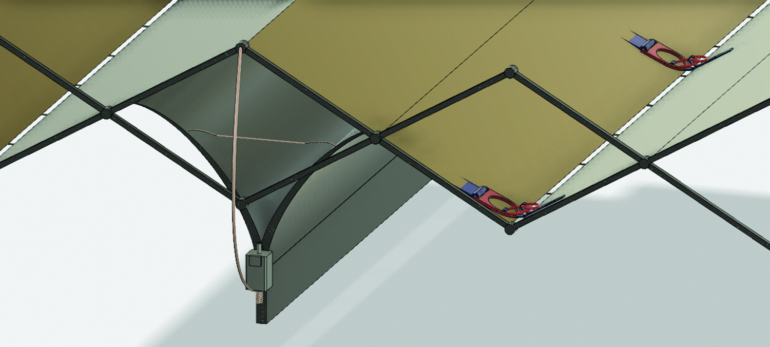
Array grating and attachment to boom. Color images available online at www.liebertpub.com/space
The array rests on top of the booms with the corners of the pentagon attached to the boom ends. A second attachment point connects the array to the central hub. The point of contact at the hub is secured using bolts through holes in Kapton that have been reinforced with metal rings. Solar array folds allow the array to be stowed in a zigzagging manner while wrapping about the upper cylinder. Each array corner is attached to the boom ends using a steel cable that wraps around a small stepper motor fixed to the boom, as shown in Figure 8. The stepper motor has a thin power cable running through the boom back to the lower cylinder where a controller is connected. When stowed, the motor allows the connecting cable to become slack, allowing compartmentalization of the array and booms. As the booms deploy, the motor begins winding the cable taut to gradually pull the array tight to the booms.
Each segment of the array contains 928 solar cells. A segment is divided into 20 series strings of 46 cells each to provide 130 V at end-of-life, accounting for the cell's temperature coefficient. Each string provides a current of 0.18 A at the maximum power point, meaning that 20 strings tied in parallel generates 3.6 A. A 14 gauge wire forms the 130 V bus that each string is tied to. This wire runs through a plastic sheath into the upper cylinder to prevent dust from entering the hub. A 0000 gauge wire, or larger, then collects the current from each fifth and send the current to a rotating slip ring that would ultimately lead to stationary batteries. The total mass of these wires is estimated to be 30 kg.
To allow for access to the lander while the array is deployed (and to meet operational requirement 5), a series of three-ring separation mechanisms are used at a pre-existing juncture point along each diagonal of the pentagon array. This three-ring mechanism is used by skydivers to provide a strong connection of their parachute to the rest of the system, and allows for easy separation by pulling a plastic cutoff cord. An example of a three-ring system can be seen in Figure 9.
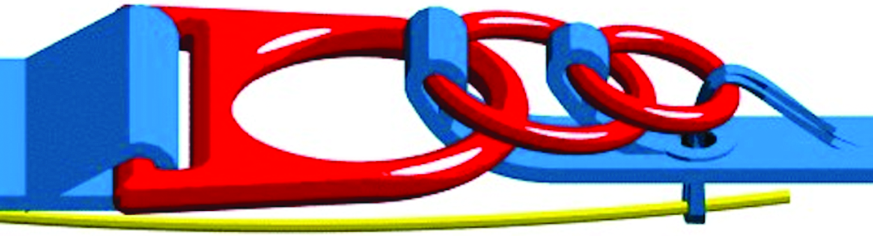
Three-ring system on a skydiving rig. 18 Color images available online at www.liebertpub.com/space
If access to the lander is needed while MAFSA is deployed, one can pull the plastic cutoff cord releasing the first set of rings and continue this process along the length of the array until the lander is reached. To reattach the array, the astronauts couple the rings back together and reinsert the cutoff cords. This is a simple and proven separation mechanism used millions of times by skydivers.
Lander Integration
At this stage in the design, MAFSA does not require a particular geometry or configuration of the lander. The MAFSA module is cylindrical, but because it integrates with the lander through a central shaft, the shape of the lander above and/or below does not need to match the MAFSA module. Other than the central shaft, the components in the module are not directly connected nor provide support to the lander.
The MAFSA module can be positioned at various vertical levels within the lander. The minimum height above the Martian surface is constrained by the max deflection of the booms to prevent dragging or hitting large obstacles during deployment and retraction. From Figure 11, the max downward deflection is 25 cm. To prevent hitting obstacles >50 cm, the minimum height of the module from the Martian surface should be 75 cm. The module can then be positioned within the lander at any height above this minimum.
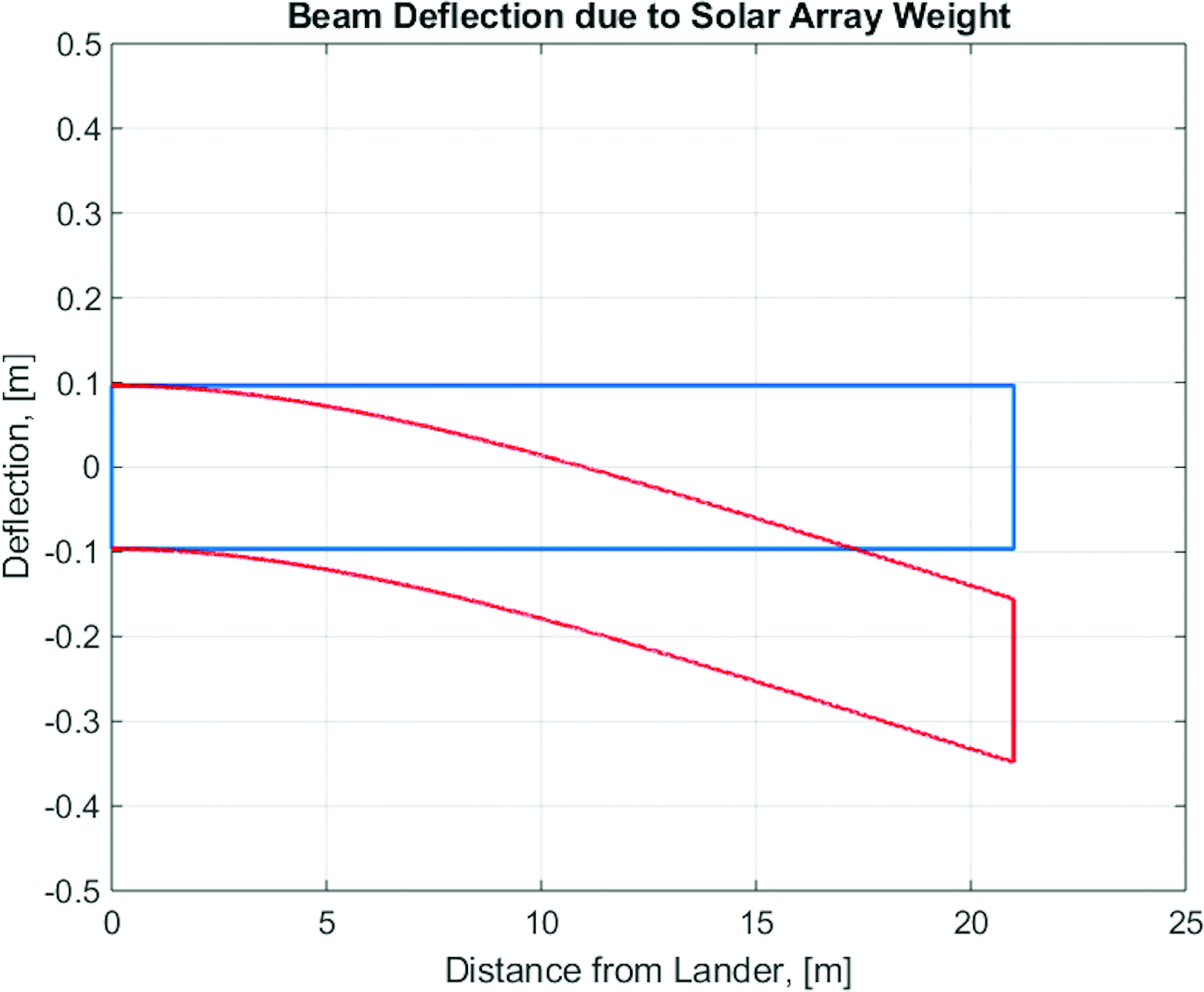
Boom deflection under weight of solar array. The blue rectangle represents the boom without loading and the red rectangle represents the boom with loading. Color images available online at www.liebertpub.com/space
Upon landing on the Martian surface, the sides of the landing module eject and expose the MAFSA module. The general integration of MAFSA within a generic lander heat shield is shown in Figure 10.
MAFSA shown as a modular stowage load in a conceptual Martian lander capsule. Color images available online at www.liebertpub.com/space
Mission Plan
Module Assembly
The MAFSA module can be assembled starting from the center and building radially outward. The central shaft is the core of the module and connects the module to the lander. Bearings are then placed between the central shaft and the rotating cylinders for the booms and the array. The hollowed rotating cylinders are next, with the motors and gears within. The booms and array are attached to the outside of the cylinders. Finally, the guiding rollers and supports are placed around the booms between the base plate and mid plate. A cross-section of the MAFSA module is shown in Figure 4.
Deployment and Retraction
Deployment of MAFSAs booms and array is estimated to take ∼30 min. Assuming that the motor being used is operating at a maximum torque of 270 Nm over the course of constant rotational speed, the total amount of energy required by the motor for deployment is 0.69 kWh. Retraction is accomplished by simply reversing the motor direction.
Initial designs called for supporting legs at the end of each boom. After further analysis, it was determined that only support at the central hub in the deployed state is necessary. Figure 11 shows deflection of the booms, and confirms that legs are not required for support outside of the central hub. Eliminating supporting legs greatly reduces frictional forces while deploying and retracting, minimizing the risk of buckling due to axial forces and permitting predictable mechanical behavior. The problems that large obstacles pose to full deployment are also mitigated by eliminating legs.
Forces that could adversely affect smooth deployment and retraction still exist; most notably, friction between the boom and the lower plate of the hub and pressure from the brush sweeping dust during retraction. The former is reduced by placing rollers under the booms on the base plate. The rollers reduce the maximum torque needed to deploy the booms to <10 Nm, assuming friction-less bearings, while the motors can each produce a torque up to 270 Nm. If the rollers fail, the peak coefficient of friction between aluminum and carbon fiber is 0.6812, giving a max torque of 285 Nm, which can still be overcome with both motors if necessary. Dust in the booms is minimized through periodic partial and full retractions, which prevent significant dust accumulation in the booms. The rate of dust accumulation in the booms is low (on the order of 1 × 10⁵ kg/sol, see Dust Accumulation section), and as a result the additional force exerted to sweep dust is overcome by the motor.
After the initial deployment, subsequent retractions and deployments are driven by dust and storm mitigation, discussed in detail in the Power Generation and Dust Removal and Mitigation sections. It is important to also reduce the amount of retractions per year to increase the lifetime of the mechanical components and to mitigate the risks associated with retraction. MAFSA may partially retract an average of 14–20 times per year for dust removal, with full retractions occurring, on average, once or twice a year during severe dust storms. These estimates are based on dust settling rates and dust storm frequency measured from the NASA Viking and Pathfinder missions.12,13 The operating time for the mechanical components because of retraction and deployment is ∼11 h per year. This operating time is minimal for the parts chosen so long as dust is prevented from entering the bearings, gears, and motor area.
Deployed State
In the deployed state, the array rests on top of the five booms, connected only to the boom ends and the central hub. Two simulations were performed to investigate the loading on the booms from the array in the deployed state. The results confirm that the booms could support the array to a first-order approximation.
The first simulation quantified the downward deflection along the length of the boom. Based on the results from Roccor, the moment of inertia for the v-up orientation used here is three times greater than the moment of inertia for the orientation given in Figure 5. The array was modeled as a uniformly distributed load for simplification. This is a reasonable approximation due to the small angles off the horizontal (∼5°) in the deployed state and the constant density throughout the array. Figure 11 shows the result of the simulation. A max deflection of 25 cm occurred at the end of the boom. The bending stress of the boom was 67 MPa, well under the estimated max flexural strength of 1,800 MPa for an IM7 carbon fiber composite. Based on this result, it was decided that legs to support the booms at the perimeter would not be necessary, but it remains an option as higher fidelity analysis is performed to better quantify the booms' structural performance.
Finite element method (FEM) was used to quantify the moments along the boom due to nonsymmetric loading. Torque is crucial to quantify because the booms have a low torsional stiffness, and enough torsion will cause the booms to fail. In the simulation, the array was assumed to be flat and connected to the boom outer edge along the boom length. The results of the FEM are shown in Figure 12. The maximum reaction torque along the boom is ∼6 Nm for the pentagon case. Figure 13 shows the boom's twist angle because of the reaction torque using Equation (4) and assuming the maximum twist angle to be 10°. We anticpate the boom will withstand a max torsion of 10°. However, further characterizaton of the booms and expected moments are neccessary given the MAFSA dimensions.

Torque on boom from FEM analysis. FEM, finite element method. Color images available online at www.liebertpub.com/space
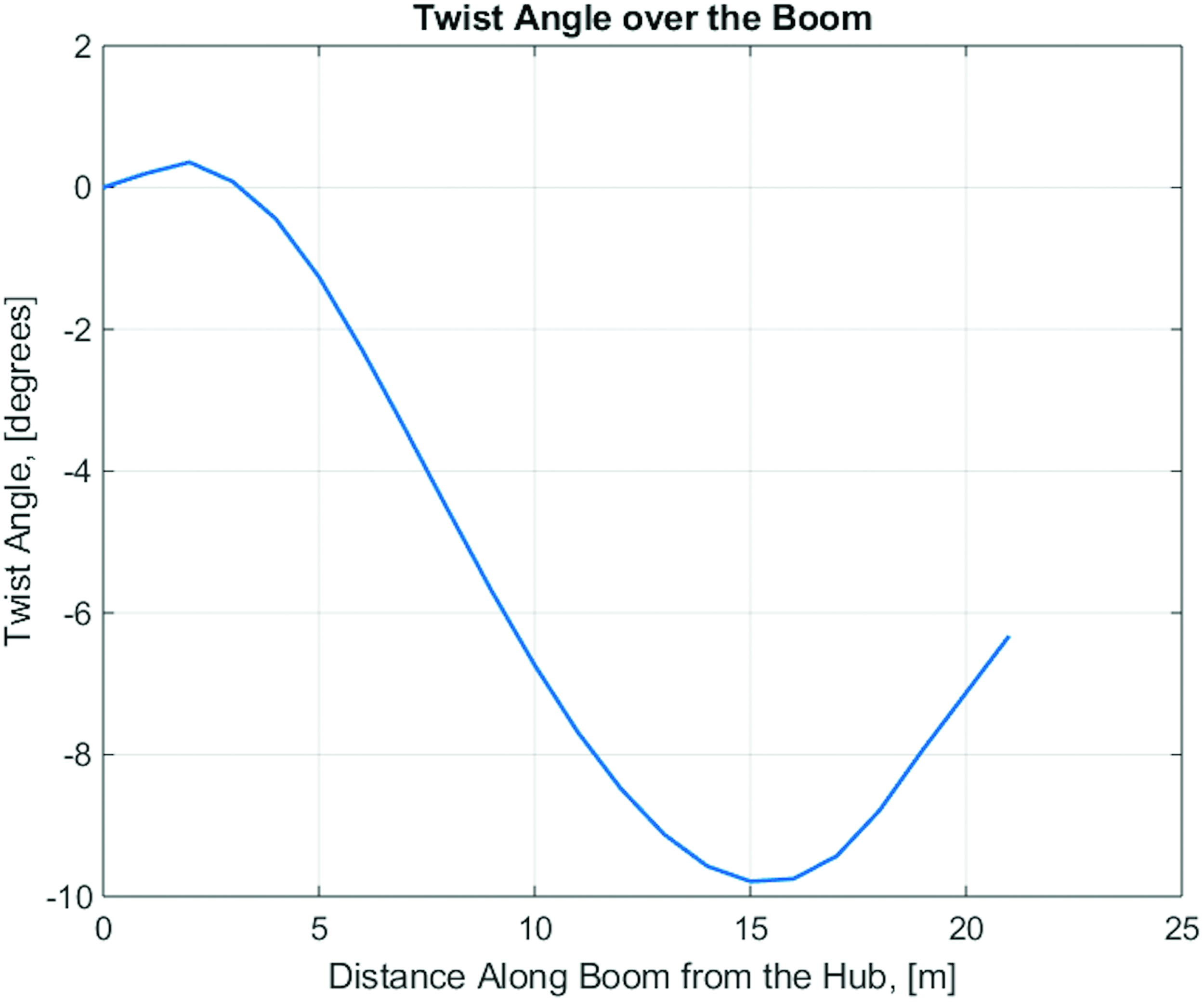
Torsion along the length of the boom. Color images available online at www.liebertpub.com/space
Operation
There are three primary requirements considered in the design for successful operation on a highly variable Martian surface environment. The requirements are power generation, dust removal, and storm mitigation.
Dust accumulation
The rate of dust settling on the array is important to quantify to ensure the array structure does not overload the booms and to maximize efficiency of power generation. It has been estimated using gravitational settling with Stoke's Law that dust settles on the Martian surface at a rate of 30,000 particles/cm2/sol on average. 14 This rate can increase to 240,000 particles/cm2/sol during storms and decrease to as low as 1,200 particles/cm2/sol. To estimate the mass increase associated with these settling rates, one needs to know the size and density of the dust. The geometric mean radius of dust particles is estimated to be 1.85 ± 0.3 μm from analysis of Viking Lander images. 12 Finally, bulk density of the dust is estimated to be 1,520 kg/m 3 obtained from analysis of Pathfinder data. 15 Using these estimates and sampling from a normal distribution of particle sizes, the mean rate of mass increase on the array is 0.01 kg/sol with a worst case scenario of 0.1 kg/sol during storms. These rates indicate that mass overloading of the booms is not a significant concern and removing mass will not be the primary driver for retraction of the array.
In contrast to mass loading, dust accumulation on the arrays does have a significant impact on power generation efficiency. Analysis of Pathfinder data found a daily efficiency loss (obscuration) of 0.28%. 13 A max obscuration of 5% is a reasonable balance to keep power generation efficiency high and to reduce mechanical operations over the lifetime of the mission. At an accumulative obscuration of 5%, MAFSA will implement dust removal operations. Given this threshold and the daily obscuration rate, the estimated amount of removal operations is 14–20 per year.
Power generation
MAFSA at the current size can generate 10–25 kW of equivalent continuous power over a Martian year at the equator. This was calculated using an annual global irradiance profile on Mars, the solar cell efficiency at end of life, an estimated 75% power conversion loss efficiency, modeling of dust coverage and mitigation, and an ideal daily irradiance profile. Power generation estimates considered the array to be flat. This is a reasonable approximation because the array is between 5° and 10° from the horizontal. An angle of 5°–10° corresponds to a minimal decrease in efficiency (98%–99%) compared with a flat array case when the sun is directly overhead. At lower sun angles, the power production matches the flat case over the course of a sol due to symmetry in the array shape and folding.
The daily power output shown in Figure 14 is for a dustless 9-h day at maximum annual irradiance. Due to the expanse of the array compared with the lander profile, the lander shadow does not produce significant variation in the daily power generation of the solar array. An annual daily continuous power output, as shown in Figure 15, was developed using the average power output over a single day as the continuous power equivalent, and assuming that cleaning events every 21 sols restore the array to 98% efficiency. There is a total energy loss over the course of a Martian year of only 5% from the case without dust obscuration. Figure 15 also shows estimated power requirements for the ISRU phase and human-deployment phase. A single MAFSA unit cannot meet the power requirements for these phases, and thus multiple units are needed to meet operation requirement 4. This is an anticipated result for a solar array with a surface area of 1,000 m2 operating on the Martian surface.

Daily power output with ideal solar profile accounting for lander shadow. Color images available online at www.liebertpub.com/space
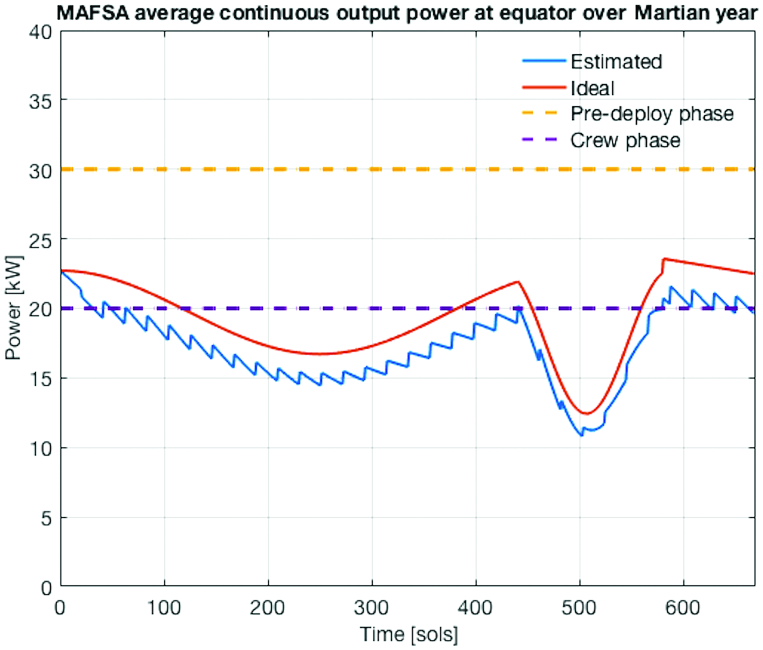
Annual equivalent continuous power output with dust storm event shown at ∼450 sols. Color images available online at www.liebertpub.com/space
Dust removal and mitigation
Dust and debris removal is a necessary consideration for a solar array to operate efficiently and autonomously on the surface of Mars. The folded design of MAFSA provides a straightforward mechanism to prevent dust buildup on the photovoltaic surface. In the stowed state, the angle between folds is effectively 0°, while in the fully deployed state the angle between folds is ∼170°. Thus, even in the deployed state, the panel is never perfectly flat, and is instead a series of peaks and troughs. As dust settles into the troughs, it falls through slits in the substrate and back to the ground. However, a 170° angle between each fold in the deployed state means that each fold is 5° from horizontal. The angle needed to overcome the frictional force can be found by the simple relationship μf = tan(θ), where μf is the coefficient of friction between the dust and photovoltaic material and θ is the angle of the solar array fold from the horizontal. Most dry materials have a coefficient of friction between 0.3 and 0.6, which means that the array fold must have an angle between 17° and 31° from the horizontal.
The van der Waals adhesion force is more difficult to quantify but is significant at the micrometer dust particle size scales. 16 The adhesion force can be overcome with the same method used to overcome frictional forces. However, this requires a steeper angle of 45° from the horizontal found from laboratory experiments with Mars dust simulants. 17 Retraction to 45° happens at night, and allows time for dust to fall or be blown off by natural winds. The array would retract by 11 m to reach the desired angle, consuming 0.3 Wh, a relatively low-energy cost.
In summary, dust removal from the array is accomplished by retracting the array to an angle of 45° at night and then returning to the fully deployed state before sunrise. This mechanism provides a simple but effective dust mitigation strategy with low-energy costs, which fits naturally with the structural design of the array. It does not need to rely on mechanical vibration or forms of an electromagnetic dust shield, which add significant complexity and are unproven for structures of this size.
Dust can also accumulate in the inner volume of the booms. The rate of accumulation is minimal, but over time or after severe dust storms the dust inside the boom could produce significant loading. A V-shaped brush positioned just outside the central hub sweeps dust out of the array during retraction. Inevitably, dust will pass the brush and begin to accumulate at the interior of the brush during redeployment. There are small holes near the web of the boom just inside the brush at full extension. Once the system begins to extend, the brush serves as a second barrier, and any remaining dust caught on the hub side falls into the holes back to the Martian surface after redeployment.
Finally, dust mitigation within the central hub is crucial for successful operation over the array's lifetime and to meet requirement 2 in the introduction. The central hub is designed so the only parts exposed to the Martian environment are the booms, the array, and the outer cylinder, which the booms and array wrap around. The motor, bearings, and gears are all within the outer cylinder (Fig. 4) protected from the Martian environment. Plastic trim and rubber rings can be used at the base of the upper and lower cylinders to prevent dust from entering the gaps between the fixed and rotating components.
Storm mitigation
Dust storms on Mars can last for months and produce winds up to 50 m/s. While the atmosphere has a density of only 0.02 kg/m 3 at the surface (∼60 × less than Earth's atmospheric surface density), storms could still have detrimental effects, given the area of the deployed array, its low mass, and the size of the supporting booms. In the case of intense storm events, the array can be retracted and stowed as described in the Deployment and Retracton section. However, the array cannot be in a stowed state for every storm event because power is needed continuously for human and ISRU operations.
A series of simulations were performed to understand the effects of a storm on the deployed array. To simplify the aerodynamic analysis, it was assumed that the boom could be modeled as a flat plate perpendicular to the flow. Under this assumption, the coefficient of drag is 1.2819. The deflection was calculated assuming a uniform load given by the drag per unit length. Figure 16 shows the deflection in the boom due to aerodynamic forces in a 50 m/s flow. The boom is being viewed from above, the lander is to the left, and the uniform flow is coming from the bottom of the plot. The max bending stress on the boom for 50 m/s wind is 119 MPa, which is well under the estimated max flexural strength of 1,800 MPa for an IM7 carbon fiber composite.
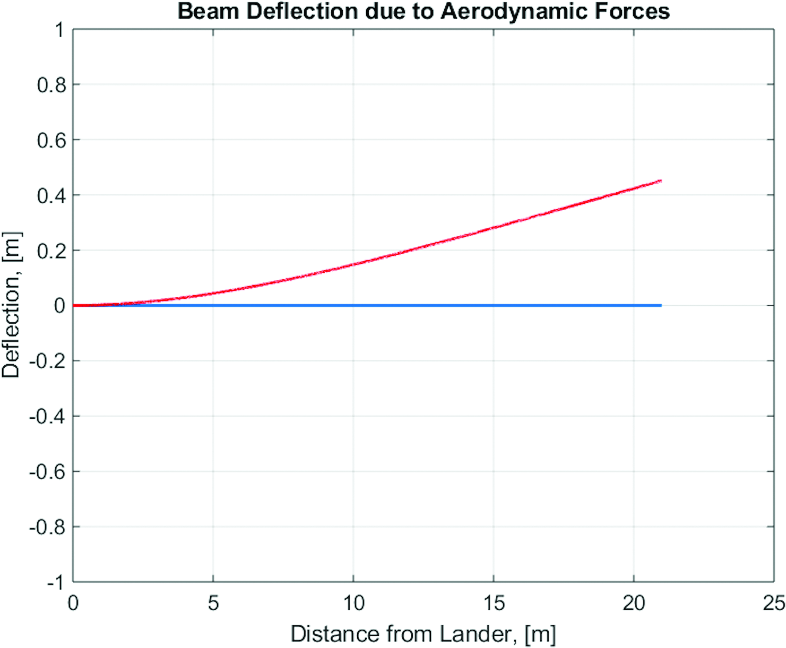
Boom deflection with 50 m/s winds. The blue line represents the boom with no winds and the red line represents the boom with 50 m/s winds. Color images available online at www.liebertpub.com/space
The size of MAFSA's flexible surface area raises an additional concern from the aeroelastic effects of storms. However, due to the complex interaction between the structure and the turbulent aerodynamics around MAFSA, a detailed, formal analysis is beyond the scope of this work. Steps have been taken to mitigate the risk of failure. Specifically, the flexible solar array's movement is constrained on the outer boundary, air can escape from underneath through the holes that are also used for dust mitigation, and the array is retracted during storms with high winds. For these reasons, MAFSA to a first-order approximation meets requirement 3 stated in the introduction.
Conclusion
The MAFSA is a solution for the power production demands to support human activity on Mars. MAFSA is a low-mass, mechanically simple design, with the structural stability to withstand the dynamic Martian surface. The design expands upon technologies that are currently in development, most notably, the Roccor TRAC booms, but also includes novel ideas (i.e., solar array stowage and deployment folding and dust mitigation strategies) necessary to meet the large solar surface area requirements and power performance. The folded nature of the array substrate is a crucial aspect of the design that provides structural rigidity in the deployed state, allows for guided, predictable deployment and retraction, and provides a natural dust mitigation mechanism. MAFSA is a self-contained unit that can be scaled and integrated on a variety of lander platforms, and produces the large total photovoltaic surface area necessary to support humans on Mars.
Footnotes
Acknowledgments
We first thank Kamron Medina from Roccor for his help in determining TRAC boom characteristics through shared papers, tours of their facility, and availability for technical questions. We also thank Professor Francisco Jimenez for sharing his knowledge on deployable space structures and mechanical analysis.
Author Disclosure Statement
No competing financial interests exist.