




Abstract
Rocket takeoff and landings result in high structural loads on the launch surface and the rocket components along with elevated noise levels. This article presents an experimental study of a jet issued from an axisymmetric Mach 4 converging-diverging nozzle operating at highly over-expanded conditions and impinging on a flat surface, representing rocket takeoff and landing conditions. Shadowgraph technique was used to visualize the flowfield to gain insight into the qualitative behavior of the jet. Mean and unsteady pressure measurements on the impinging surface were carried out to study the associated flow physics. Nearfield acoustic measurements were conducted to understand the relationship between the fluid flow and the acoustic field. Microjet-based flow control was employed to suppress flow unsteadiness and reduce noise levels. The results show that both pressure loading on the impingement surface and nearfield noise are strongly dependent on the nozzle pressure ratio. The pressure and acoustic spectra measured at various locations are broadband without any discrete tones. The use of microjets results in a fuller and more stable jet at the nozzle exit and shows a dramatic reduction in the unsteady loads on the impingement surface and overall sound pressure levels.
Introduction
The advent of advanced reusable rockets and boosters plays a crucial role in making space exploration cheaper and viable. With the development of reusable technology, new challenges arise, such as ground erosion, structural fatigue, and noise pollution. Some of these issues are associated with the rocket propulsion system designed to operate over a broad range of conditions. Here, propellants are ignited to produce high-temperature and pressure gases that exhaust at supersonic speeds from the nozzle, as seen in Figure 1. Today's converging-diverging (C-D) rocket nozzles employ the same principles as was first suggested by Goddard 1 100 years ago. Flow through the C-D rocket nozzle begins subsonic in the converging section of the nozzle and accelerates to the sonic velocity at the throat. The flow further expands to supersonic speeds in the diverging section. During most of the flight time, the nozzles operate at off-design conditions. At lower altitudes, the nozzles operate at over-expanded conditions, whereas at higher altitudes, the nozzles are under-expanded. Over-expansion of nozzle flow leads to unsteady and cross-stream loading due to flow separation and unsteady flow features inside the nozzle. These complex phenomena create hurdles in making rockets safe and efficient. Further, during liftoff and landing, when the nozzle is near the ground, the rocket exhaust impinges on the ground and produces a highly oscillatory and unsteady flowfield along with very high noise levels. Such a flowfield is detrimental to the near and farfield structures, the safety of launch vehicles, and a severe health hazard to the personnel in the vicinity of launch pads.
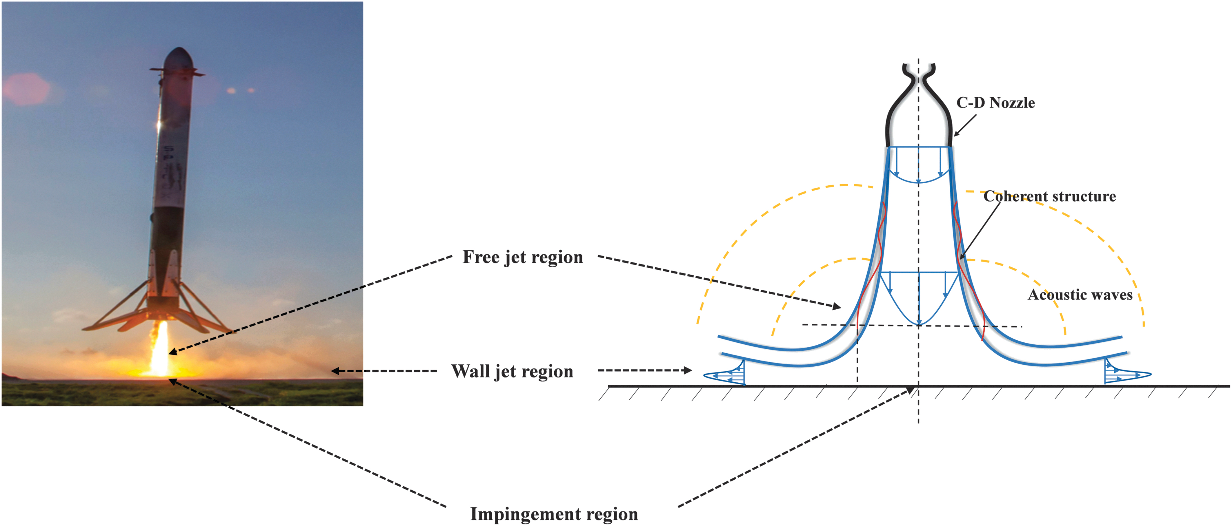
Left: SpaceX booster landing (Credits: www.spacex.com), Right: Schematic of an impinging jet flowfield. Color images are available online.
Acoustic emission during a launch operation results from complex interactions between distinct phenomena such as impingement of jets on the ground, flow through the launch table opening, and the interaction of multiple jets. 2 Various methods to suppress this noise are implemented at the launch sites, such as the use of inclined surfaces that deflect the flow and the use of water and deflector ducts. These noise suppression techniques exist only at the rocket liftoff and not the landing sites, which are usually separate. Since controlling the noise output and unsteadiness is crucial, devising a suppression technique independent of the launch or landing site becomes essential. The current study examines the effectiveness of an active flow control technique in altering the flowfield, noise levels, and unsteadiness, under conditions including liftoff or landing configuration.
It is crucial to characterize the flow inside the diverging section of over-expanded C-D nozzles. Under this regime, it is well known that nozzles exhibit shocks inside the diverging section. Although some of the literature, such as Hunter, 3 Papamoschou and Johnson, 4 and Ostlund and Muhammad-Klingmann, 5 indicated the persistence of flow separation and plume unsteadiness, they also observed asymmetry in the flowfield. Hunter 3 proposed that flow separation resulted in asymmetric flow. On the other hand, shocks in the diverging section were found to influence the flow's symmetry, as demonstrated by Papamoschou and Johnson 4 and Ostlund and Muhammad-Klingmann. 5 Ostlund and Muhammad-Klingmann 5 suggested that a transition between two different shock patterns, namely free shock separation and restricted shock separation, leads to transverse loads on the nozzle. More recently, Khobragade et al. 6 studied the flow associated with an over-expanded rocket nozzle by using the particle image velocimetry (PIV) technique and static pressure ports inside the nozzle and noticed a decrease in nozzle efficiency due to flow separation. Although these studies are limited to free jet plumes discharged from rocket nozzles, understanding the flowfield and noise characteristics due to over-expanded jet impingement, a review of fundamental studies relevant to jet impingement on a ground surface, is warranted.
Many researchers have studied jet impingement in applications such as impingement cooling in turbines, electronic equipment cooling, and short takeoff and vertical landing (STOVL) aircraft, with STOVL being the most relevant to the rocket plume jet impingement. Donaldson and Snedeker 7 extensively studied jet impingement and suggested that the flowfield can be divided into three regions, namely the free jet regime where the flow is devoid of any interaction with the impingement plate, the impingement regime where the jet interacts with the impingement surface leading to a change in the direction of the flow, and the wall jet regime that consists of the radial flow along the surface. Under certain operating conditions, studies suggest that the flow develops extremely high unsteadiness levels and large-amplitude acoustic fluctuations in high-subsonic (Wagner, 8 Nosseir and Ho 9 ) and supersonic impinging jets (Krothapalli et al., 10 Worden et al. 11 ). The resulting process is often described in terms of a feedback mechanism in literature12–14 constituting three processes. First, vortical structures in the jet shear layer are formed due to Kelvin-Helmholtz instability that convects downstream as they increase in size and impinge upon the ground plane. This leads to high-pressure fluctuations on the ground plane and the production of acoustic waves, which then propagate upstream. Finally, these waves disturb the shear layer at the nozzle lip and initiate the new instabilities, thereby closing the loop.
Wagner 8 reported the presence of audible tones for jet Mach numbers greater than 0.7 issued from a convergent nozzle and reported that the frequency of tones decreased by increasing the nozzle to plate distance up to a limit and then jumped to a higher frequency, which he described as staging. These high-amplitude fluctuations are known as impinging tones. Nosseir and Ho 9 studied the subsonic impinging jet by correlating the nearfield and farfield microphone with surface pressure measurements. Their study concluded that both the free jet instabilities near the nozzle exit and the impingement of large structures on the ground plane contribute to the noise. The study also suggested that the large-scale coherent structures travel at a velocity of 0.6 times the velocity of the jet, producing strong acoustic waves after impingement on the plate.
Researchers employed several techniques in the past for the reduction of noise and minimizing the unsteadiness in free and impinging jets. One of the techniques involving microjets has been proven to be efficient in noise reduction and decreasing lift loss. Alvi et al. 14 employed the use of microjets in an attempt to disrupt the feedback loop mechanism. The microjets located at the periphery of the nozzle exit caused a dramatic reduction in lift loss, unsteady pressure loads, and nearfield noise. Kumar et al. 15 studied impinging jets on a Mach 1.5 ideally expanded high-temperature jet on a flat plate to understand the flowfield and noise generation for STOVL applications. The study utilized the shadowgraph technique for qualitative measurements and PIV for quantitative data collection. The results show that using a microjet control reduces nearfield noise, unsteady pressures, and thermal loads. Microjets reduce the pressure fluctuations on the ground plane and lift plates by up to 20 and 15 dB, respectively, as well as nearfield acoustic levels up to 8 dB. More recently, in the study of free jets, Khobragade et al. 6 found that suitably positioning an array of microjets in the diverging section of an over-expanded rocket nozzle delayed the onset of flow separation and improved the jet stability.
The main objective of the present study is to characterize the aeroacoustic properties of impinging jet flow discharged from an over-expanded rocket nozzle, with the jet impinging normal to the ground plane. Pressure (mean and unsteady) and acoustic measurements were made on the ground plane and in the nearfield, respectively. Qualitative flow visualizations were also performed by using a conventional shadowgraph technique to understand the global flow features. Flow control using high momentum microjets was employed to enhance the performance and reduce the flow unsteadiness of the jet plume.
Experimental Setup and Test Conditions
Test Facility
Experiments were performed at the STOVL facility of the Florida Center for Advanced Aero-Propulsion (FCAAP), located at Florida State University. The compressed air source was a set of tanks with a capacity of 110 m3 that supply air at a maximum of 3,450 kPa. The nozzle was attached to the stagnation chamber, and the pressure and temperature of the jet were controlled by a high-pressure valve to achieve the desired nozzle pressure ratio (NPR). A series of honeycomb straighteners and meshes are installed upstream of the nozzle and downstream of the stagnation chamber to condition and streamline the flow. The nozzle to ground plane distance was varied by using a traverse mechanism connected with a stepper motor to simulate the change in the distance of the rocket exhaust plane from the ground during vertical liftoff/landing. A circular impingement plate insert of diameter 266.7 mm was mounted on a large rectangular ground plane to study the impinging jet flow.
Figure 2 shows the schematic of the test setup and measurement locations. The tests were performed by using an axisymmetric C-D stainless-steel rocket nozzle of design Mach number 4, shown in Figure 3. This corresponded to an expansion ratio of 10.72 and a design NPR of 151.4. The converging part of the nozzle was designed by using the fifth-order polynomial and the diverging section based on the Method of Characteristics. The nozzle has a throat diameter (dt) of 12.7 mm and an exit diameter (de) of 41.65 mm. More detailed drawings of the nozzle and facility can be found in Vemula et al. 16
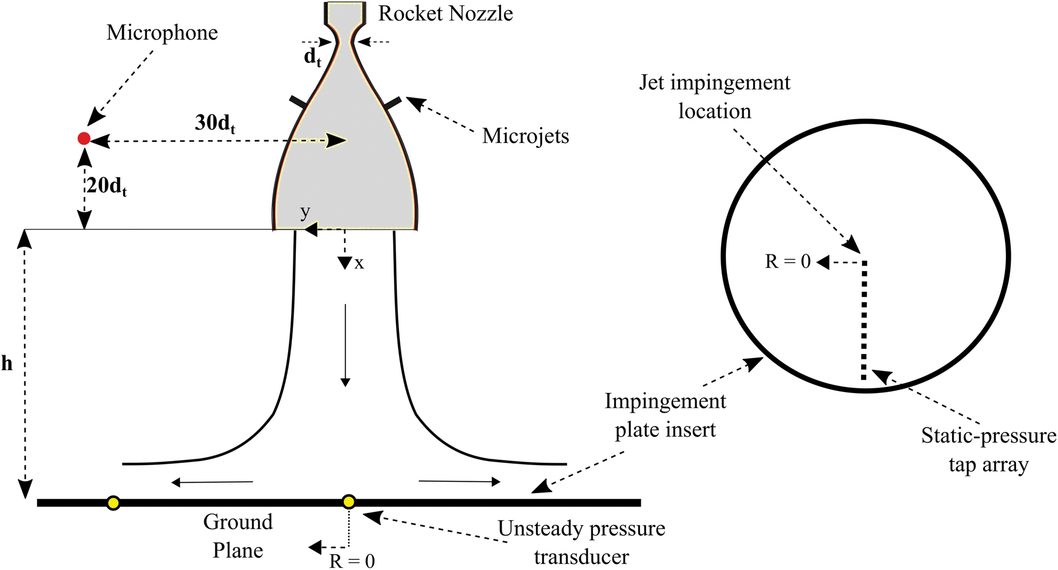
A schematic of the experimental setup, including locations of the microphone, unsteady pressure transducers, and static pressure ports on the ground plane. Color images are available online.
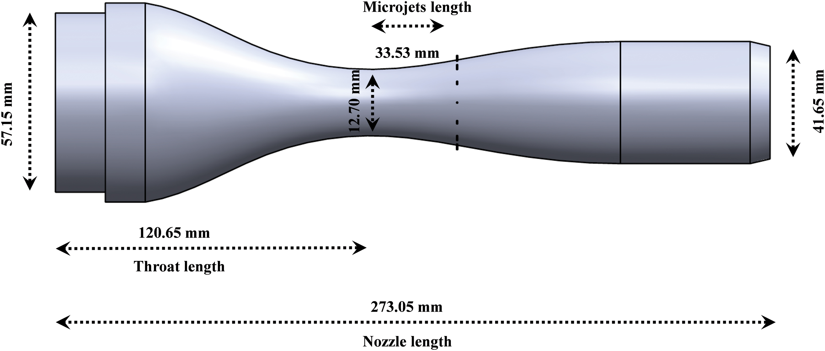
A schematic of the rocket nozzle with dimensions. Color images are available online.
Test Conditions
The current study was carried out at NPR = 4, 5, and 6 to simulate highly over-expanded conditions. All experiments were conducted at isothermal conditions of a temperature ratio (TR) of 1.0. The ground plane to nozzle distance (h) was varied from 2dt to 12dt. Fourteen equally spaced 0.4 mm diameter microjets were placed azimuthally in the nozzle, at an axial distance of 2.64dt from the throat, to implement active flow control. This optimal location for microjets was chosen based on previous studies by Khobragade et al. 6 The microjets supplied air at a pressure of 344 kPa through stainless steel tubing at an injection angle of 90° to the nozzle outer surface. Table 1 summarizes measurement techniques and test conditions.
Measurement Techniques and Test Conditions
NPR, nozzle pressure ratio; TR, temperature ratio.
Measurement Techniques and Instrumentation
Shadowgraph flow visualization
The flow was visualized by using a conventional Z-type single-pass shadowgraph method. Figure 4 presents a schematic of the shadowgraph setup. The setup consists of two 0.3 m diameter parabolic concave mirrors of focal length 2.54 m each and f-number = 8, placed on either side of the nozzle. A light-emitting diode (LED) was utilized as a pulsed white light source and was focused through a series of lenses onto a slit. The beam then traveled to a concave mirror through a folding mirror (the folding mirror was used due to confined laboratory space), and the resulting collimated beam was passed through the flow region of interest. The parallel beam then traveled to an identical second concave mirror on the other side of the test section and was captured by using a high-speed Photron FASTCAM SA5 camera after getting reflected by a second planar folding mirror. In the present study, the images were captured at a resolution of 1,024 × 1,024 pixels, a frame rate of 60 Hz, and the exposure was kept at 2.5 μs to visualize the instantaneous flow features.
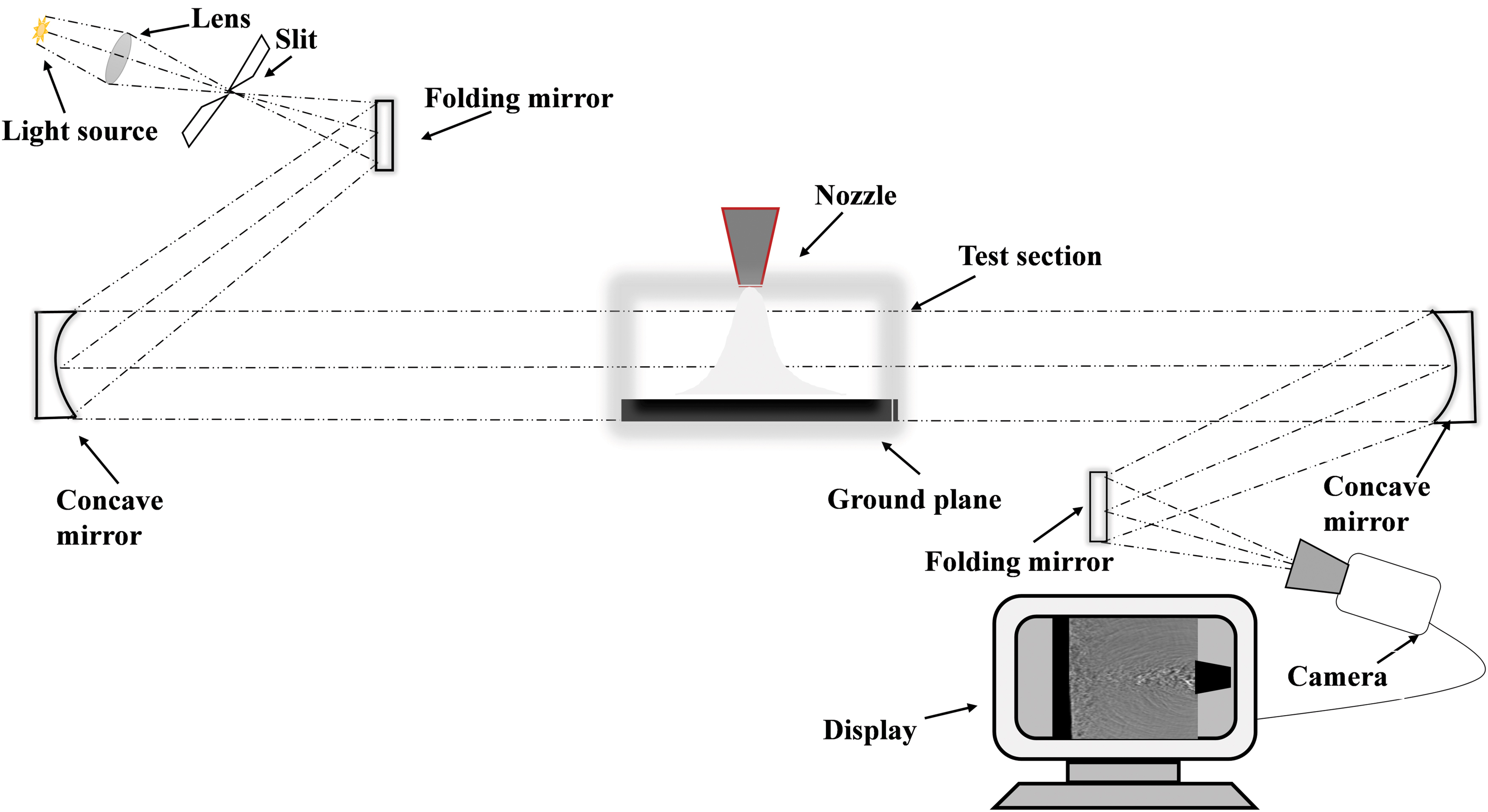
A schematic of the z-type shadowgraph setup. Color images are available online.
Pressure measurements
The mean pressure distribution was measured on the ground plate by using 16 pressure taps arranged as a radial array (Fig. 2), which were connected to a 16-channel, 206.82 kPa differential ESP scanner. In addition, the flow-induced pressure fluctuations on the impingement plate were measured with two high-frequency 1.6 mm diameter Kulite pressure transducers (model no. XCE-062-100A) placed at R/dt = 0 and 4.25 on the impingement plate (Fig. 2). The pressure transducers were carefully calibrated by using a Druck DPI 610 pressure calibrator before the tests. The measurements involving the static pressure scanner and the unsteady pressure transducers were carried out in two separate test campaigns.
Nearfield acoustics
In addition to pressure measurements, nearfield acoustic measurements were performed by using Brüel & Kjaer 4939 ¼ inch (6.35 mm) diameter microphone. The microphone was placed at an axial distance (y) of 30dt from the nozzle axis and an axial location (x) of 20dt upstream of the nozzle exit plane, pointing directly toward the nozzle. This position was chosen to prevent the wall jets from directly influencing the microphone measurements. A B&K 2960 C signal conditioning amplifier was used to amplify the signals. The signals were further processed through low-pass analog filters (Stanford systems SR-650) at a cut-off frequency of 50 kHz. The microphone was calibrated before the tests by using a B&K 4228 type pistonphone at a frequency of 250 Hz and an amplitude of 124 dB. Nearby metal surfaces of the test facility were covered with acoustic foam to minimize sound reflections, as the tests were conducted in a nonanechoic environment. The sampling of microphone data was synchronized with that of unsteady pressure sensors.
Pressure and acoustics signals were acquired through National Instruments data acquisition cards and were monitored by using LabView software. The microphone and Kulite transducers were sampled at a rate of 102.4 kHz for 4 s at each test point. A frequency resolution of 25 Hz was achieved by averaging a total of 100 FFTs of 4,096 samples each, and the results were postprocessed by using the MATLAB computing platform. The ESP scanner has a full-scale precision of ±0.15%, with uncertainty in pressure measurements of ±0.4 kPa. The NPR values are accurate within ±0.0375. The measurement uncertainty in the unsteady pressure signals provided by the manufacturer is ±0.5% of full-scale output, which translates to ±0.12 kPa.
Results and Discussion
To study the aeroacoustic characteristics of the impinging jet, a Mach 4, C-D nozzle operating at highly over-expanded conditions is experimentally investigated at different NPRs and nozzle standoff distances. As indicated in the test matrix, the data were collected at several operating conditions. Typical results are presented in the following sections to demonstrate the global flow features.
Impinging Jet Flow Features
The conventional shadowgraph technique was utilized to visualize the nozzle exhaust flowfield. Instantaneous shadowgraph images at h/dt = 6 for the baseline flow (without control) and with control at various NPR are presented. Figure 5a represents the instantaneous shadowgraph image for the baseline flow at NPR = 4. The instantaneous image shows jet plume impinging on the ground plane, formation of a wall jet, and acoustic waves propagating radially outward from the impingement location. Although the nozzle was operated at over-expanded conditions, no shock waves or expansion fans are observed in the flowfield, indicating that the jet might be subsonic at the nozzle exit and further downstream. The jet diameter at the exit appears to be smaller than the nozzle exit diameter, which suggests that flow is separated inside the nozzle. It is reasonable to assume that the flow encountered a series of shock structures inside the nozzle, which is a general characteristic of highly over-expanded nozzles.6,17
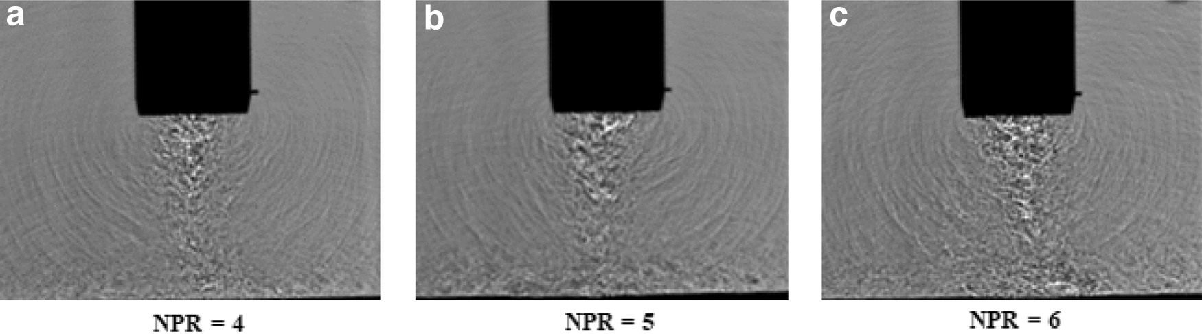
Instantaneous shadowgraph images of the baseline (without control) jet at h/dt = 6.
A combination of flow separation and unsteady shock interactions in the nozzle resulted in strong jet flapping. The image also reveals relatively less intense acoustic disturbances traveling upstream from the impingement point on the ground plane, where a high-pressure fluctuation zone develops due to jet-surface interaction.15,18,19 These waves seem to exhibit a shorter wavelength, which corresponds to a higher frequency than the acoustic waves that originate at the nozzle exit.
On the other hand, for the baseline flow at NPR = 5 and 6 (Fig. 5b, c), it can be observed that the flow features are similar to those at NPR = 4, such that vigorous jet flapping is evident with a modest change in terms of nozzle fullness. If one compares all the cases, it is observed that as the NPR increases for the baseline jet, the onset of flow separation inside the nozzle is pushed axially downstream within the diverging section of the nozzle, whereas the flow remains highly over-expanded and the unsteady jet-flapping is sustained.
Figure 6a represents the flow features associated with the activation of microjets at NPR = 4. It is seen that the presence of microjets shows minimal effect in improving the flow behavior in terms of oscillations and jet diameter. However, when the microjets are activated at NPR = 5 (Fig. 6b), the jet diameter increases significantly at the nozzle exit compared with the baseline case. At NPR = 6 (Fig. 6c), the activation of the microjets leads to a dramatic increase in jet diameter at the nozzle exit, and the reduction of intense jet-flapping is evident. This suggests that the activation of microjets effectively increases the jet diameter and produces a relatively stable flow at NPR = 5 and 6, as the relative position of the azimuthal microjet array is suitable to the location of flow separation occurring within the nozzle. It is expected that the microjets increase the momentum of the boundary layer and therefore delay flow separation. Similar results in terms of the effectiveness of active flow control for NPR = 5 and 6 were found in previous free jet studies 6 where the use of microjets inside the nozzle made the velocity profile fuller and streamwise velocity gradients more gradual at the nozzle exit. Careful examination of the shadowgraph images also suggests that, with the activation of the microjets, the intensity of acoustic waves was significantly reduced. This result is essential for the structural integrity and safety of the nozzle in terms of acoustic emission in the full-scale application. These qualitative results warrant quantitative measurements, discussed in the following sections.
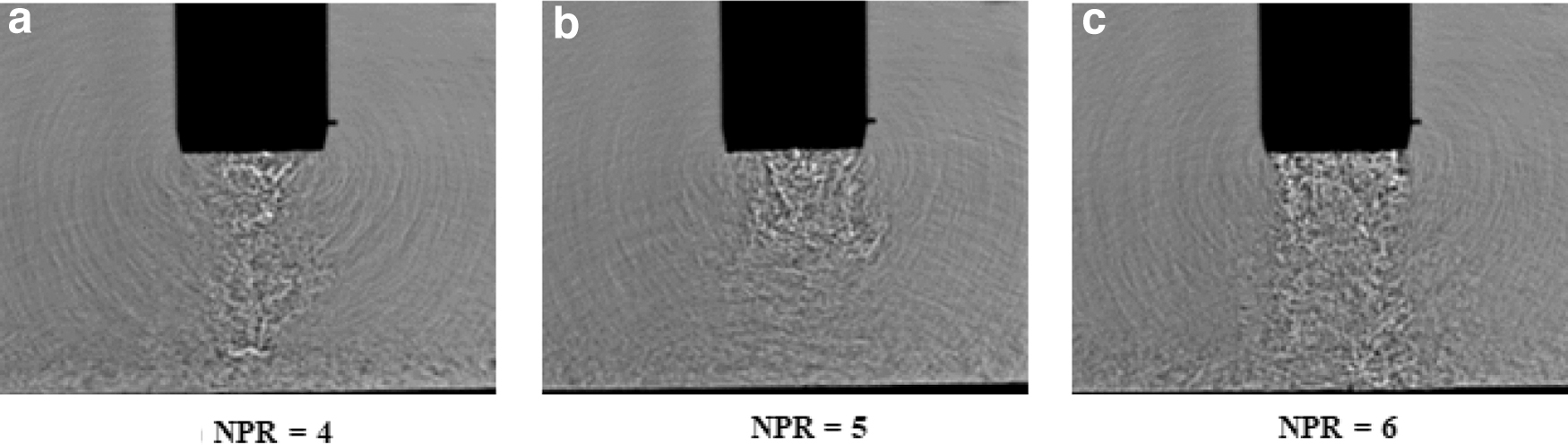
Instantaneous shadowgraph images of the jet with control at h/dt = 6.
Static Pressure Measurements on the Impingement Surface
The mean surface properties of the impinging jet are presented in this section to understand the pressure recovery and flow behavior on the impingement surface (ground plane). As mentioned in the experimental setup, static pressure measurements were carried out on the impingement surface by using 16 pressure taps placed in a radial array. Nozzle to ground plane distance and NPR were varied to get the pressure distribution on the ground plane. The local pressure of each port is presented in terms of the coefficient of pressure (Cp), as defined in Equation 1. The fully expanded jet Mach number (M) was calculated at the particular NPR by using the relation in Equation 2.
Effect of NPR
Figure 7a presents the static pressure distributions on the ground plane for NPR = 4 at different h/dt. The ordinate of the axis represents the radial location of each port on the ground plane, nondimensionalized with the nozzle throat diameter dt. The R/dt = 0 corresponds to the impingement point. Although the data were collected at only positive R/dt values, negative R/dt values are mirrored, assuming a symmetric jet, centered at R/dt = 0. Symmetry was confirmed in the experiments by making measurements on the other side of the impingement point. The results indicate that the mean pressure distribution roughly exhibits a Gaussian distribution over the plate surface. The geometric center of the jet impingement point corresponds to maximum pressure recovery that starts to drop in the radial direction. The drop in the pressure is due to the fact that after jet impingement, the flow begins to accelerate along the wall. Further downstream in the wall jet, the pressure coefficient attains a value of zero, as the pressure in the wall jet reaches atmospheric pressure. A drop in the magnitude of Cp along the radial direction between R/dt = 0 and 2 is also observed, as the nozzle to ground distance is increased due to ambient fluid mixing and dissipation before the jet impinges on the ground plane.
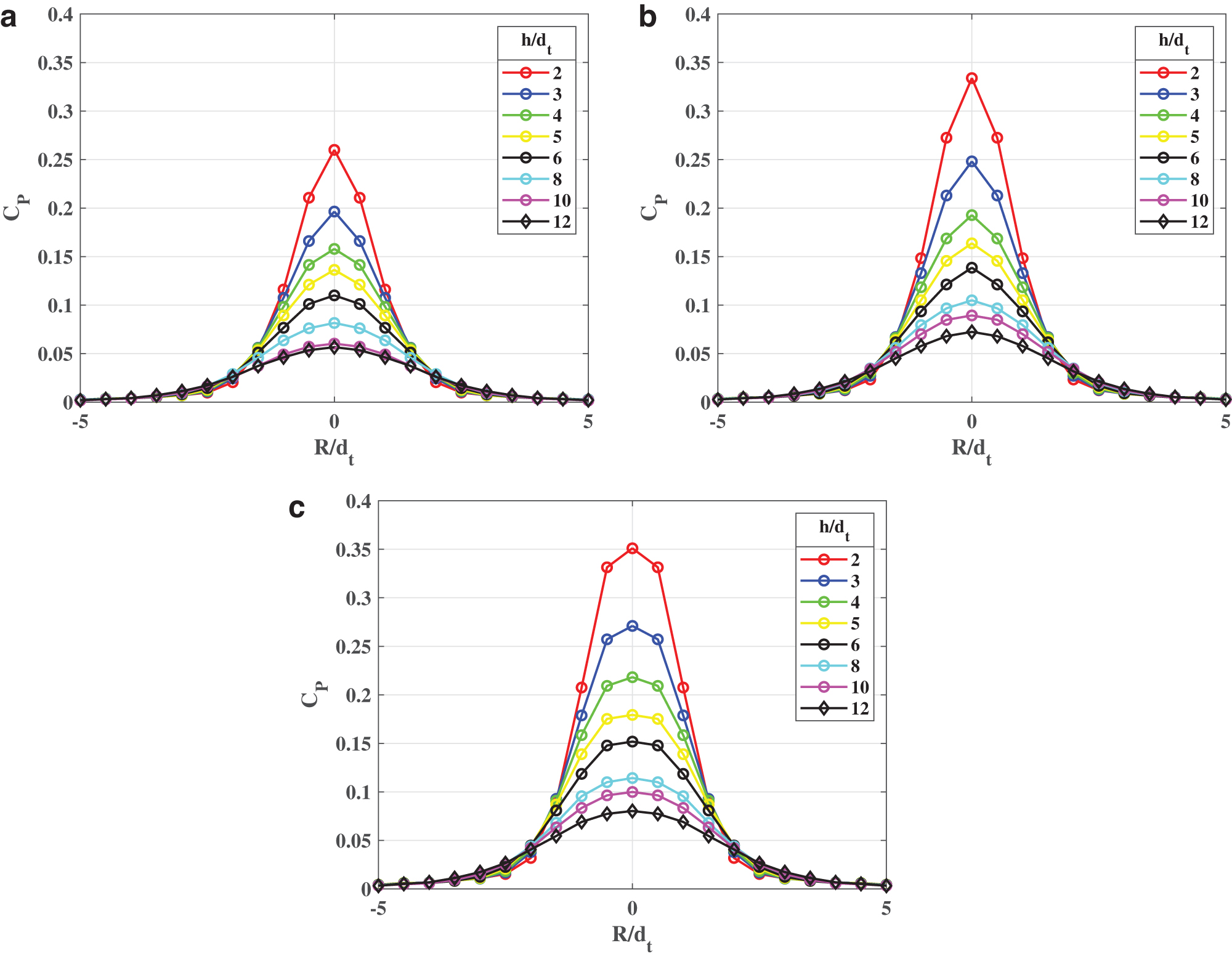
Pressure distributions on the impingement surface for the baseline jet.
For NPR = 5 and 6 (Fig. 7b, c), the pressure distribution is similar to NPR = 4, exhibiting the classical “normal jet impingement” behavior with the central peak at the impingement point for all h/dt and a decrease in magnitude for ports further away from the center. It is also seen from Figure 7a–c that an increase in NPR from 4 to 6 leads to a rise in pressure coefficient between R/dt = 0 and 2, due to an increase in the jet momentum. At shorter impingement heights, an increase in NPR also appears to have widened the pressure distribution, suggesting an increase in the jet diameter at the nozzle exit.
To generalize the effects of h/dt on the baseline jet, the impingement point pressures (at R/dt = 0) are plotted in terms of Cp for different impingement heights at NPR = 4, 5, and 6, as shown in Figure 8. The maximum value of Cp is achieved at NPR = 6 followed by NPR = 5 and 4, emphasizing that Cp is a function of NPR. Further, the pressures show a gradual decline in magnitude with increasing h/dt at all the NPR values. The nozzle exit is about 4.5dt downstream of the nozzle throat and the jet experiences flow separation inside the nozzle, which results in the lack of measurements in the jet potential core. Downstream of the nozzle exit, the momentum of the jet reduces continuously as it interacts with the ambient air before it impinges on the ground surface.
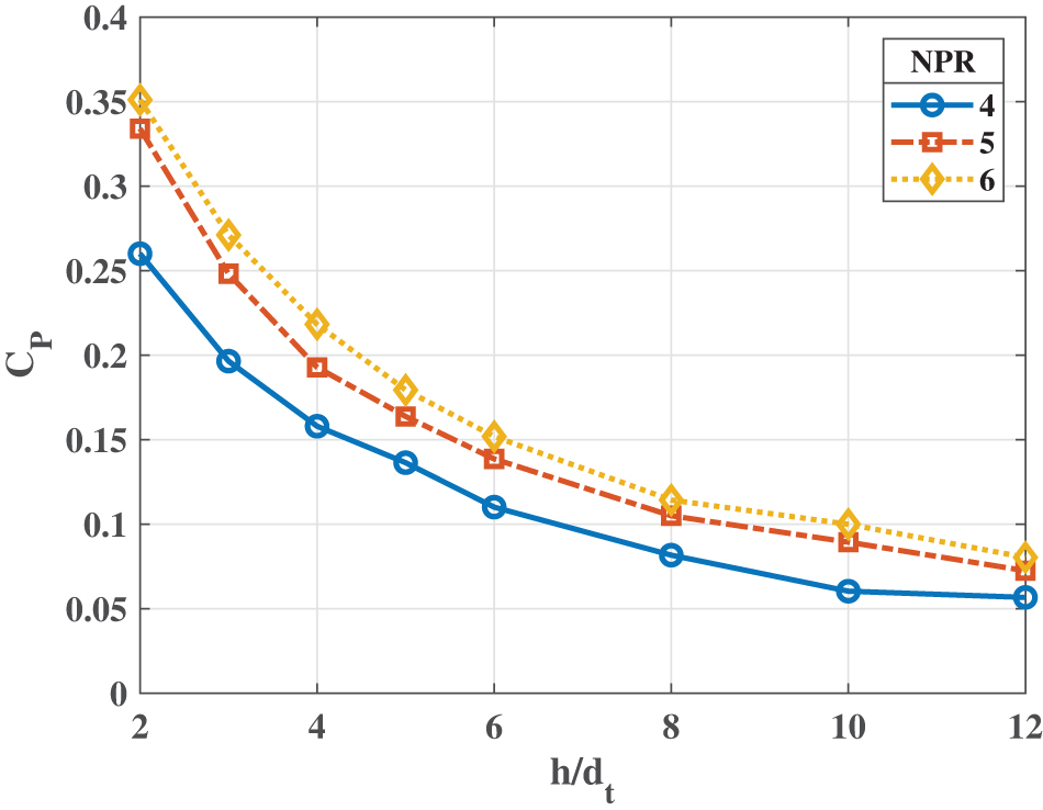
Effect of nozzle standoff distance on Cp at impingement point. Color images are available online.
Effect of microjet control
Khobragade et al. 6 confirmed that the flow separation occurs downstream of the throat for the similar NPRs tested. The azimuthal array of microjets were positioned at a location upstream of the flow separation at all the NPRs, for flow control. Figure 9a represents the pressure distribution at NPR = 4 with the microjets turned on. It must be noted that the pressure distribution is similar to the baseline case at NPR = 4, with a maximum Cp value of around 0.27 in both cases suggesting that the flow control has minimal influence on flow properties at this NPR. This was also evident from shadowgraph snapshots. The possible explanation of NPR = 4 remaining unaffected by microjet injection is that the flow separated near the microjet injection location, resulting in undeveloped vortices and therefore, the control is not that effective.

Surface pressure distributions on the impingement surface with control.
At NPR = 5 with flow control, seen in Figure 9b, the pressure profile exhibits no sharp central peak like at NPR = 4 and the pressure loads on the ground plane are distributed over a larger surface area. The Cp values are significantly lower at the impingement point in the presence of the flow control, and the pressure distribution closely resembles a top-hat profile. One can surmise that there is an increase in the jet area at the nozzle exit and therefore, a gradual and uniform pressure recovery over the rest of the pressure ports. The increase in the area of the jet due to activation of the micro-jets can be explained as follows: As the microjets are injected in the cross-flow, they create a variety of structures, including a counter-rotating vortex pair, resulting in the generation of streamwise vortices downstream of the injection location.6,15 This leads to increased mixing between the free-stream fluid and the low momentum near-wall fluid, resulting in a relatively fuller jet profile and jet width at the nozzle exit.
At NPR = 6 with flow control (Fig. 9c), from h/dt = 4 onward, the pressure distribution is similar to NPR = 5 with flow control, where a nearly top-hat profile is exhibited, although with higher strengths due to larger jet momentum relative to NPR = 5. However, the flow seems to show unexpected behavior at h/dt = 2 and 3, where the peak pressure magnitude is no longer at the center but rather slightly offset by a certain radial distance. This interesting behavior can be attributed to two possible reasons. First, the microjet control brings the main jet near the nozzle wall region due to flow attachment and shifts the main jet toward the wall region, thereby moving the jet core.
Another possibility is the presence of a stagnation bubble in the impingement region. The stagnation bubble comprises a recirculation region, which prevents the jet from directly impacting the surface at the center while directing the flow to a certain radial distance away from the center. In the past, various researchers have proposed theories as to what contributes to the presence of a stagnation bubble.15,20,21 One of the leading theories suggests that the presence of shocks inside the primary jet and its interaction with the plate shock contributes to the intermittent formation and dissipation of the stagnation bubble. Kalghatgi and Hunt 21 also proposed that incorrect nozzle design and surface imperfections contribute to the initiation of a stagnation bubble. In the present study, the shock theory can be discarded, given that the flow is subsonic past the nozzle exit, which is apparent from the absence of shocks in the shadowgraph images of the jet. Therefore, the issue remains elusive and warrants detailed flowfield studies inside the nozzle.
The pressure reduction and redistribution in the radial direction observed due to the application of flow control at NPR = 5 and 6 shown in Figure 10a and b, respectively could also be related to the changes in streamwise velocity distribution at the nozzle exit, as measured by Khobragade et al. 6 and shown in Figure 10c. The reduction in the centerline velocity and a fuller nozzle at the nozzle exit due to flow control is visible. This translates to the reduced total pressure in the impingement region and therefore reduced loading on the impinging surface.
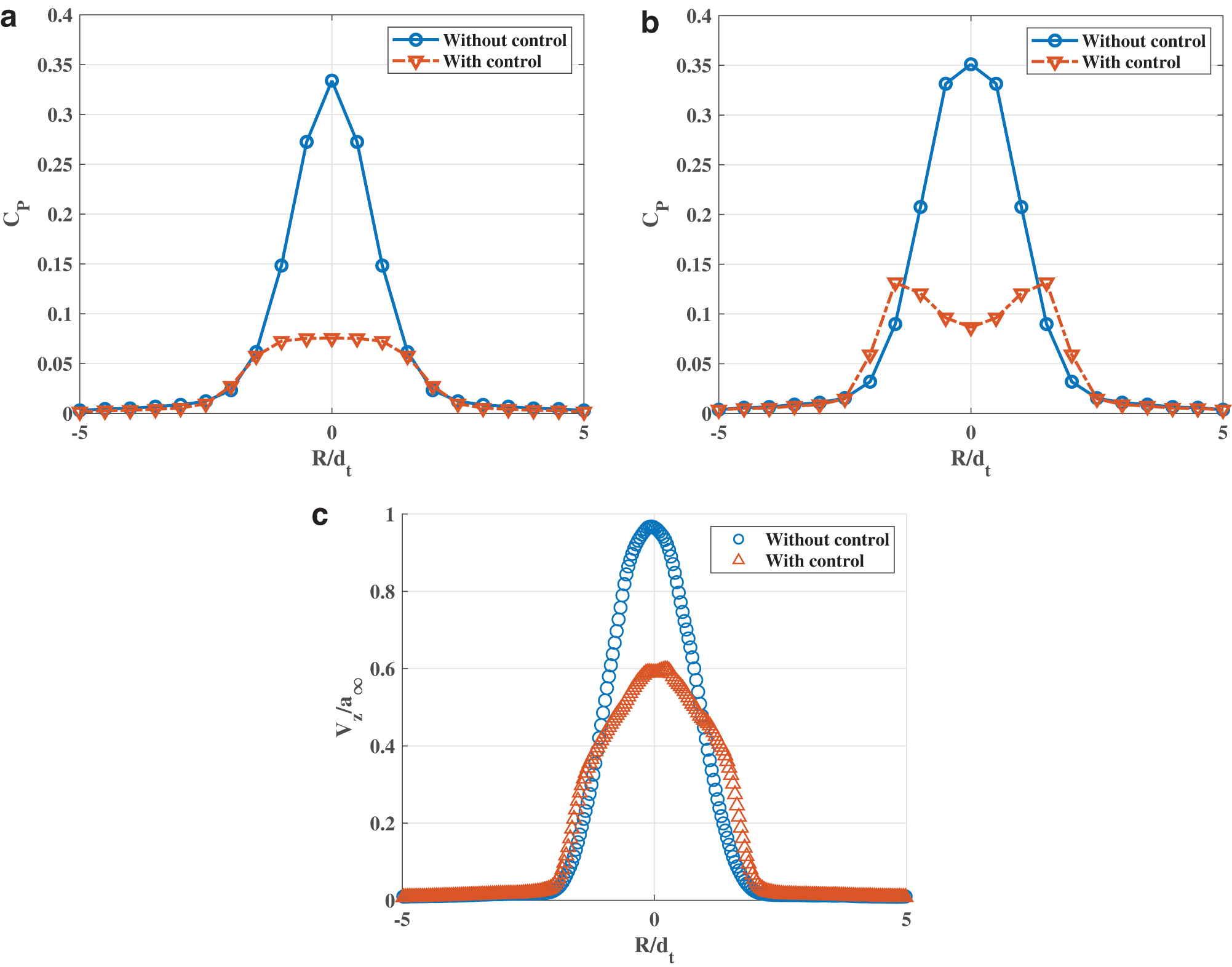
Effect of microjet control on surface pressure distributions.
Unsteady Pressure Fluctuations on the Impingement Surface and Nearfield Acoustics
Effect of NPR
Unsteady pressure measurements were made at the ground plane at 2 radial locations corresponding to R/dt = 0 and 4.25 with respect to the jet centerline. It is well documented that unsteady pressure fluctuations play a substantial role in quantifying the unsteady loads experienced at the impingement surface. Simultaneous, unsteady pressure, and microphone measurements were recorded, as shown in Figure 11 for NPR = 4 and 6. The intensity of pressure fluctuations on the ground plane and nearfield acoustic measurements at y = 30dt were quantified in terms of Prms expressed in dB with a Pref of 20 μPa. The pressure fluctuation intensities for NPR 4 are shown in Figure 11a. At each h/dt, the maximum fluctuation intensity is recorded on the ground plane at R/dt = 0, corresponding to impingement point, followed by those at R/dt = 4.25, which relates to the wall jet region. The magnitudes are almost 20 dB lower in the nearfield region measured by the microphone. The unsteady pressure fluctuations demonstrate a similar trend as that observed for the mean pressure coefficient, with the highest Prms values measured at the impingement point and a drop in the values at the adjacent radial ports. The unsteady pressures recorded in the current measurements resemble certain trends reported in supersonic impinging jet literature,11,15 such as the decrease in unsteadiness levels with an increase in impingement height and along the radial direction away from the jet centerline. Similar trends are observed at NPR = 6, as seen in Figure 11b. However, Prms and overall sound pressure level (OASPL) at NPR = 6 appear to be slightly higher. A comparison of these parameters is carried out in Figure 12, over the range of impingement heights tested.
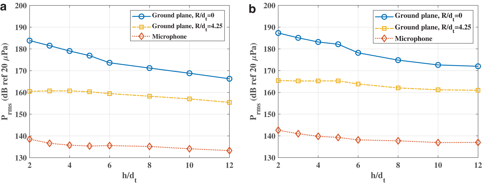
Pressure fluctuations measured on the ground plane and the nearfield acoustics for the baseline jet.
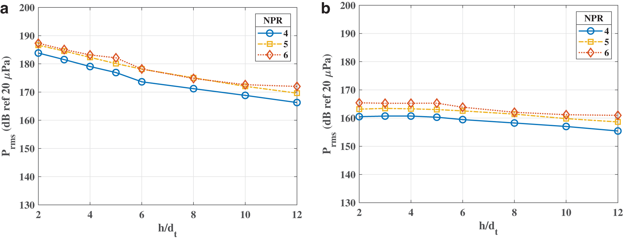
Effect of NPR and impingement height on pressure fluctuation amplitudes, in the absence of flow control.
Figure 12a represents the effect of NPR on the pressure fluctuations at the impingement point. High-pressure fluctuation intensities (in the range of 167–187 dB) are apparent in all three NPR cases irrespective of the impingement height. The fluctuation intensities thus measured also assert the unsteadiness caused due to the flapping of the jet plume itself, observed in the shadowgraph images (Fig. 5). Increasing the NPR from 4 to 5 increases pressure fluctuations by as much as 4 dB, whereas a further increase of NPR to 6 shows marginal effects. These results suggest a strong dependence of pressure fluctuation intensities on NPR, indicating the stabilization of the jet at higher NPR values. As observed earlier, an increase in the h/dt decreases the pressure fluctuations for all the NPR cases. The maximum intensity of pressure fluctuations is observed to be about 187 dB at h/dt = 2 for NPR = 6 and decreases in magnitude by about 14 dB at h/dt = 12. The pressure fluctuations measured in the wall-jet region, as seen in Figure 12b, are similar to the impingement point region, although with a weaker dependence on h/dt.
On the other hand, OASPL recorded by the nearfield microphone, as shown in Figure 13, also exhibit a strong dependence on NPR and a weak dependence on h/dt. An increase of NPR from 4 to 6 results in amplification of nearfield noise levels. These high acoustic emission levels are a health hazard to the personnel and detrimental to the nearby structures.

Effect of NPR and impingement height on OASPL. OASPL, overall sound pressure levels. Color images are available online.
Figure 14 represents the narrow-band spectra measured at the ground plane at the impingement point, in the wall jet region and the nearfield region corresponding to NPR = 6 and h/dt = 5 for the baseline jet. The spectra at all three measurement locations are of broadband without any dominant peaks related to impinging or screech tones. The absence of any visible shocks in the shadowgraph images, combined with the lack of any tones in the spectra, suggests that the flow at the nozzle exit is likely to be subsonic, possibly below Mach 0.7, as has been proposed by previous studies.22,23 The sources of noise leading to the spectral signature observed in the present study are composed of two different sources. One source is the turbulent mixing of the jet, and the second source is the acoustics generated due to the jet impingement. This behavior is in contrast with the supersonic jet impingement noise, which constitutes additional sources such as the broadband-associated shock noise, screech for a nonideally expanded jet, and impingement tones. 24

Frequency spectra of unsteady pressures and nearfield noise. Color images are available online.
In the present case, the maximum broadband noise corresponds to the impingement point followed by the wall jet and nearfield region. At the impingement point, pressure fluctuation levels gradually decrease with an increase in frequency. In the case of the wall jet region, a unique feature, a low-frequency broadband hump, is visible, spanning from 500 Hz to 3 kHz. The nearfield microphone spectra are also broadband in nature; however, the magnitude of pressure fluctuation levels remains nearly the same over a wide range of frequencies. The spectra measured at different locations suggest that an effective control technique has to work over a broadband range of frequencies.
To investigate the effect of distance between the nozzle exit and the ground plane, acoustic spectra for the baseline jet operating at NPR = 6 and impingement distance of h/dt = 2, 4, and 10 are shown in Figure 15. It may be observed that as the ground plane moves away from the nozzle exit, the magnitude of broadband noise decreases gradually, indicating the influence of the ground plane on the nearfield noise levels.
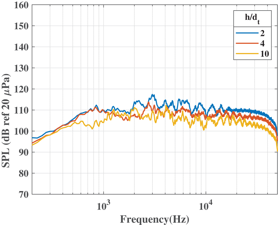
Effect of ground plane distance on the nearfield acoustic spectra. Color images are available online.
Effect of microjet control
The effectiveness of flow control is explored in terms of the changes in the unsteady pressures and noise levels over different operating conditions and impingement heights. Figure 16a presents the effectiveness of microjet control at the impingement location for various NPRs. The abscissa represents the nozzle to impingement plate distance whereas the ordinate represents ΔPrms, the difference in pressure fluctuations with and without control. At NPR = 4, microjet injection leads to a nearly constant reduction of about 1–2 dB at all impingement heights. However, as much as 12 dB reduction in the noise levels is observed with microjet control at lower h/dt for NPR 5 and 6. At larger h/dt, the ΔPrms gradually reduce to the value of 6 dB for NPR = 5, and the reduction is quite sharp at NPR 6. Similarly, Figure 16b represents the effectiveness of the microjet control in reducing nearfield noise in terms of ΔOASPL (the difference between with and without control cases) for different NPR and h/dt conditions. A reduction of more than 3–4 dB is achieved at all h/dt for NPR = 5 and 6 except for NPR 4, where the effectiveness is marginal.
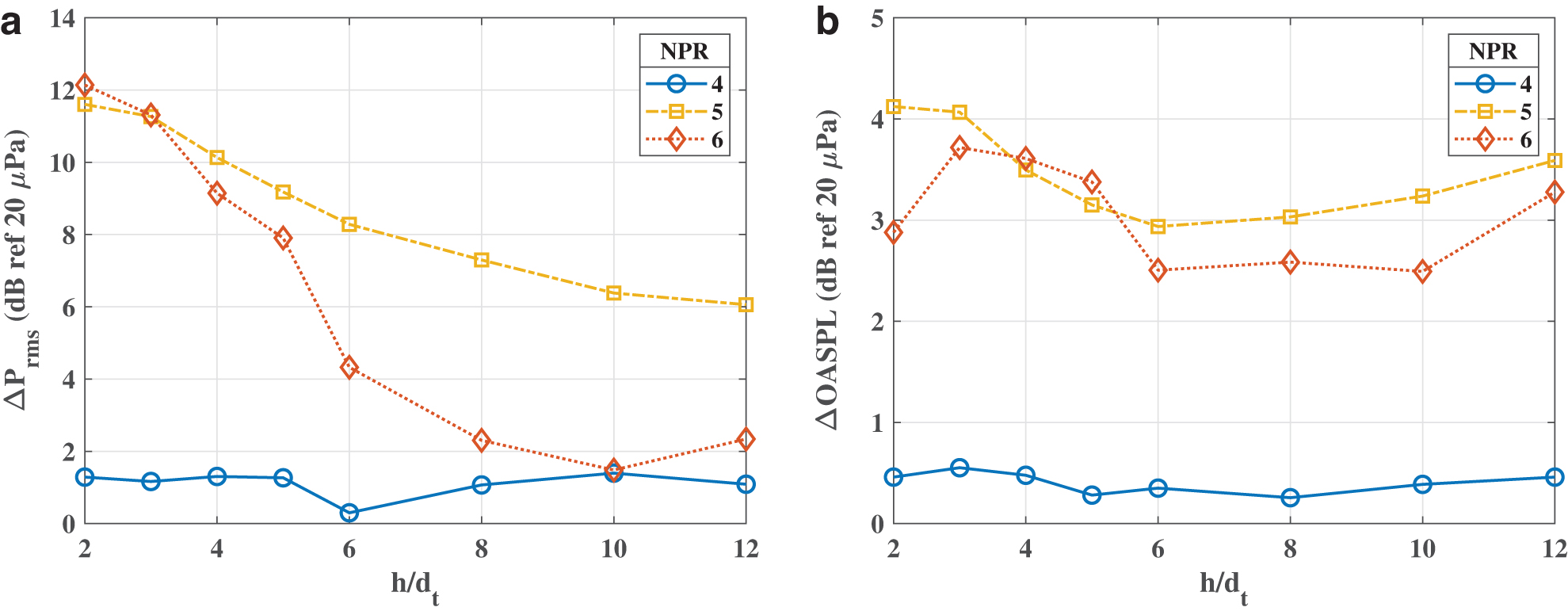
Effectiveness of microjets in terms of change in overall unsteadiness levels.
Figure 17 represents the effectiveness of microjet control in reducing pressure fluctuations at the ground plane and noise reduction in the nearfield region for NPR = 6 at h/dt = 2. The results show a significant reduction (a maximum of 15 dB at low frequencies) in pressure fluctuations at the impingement point over a broad range of frequencies. However, in the wall jet region, the reduction in pressure fluctuations is about 1–3 dB over the range of frequencies. Similarly, there is a reduction in nearfield acoustic levels with the microjet control.

Microjet effectiveness in terms of spectra.
The results cited earlier indicate a few interesting features of microjet-based flow control, namely
The microjet flow control alters the global flowfield of the jet, thereby reducing both the pressure fluctuations on the ground plane and the acoustics in the nearfield region.
The effectiveness of microjet control depends on both the NPR and h/dt, which indicates that it is most effective when the baseline jet is highly unsteady and pressure fluctuation levels are high, such as NPR = 5, 6 and small h/dt positions.
The effectiveness of microjet control is sensitive to the position of microjets to the location of flow separation inside the nozzle. Microjet control is effective if the flow separation location is slightly downstream of the microjet array location (NPR = 5 and 6). This suggests that if the flow separation location of a particular rocket nozzle operating at a certain condition is known a priori, one can tailor the position of microjet flow control for maximum effectiveness.
Conclusions
The present work investigated the flow and acoustic characteristics of an impinging jet flow generated by a Mach 4 axisymmetric C-D nozzle operating at highly over-expanded jet conditions that emulates its application in reusable rockets/boosters during vertical liftoff or landing. The jet was issued at isothermal conditions, and the flowfield was qualitatively analyzed by using the shadowgraph technique. Static and unsteady surface pressure measurements were performed to understand the mean and dynamic loading on the ground plane due to the impinging jet. Nearfield acoustic measurements at the fixed location relative to the nozzle were also employed to understand the relationship between an acoustic field with increasing NPR and nozzle standoff distances. Lastly, the effect of microjet-based control was also studied in an attempt to reduce the unsteady loading on the impingement surface and nearfield noise levels. The mean pressure measurements show a Gaussian profile in general, peaking at the center and gradually decreasing with increasing radial distance on the ground, indicating “normal impingement.” The peak magnitude at the impingement point decreases with an increasing nozzle standoff distance. In general, Prms and OASPL increase as the distance between the ground plane and nozzle is decreased, reaching a peak value as high as 187 and 145 dB, respectively. The spectra are of the broadband type, with high energy levels over a wide range of frequencies. The use of microjet-based flow control makes the jet fuller and relatively stable as compared with the baseline jet. Further, microjets significantly decrease the unsteady loads on the ground plane (up to 12 dB) and nearfield OASPL (up to 5 dB), demonstrating its effectiveness.
Although the study provides useful information in understanding the fundamental flow physics and acoustic characteristics of the over-expanded impinging jet, some questions remain unanswered. For example, what is the true extent of the effectiveness of the microjet and its corresponding unique pressure profile? To answer this, the authors plan on studying impinging jets at an even higher nozzle pressure and TRs. Therefore, further investigations with the help of diagnostic tools such as PIV and Pressure Sensitive Paint will further enhance understanding of the impinging jet issued from a rocket nozzle.
Footnotes
ACKNOWLEDGMENTS
The authors acknowledge the administrative and technical support of Ken Davidian and Nickolas Demidovich. The authors would also like to thank Jonas Gustavsson and Karthikeyan Natarajan for their valuable insights and suggestions.
Author Disclosure Statement
No competing financial interests exist.
Funding Information
This research is funded by the Federal Aviation Administration (FAA) Center of Excellence for Commercial Space Transportation (COE-CST) Co-operative Agreement 15-C-CST-FSU-05 as Task 325.