
Abstract
The aim of this work was to introduce high-resolution computed tomography (micro-CT) for scaffolds made from soft natural biomaterials, and to compare these data with the conventional techniques scanning electron microscopy and light microscopy. Collagen-based scaffolds were used as examples. Unlike mineralized tissues, collagen scaffolds do not provide enough X-ray attenuation for micro-CT imaging. Therefore, various metal-based contrast agents were applied and evaluated using two structurally distinct scaffolds, one with round pores and one with unidirectional lamellae. The optimal contrast techniques for obtaining high-resolution three-dimensional images were either a combination of osmium tetroxide and uranyl acetate, or a combination of uranyl acetate and lead citrate. The data obtained by micro-CT analysis were in line with data obtained by light and electron microscopy. However, small structures (less than a few μm) could not be visualized due to limitation of the spot size of the micro-CT apparatus. In conclusion, reliable three-dimensional images of scaffolds prepared from soft natural biomaterials can be obtained using appropriate contrast protocols. This extends the use of micro-CT analysis to soft materials, such as protein-based biomaterials.
Introduction
Researchers have employed micro-CT in the field of tissue engineering.6–8 The versatility of micro-CT has been demonstrated in the evaluation of scaffolds, because this single technique is capable of characterizing multiple aspects of the scaffolds. 6 Micro-CT enables to get three-dimensional (3D) images of the internal area of a sample, and a detailed 3D view of pores at any depth. 9 Further, different parameters may be calculated such as porosity, surface area to volume ratio, pore size, pore wall thickness, anisotropy, cross-sectional area, and permeability. 6 Micro-CT has been used for several polymer-based scaffolds that hold sufficient intrinsic contrast. For example, the internal geometry, pore network, and pore interconnectivity of poly-ɛ-caprolactone scaffolds have been determined 10 ; in addition, the porosity, surface area to volume ratio, and interconnectivity of scaffolds made from a copolymer of poly ethylene glycol, poly-ɛ-caprolactone, and polylactic acid have been evaluated. 6 Quantification of microarchitectural parameters, including volume fraction, density, thickness, spacing, and degree of anisotropy, of porous poly(L-lactide-co-DL-lactide) scaffolds with axially oriented macroporosity and random microporosity has also been reported. 7
Scaffolds based on natural proteins such as collagen do not have the intrinsic X-ray attenuation capacity to be imaged by 3D micro-CT. Consequently, additional contrast has to be imposed upon such scaffolds. The aim of this work was to introduce micro-CT for proteinaceous scaffolds as exemplified by collagen, and to compare results with those obtained by scanning electron microscopy and light microscopy. Two structurally different scaffold types were tested, one with round pores and one with unidirectional lamellae. Different heavy metal contrast agents were assessed to find useful radio-opaque contrast agents that allow the use of micro-CT imaging for collagen scaffolds in particular and protein-based scaffolds in general.
Materials and Methods
Collagen scaffolds
Collagen scaffolds were prepared as previously described. 11 Briefly, a collagen suspension was prepared by incubation of 0.9% purified insoluble type I collagen in 0.25 M acetic acid at 4°C for 16 h. The suspension was homogenized on ice, followed by deaeration by centrifugation at 525 g, resulting in the collagen suspension to be used for the scaffold.
Scaffolds with round pores were prepared by freezing 4 mL of collagen suspension per well of a six-well culture plate at −20°C. Scaffolds with unidirectional lamellae connected by thin struts (about 1–2 μm) were prepared using a temperature gradient between liquid nitrogen (−196°C) and ambient temperature. This induces a temperature gradient starting from the side of N2 (l) toward the ambient temperature, thus producing lamellar structures. The principle is essentially the same as described by Schoof et al. 12 The frozen collagen suspensions were then lyophilized to obtain dry scaffolds. Samples of approximately 5 × 5 × 5 mm were used for analysis.
Scaffold preparation for imaging
To obtain collagen scaffolds with appropriate contrast for micro-CT imaging, different contrast agents were used: osmium tetroxide, uranyl acetate, and lead citrate. The stains were selected based on contrast agents used in electron microscopy: first, because they bind to biological materials, and, second, because by being heavy metals they have the ability to apply contrast. In particular, uranyl acetate and lead citrate are used to stain collagen for electron microscopy.
13
All scaffolds were treated with different contrast agents in distilled water at 22°C, followed by three 20 min washings in distilled water. The applied procedures were as follows:
1% (w/v) osmium tetroxide for 24 h; 1% (w/v) osmium tetroxide for 6 days; 1% (w/v) lead citrate for 24 h; 2% (w/v) uranyl acetate for 24 h; 2% (w/v) uranyl acetate for 24 h, followed by three washings in distilled water for 20 min and 1% (w/v) lead citrate for 24 h; 1% (w/v) osmium tetroxide for 6 days, followed by three washings in distilled water for 20 min and 1% (w/v) lead citrate for 24 h; 1% (w/v) osmium tetroxide for 6 days, followed by three washings in distilled water for 20 min and 2% (w/v) uranyl acetate for 24 h; 1% (w/v) osmium tetroxide for 6 days, rinsed five times for 15 min with distilled water, followed by 1% (w/v) thiocarbohydrazide for 1 h, rinsed five times for 15 min with distilled water, and 1% osmium tetroxide for 1 h (treatment according to Kelly et al.
14
for enhanced contrast intensity due to increased binding of osmium tetroxide in a postincubation step
15
).
After each procedure, scaffolds were dehydrated in an ascending series of ethanol and critical point dried in a Polaron E3000 apparatus (Quorum Technologies, Newhaven, United Kingdom) using liquid CO2.
CT-scan imaging and data analysis
The samples were scanned using the SkyScan 1072 Micro-CT (SkyScan, Kontich, Belgium) with Feldkamp cone-beam reconstruction. NRecon V1.4.0 software was provided by SkyScan. The sample was mounted on a rotation stage in front of the X-ray source with Optosil (Heraeus, Armonk, NY). A high-resolution charge-coupled device with a resolution of 1024 × 1024 pixels was applied to detect the X-rays from the scanned samples and to store data. The following micro-CT settings were applied based on a pilot experiment: (1) the X-ray source was set to 47 kV and 142 μA resulting in a 6 μm spot size, (2) a relatively high magnification (125 ×, pixel size: 2.26 μm) was applied to detect the structures of interest, (3) a relatively low exposure time (1.9 s) was taken, (4) samples were rotated 180° with a rotation step of 0.45°, and (5) a filter was omitted. An optical 1 mm3 selection was taken in the middle of the scaffold. After acquisition of the images at all rotation steps, the raw data were reconstructed to provide axial picture cross sections. After cone-beam reconstruction, the raw data were converted to a 16-bit bit-mapped picture files with a resolution of 512 × 512 pixels. Using SkyScan's CT-analyzer v1.6 analyzing program, the pore size in the porous scaffolds and the distances between the lamellae in the unidirectional collagen samples were determined. Ten pores and the distance between 10 lamellae were measured automatically from a two-dimensional (2D) image at the largest diameter of the pore in the X and Y directions. 3D-Doctor V4.0 (Able Software, Lexington, MA) was used to create a final 3D model of the collagen sample. Model editing (e.g., rotating, editing, and transparency) was applied to optimize visualization of the collagen structures. Standardized software settings for scanning, cone-beam reconstruction, and gray-level thresholding were used in the projected and reconstructed files.
Scanning electron microscopy
Collagen scaffolds were mounted on stubs and sputtered with an ultrathin layer of gold in a Polaron E5100 Coating System (Quorum Technologies). Collagen scaffolds were studied with a Jeol (Tokyo, Japan) JSM-6310 SEM at an accelerating voltage of 15 kV.
Light microscopy
Scaffolds were fixed in 2.5% glutaraldehyde and 1% osmium tetroxide in 0.1 M phosphate buffer (pH 7.4) and embedded in epon. Sections of ∼1 μm thickness were cut with an ultramicrotome, mounted on glass slides, and stained with 2% (w/v) toluidine blue in 5% (w/v) aqueous sodium tetraborate · 10 H2O for 20 s. Sections were examined and photographed with a Leica (Wetzlar, Germany) DM 6000B light microscope.
Results
Two structurally different types of scaffolds were analyzed: scaffolds with large (∼100 μm) round pores and scaffolds with unidirectional lamellae. The samples were rotated 180° with a scanning period of 0.45°/1.9 s without the use of an additional filter. The average scanning time per sample was 1 h.
Scaffolds with random round pores were visualized with different contrast enhancement techniques. Table 1 gives an overview of the protocols used and the contrast obtained as determined by visual inspection. Without any contrasting method, collagen scaffolds could not be visualized (data not shown). Moderate contrast enhancement in combination with a homogeneous distribution was achieved by the use of 2% uranyl acetate for 1 day, whereas the use of 1% osmium tetroxide for 1 day resulted in a lower signal, thus lower contrast (Fig. 1B, E). However, when scaffolds were impregnated with osmium tetroxide for 6 days, moderate contrast was achieved. In addition, thiocarbohydrazide was used to produce more contrast, but still only moderate contrast was obtained. The use of lead citrate gave poor results. A combination of contrast agents proved to be effective. The most suitable contrast techniques for visualization of collagen scaffolds were a combination of 1% osmium tetroxide for 6 days and 2% uranyl acetate for 1 day (Fig. 1A, D) or a combination of 2% uranyl acetate for 1 day and 1% lead citrate for 1 day. These good contrast methods lead to most detail in the 3D reconstructions, whereas a weak contrasting protocol resulted in a poor 3D reconstruction (Fig. 1C, F).

Effect of three contrast procedures on the attenuation of X-rays by porous collagenous scaffolds in a micro-CT setting. (
Two movies (see Supplemental Movies roundpores.avi and unidirectionallamellae.avi, available online at

Snapshot still images taken from (
Using contrasting protocol 6, initial measurements were made, and the pore diameter could be determined. A representative part of the whole samples of collagen scaffolds with round pores and unidirectional lamellae was reconstructed using a stack of 2D images (see Fig. 3B for a scaffold with round pores and Fig. 3E for a unidirectional scaffold). Micro-CT images of collagen scaffolds with round pores revealed pore sizes of ∼100 μm (Fig. 3A), whereas the distance between the lamellae in unidirectional scaffolds was around 50 μm (Fig. 3D). With the use of the whole file series of all gray values from the scaffold material compared to the radio opaque air, the porosity of the scaffold was estimated to be 86 ± 5% (n = 5 ± SD). Finally, the data obtained by micro-CT were compared to data acquired by scanning electron microscopy and by light microscopy. The pore diameter in scaffolds with round pores was generally about 100 μm for both methodologies, similar to micro-CT data (Fig. 4A–C). Scaffolds with unidirectional lamellae examined with scanning electron microscopy showed a distance between the lamellae of 51 ± 11 μm (n = 50 ± SD), similar to micro-CT. Using light microscopy, this distance was 64 ± 9 μm (n = 50 ± SD) (Fig. 4D–F). However, the micro-CT image of the unidirectional scaffold did not reflect the complete structure of the scaffold; the small struts in between the lamellae (generally 1–2 μm) were too thin to be visualized, because they are below the resolution limit of the equipment, which is about 6 μm using the applied settings.
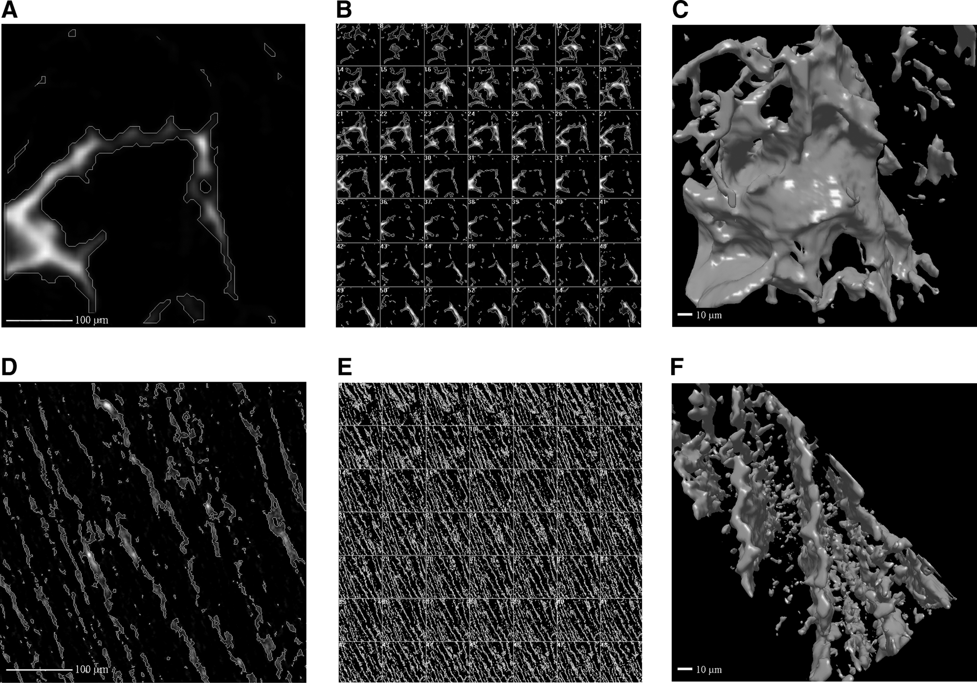
Micro-CT analysis of two different contrast-enhanced collagenous scaffolds. (
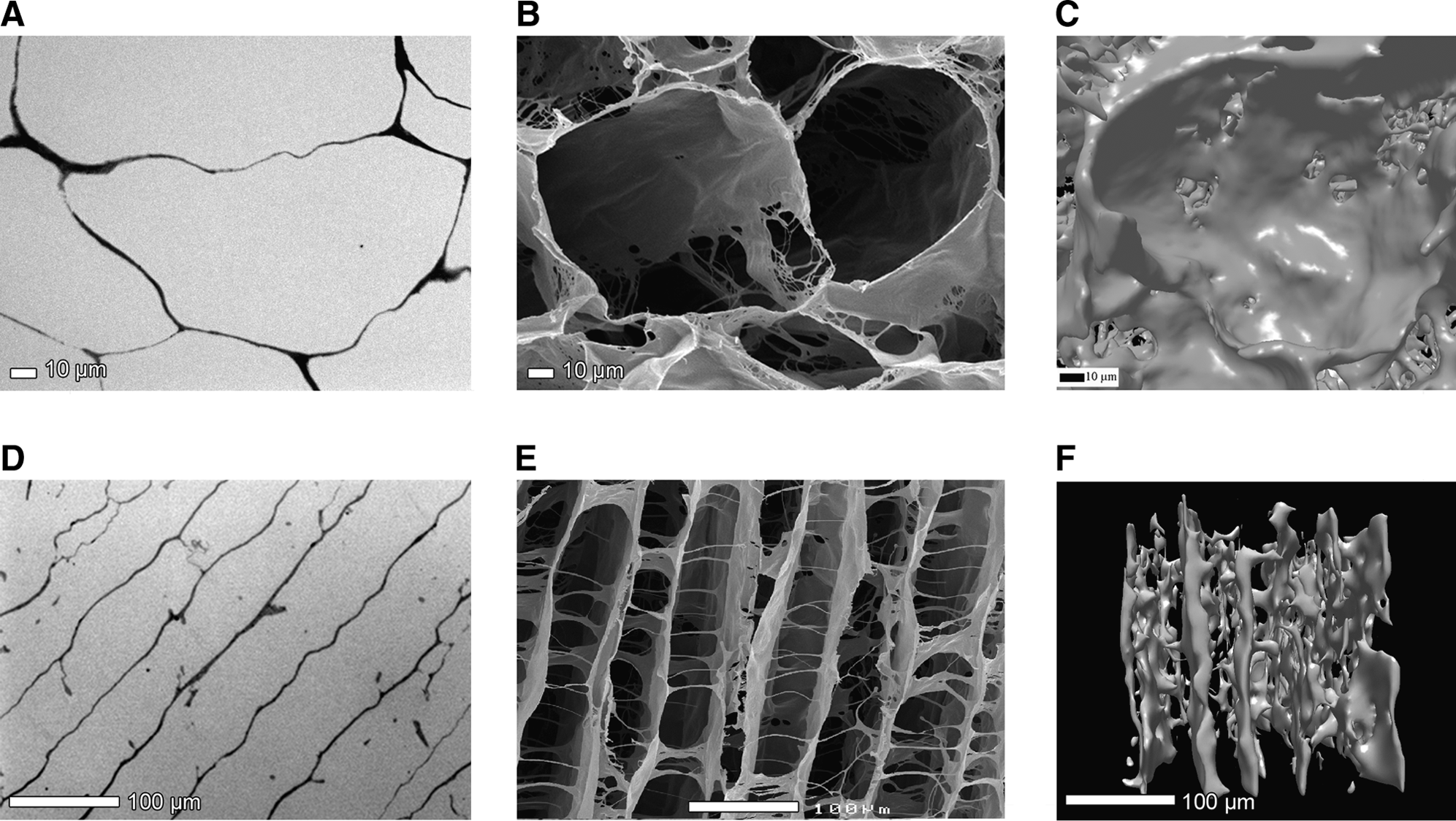
Comparison of images obtained using micro-CT with those obtained by light and electron microscopy pictures of random (
Discussion
The 3D architecture of the scaffold is of great importance for the behavior of cells. Cells behave differently in a 3D environment compared to a 2D structure.16–19 Therefore, effective scaffold assessment techniques are required to evaluate the structural characteristics of scaffolds. Among these techniques SEM analysis is most popular for soft tissue, whereas micro-CT is generally used for hard tissue (such as bone).3–5,10
We here show imaging of collagen scaffolds by means of micro-CT. Using metal-based contrast enhancement methods, the structure of collagen scaffolds was visualized. In this study, we only looked at porosity, but with the appropriate software, it is possible to determine other parameters, like density and interconnectivity, for soft scaffolds. When the structures in the collagen scaffolds are not too small, the 3D data sets obtained using micro-CT provide information about the sample's structure that is comparable to complementary methods such as light and electron microscopy, but with the obvious advantage of 3D of the whole specimen.20–23 We were unable to visualize collagen scaffolds without contrast agents. Buttafoco et al. 24 did succeed in micro-CT visualization of collagen–elastin tubes without contrast agents. This difference with our scaffolds cannot be explained because the presence of thick elastin fibers does not provide more image contrast.
When structures are too small, one encounters the instrumental limitations of the micro-CT equipment. The estimated porosity may thus be overvalued because of this. Nano-CT may be a solution to this problem. The theoretical instrumental limitation of the nano-CT apparatus is 200 nm compared to 2 μm for the micro-CT apparatus. 25
Drawbacks of micro-CT are the difficulty of thresholding, beam hardening, and the need for specialized software to quantify certain parameters (e.g., interconnectivity). 6 Before 3D modeling, the crucial step is to separate scaffold material from background (performed by thresholding the image gray level 9 ), which affects the subsequent visualization. When too much thresholding is applied, scaffold material is undervalued. Beam hardening is known as the high exposure of the scaffold center as a result of scaffold attenuation of the lower energy rays of the used polychromatic X-ray beam. As a consequence, thresholding is no longer dependent solely on radiodensity, but also on specimen size.26,27
Although micro-CT still faces some problems when used for scaffolds made from soft natural biomaterials (i.e., limitation to visualize small structures), this method is able to provide a 3D reconstruction of the specimen in little time and with little processing, whereas techniques like scanning electron microscopy and light microscopy are very laborious. In addition, it is possible to scan a large specimen with good morphology of the whole scaffold. It should be seen as complementary to other methods.
Conclusion
Using specific contrasting protocols, we showed the potential of imaging soft, proteinaceous materials by micro-CT. The most suitable contrast techniques for visualization of collagen scaffolds were a combination of 1% osmium tetroxide for 6 days + 2% uranyl acetate for 1 day, and a combination of 2% uranyl acetate for 1 day + 1% lead citrate for 1 day. A drawback is that small details (less than few μm, e.g., struts in unidirectional scaffolds) cannot be observed with micro-CT. For better resolution, nano-CT is needed.
Footnotes
Acknowledgments
This work was financially supported by EU-FP6 project EuroSTEC (soft tissue engineering for congenital birth defects in children; contract: LSHB-CT-2006-037409) and the Dutch Program for Tissue Engineering (DPTE6735).
Disclosure Statement
No competing financial interests exist.
References
Supplementary Material
Please find the following supplemental material available below.
For Open Access articles published under a Creative Commons License, all supplemental material carries the same license as the article it is associated with.
For non-Open Access articles published, all supplemental material carries a non-exclusive license, and permission requests for re-use of supplemental material or any part of supplemental material shall be sent directly to the copyright owner as specified in the copyright notice associated with the article.