




Abstract
A manufacturing process for fabricating off-the-shelf multilumen poly(ethylene glycol) (PEG)-based nerve guidance conduits (NGCs) was developed that included the use of stereolithography (SL). A rapid fabrication strategy for complex 3D scaffolds incorporated postprocessing with lyophilization and sterilization to preserve the scaffold, creating an implantable product with improved suturability. SL is easily adaptable to changes in scaffold design, is compatible with various materials and cells, and can be expanded for mass manufacture. The fabricated conduits were characterized using optical and scanning electron microscopy, and measurements of swelling ratio, dimensional swelling factor, resistance to compression, and coefficient of friction were performed. Water absorption curves showed that the conduits after lyophilization and sterilization return easily and rapidly to a swollen state when placed in an aqueous solution, successfully maintaining their original overall structure as required for implantation. Postprocessed conduits at the swollen state were less slippery and therefore easier to handle than those without postprocessing. Suture pullout experiments showed that NGCs fabricated with a higher concentration of PEG were better able to resist suture pullout. NGCs having a multilumen design demonstrated a better resistance to compression than a single-lumen design with an equivalent surface area, as well as a greater force required to collapse the design. Conduits fabricated with a higher PEG concentration were shown to have compressive resistances comparable to those of commercially available NGCs. The use of SL with PEG and the manufacturing process developed here shows promise for improving the current state of the art in peripheral nerve repair strategies.
Introduction
Recent tissue engineering (TE) work in the peripheral nervous system is focusing on the use of bioabsorbable, biodegradable materials, and incorporating both growth factors and cells into the conduit to overcome the current issues of tubular nerve repair and promote faster healing over longer lengths.1,4–8 Recent studies in nerve regeneration have also focused on the conduit's design, using multiple lumens to better mimic the natural structure of a nerve and provide a greater surface area for support cells and sprouting axons.13–18
Different techniques for fabricating tissue-engineered NGCs have been explored and developed with the technique dependent on the material used to fabricate the conduits. These include textile technologies, dipping of a substrate, solvent casting/particulate leaching techniques, and phase separation systems. In textile technologies, polyglycolic acid and chitosan in fiber form have been used to fabricate NGCs with tubular braiding machines and electrospinning devices.19,20 Poly-L-lactic acid (PLLA), copolymers of polylactide (both L-lactide and D-lactide) and polycaprolactone, or blends of PLLA with poly(lactic-co-glycolic acid) (PLGA) dissolved in either chloroform or methylene chloride have been used as the dipping solution, where cylindrical substrates (e.g., syringes and small polytetrafluoroethylene sheaths) are immersed to create single tubes and tubes with multiple channels.21,22 PLGA has been used to fabricate conduits combining injection molding and phase separation techniques, where a highly concentrated solution of the polymer is injected into a cylindrical mold, and then the solvent is removed by sublimation.13,15–17 PLLA, PLGA, and urethane-based polyglycolide-co-ε-caprolactone blends have been extruded into tubes with and without the use of salt particles to produce highly porous tubes via particle leaching.23–25 Glass tubes have been used as molds to create single- and multichannel tubes of hydroxyethyl methacrylate and chitin-based materials.14,26,27 Suspensions of alginate-chitosan and poly (D,L-lactic-co-ε-caprolactone) have been deposited into spinning mandrels to produce simple tubes. 28
In a different approach for the development of NGCs, decellularization treatments for allografts have been explored to avoid undesirable immune responses. Nerves, muscles, and small intestinal submucosa have been investigated as acellular allografts for nerve repair. These allografts have been pretreated with different growth factors or seeded with Schwann cells before implantation in a rat model. Acellular allografts have shown promising results, as the nerve grafts retained the extracellular structure of peripheral nerve tissue, the decellularization process yielded immunologically tolerated grafts, and, ultimately, the grafts with incorporated growth factors and cells supported regeneration.29,30 Still, decellularized grafts have the disadvantage of not being easily available, as decellularization protocols may take at least 48 h, complete decellularization must be demonstrated, and storing the grafts may compromise their regenerative ability.1,2
The characteristics of an optimal NGC are reviewed in several publications.1–9 Some key features important for the design of NGCs include being readily available, tear resistant, resistant to collapse in situ, easy to handle by the surgeon, suturable, sterilizable, biodegradable, tailorable for incorporating growth factors or cells if desired, and supporting cell growth. Further, having multiple intraluminal channels has emerged more recently as a potential benefit over a single-lumen NGC.
In this work, the rapid prototyping or additive manufacturing technology of stereolithography (SL) is explored for the fabrication of NGCs that have many of these features. It has been shown previously that SL is a unique technology with potential in TE as it can be used with photocrosslinkable biomaterials to create complex 3D tissue-engineered scaffolds.31–34 Here, we have designed an NGC to be fabricated with two important characteristics: a capped portion at each end that allows effective suturing of the damaged nerve stumps to the NGC, and a multilumen middle portion that provides a greater surface area for support cells and sprouting axons. The dimensions of the design (2.94 mm outside diameter [OD] and 1.72 mm inside diameter [ID], with seven 400-μm-diameter lumens) are the smallest permitted by the current SL system used for the fabrication, and these dimensions were established based on data found in the literature for peripheral nerve regeneration in a rat model. Photopolymerizable poly(ethylene glycol) (PEG), already in use for a variety of TE applications, including cell encapsulation,35,36 creation of synthetic extracellular matrix analogs,37,38 and formation of substrates with patterned arrays of immobilized proteins and/or cells,39,40 was used. A manufacturing process to fabricate off-the-shelf NGCs was developed. This manufacturing process involved the use of SL, which permits a rapid fabrication strategy for complex 3D scaffolds, and postprocessing stages of lyophilization and sterilization that preserve the scaffold, creating an implantable, off-the-shelf product with improved suturability. Fabricated conduits were characterized using optical and scanning electron microscopy, and the swelling ratio, dimensional swelling factor, and coefficient of friction were determined. Further, resistance to compression for multilumen and single-lumen NGCs as well as the suture retention ability were measured.
Materials and Methods
Photopolymer solution
Photocrosslinkable, commercially available PEG diacrylate (PEG-da, MW 3400; Laysan Bio, Inc.) was dissolved in HEPES-buffered saline at a concentration of 20 or 30 wt.%. The cytocompatible photoinitiator Irgacure 2959 (I-2959; Ciba Speciality Chemicals Corporation) was added to the photopolymer solution at a concentration of 0.5 wt.%. It has been demonstrated that I-2959 causes minimal toxicity over a broad range of cell types and allows for photopolymerization of thin layers.31,41
Apparatus
A 3D Systems Model 250/50 SL machine (3D Systems) equipped with a He-Cd laser (325 nm, 40 mW) was used for the fabrication of NGCs. The original setup of the SL machine was modified to fabricate complex 3D shapes. Details of the machine modifications for scaffold fabrication are described elsewhere. 42 Briefly, the modifications consisted of removing the original vat of material from the machine and using a self-aligning minivat setup at the center of the platform to contain the photopolymer solution. The elevator platform, originally used to support a part during its fabrication, was used to hold the minivat. The height of the platform was set at a distance where the laser beam was circular with a diameter of ∼250 μm.
Scaffold fabrication
Stereolithography
The SL process starts with the computer-aided design (CAD) of the desired 3D object in .stl format, followed by the preparation of build files with 3DLightyear™ (3D Systems). 3DLightyear™ generates the 2D slices of the 3D part that will be used for fabrication. This process is presented in detail elsewhere.31,43
For this study, the dimensions of the NGC in the CAD were 2.94 mm OD, 1.72 mm ID, with seven 400-μm-diameter lumens contained within the ID (see Fig. 1A). These dimensions were experimentally determined to be the smallest permitted by the SL system and PEG solutions used for the fabrication and within the range of those found in the literature for peripheral nerve regeneration in a rat model,13,23,25 taking into consideration the swelling of the material.42,43

Fabrication of nerve guidance conduits. (
To build a PEG-based structure in SL, the appropriate laser scan velocity required to photocrosslink the desired geometry has to be determined first. 43 The appropriate laser scan velocity is determined by crosslinking the desired 2D pattern composed of small features at different laser scan speeds and examining the patterns under a microscope for dimensional accuracy. For the NGC design, the pattern of the multilumen portion was crosslinked at different laser speeds, and the size of the lumens was measured from optical micrographs for each crosslinked pattern. The velocity at which the multilumen pattern crosslinked forming a gel with sufficient mechanical strength to be handled and imaged without severe deformation (i.e., it maintained its circular shape) and all the lumens were circular and closest to 400 μm in size was selected as the velocity to fabricate the scaffold (see Fig. 1B). It should be noted that different scan velocities to properly crosslink a scaffold using the method described above have been observed when using different batches of PEG-da.
For layered fabrication, consecutive layers were formed such that there was ∼300 μm of overlapping between layers to ensure effective interlayer bonding. As described elsewhere31,43 a strong interlayer bonding in layer-based additive manufacturing is achieved by overcuring one layer into the previously cured layer. When there is insufficient interlayer bonding, delamination occurs between layers. If the overcure is too great, geometric accuracy in the x–y plane suffers, resulting in loss of feature resolution. As a result, selecting the appropriate scanning energy is a trade-off between feature resolution and interlayer bonding.
Swelling
Fabricated NGCs were placed in phosphate-buffered saline (PBS; pH 7.4) for >48 h to allow the samples to reach equilibrium. PBS was changed twice to remove any photoinitiator and unreacted polymer that might leach out of the samples. The samples swelled in PBS, resulting in dimensional changes as expected.
Lyophilization
Freeze-drying (or lyophilization) of the conduits was performed by flash-freezing the conduits in liquid nitrogen, followed by drying under vacuum at −55°C for >12 h in a freeze-dry system (FreeZone 6; Labconco Corporation).
Sterilization
Once the conduits were lyophilized, they were placed individually in polystyrene tubes, and sealed in Tyvek pouches for sterilization in a low-temperature hydrogen peroxide plasma sterilizer (Sterrad 100S; Advanced Sterilization Products). The sterilization cycle ran for 47 min.
Characterization
Weight and dimensional changes
NGC samples, capped at one end only, were fabricated using SL to be characterized at each stage of the fabrication process. The samples were weighed using an analytical balance (Sartorius CP124S; Sartorius AG) and digital images of the samples were acquired using a stereomicroscope (MZ16; Leica Microsystems) equipped with a CCD camera (Retiga 2000R Fast 1394; QImaging Corporation) to measure the dimensions of the samples. The conduits were fabricated without the cap at one end to be able to measure the dimensions of the lumens.
Further, the time required for the samples to reach a swelling equilibrium when reconstituted in an aqueous solution was determined by weighing the samples at different time intervals after placing the samples in PBS. At specific time points the samples were retrieved from the PBS solution, blot dried in a consistent and timed fashion using a low-lint tissue wipe (Light-duty tissue wipers; VWR International), and weighed. In an effort to determine only the weight of PBS absorbed by the material, the excess PBS on the surface and inside the lumens was removed when the samples were dried with the wipe.
Optical microscopy
Features of the samples at the macroscale such as surface topography were examined using a stereomicroscope. Low- and high-magnification optical micrographs of the NGCs were taken at different stages: immediately after fabrication, after swelling to equilibrium in PBS, after lyophilization, after sterilization, and after re-swelling in PBS.
Scanning electron microscopy
Microstructural characterization of the samples was done using scanning electron microscopy (SEM). NGC samples were imaged using a field emission scanning electron microscope (S-4800 UHR FE-SEM; Hitachi). Only samples in the dry state (after lyophilization and after sterilization) were imaged using SEM as samples are observed under vacuum. Before SEM imaging, samples were coated with gold sputter (SPI Sputter Coater; Structure Probe, Inc.) for 60 s to avoid charging of the samples by the electron beam.
Compression testing
NGC samples were tested in compression (upper compression disk diameter = 6.3 mm) using a dynamic mechanical analyzer (DMA Q800; TA Instruments). The samples were glued to a rectangular piece of transparency film (AF4300 Write-on Transparency Film; 3M Corporation) using cyanoacrylate-based glue (Brush-On™ Future Glue®; Super Glue Corporation) and held in place for 10–15 s to avoid rolling of the sample during testing. The samples were tested at room temperature in controlled force mode, using a preload of 0.01 N and a rate of 0.5 N/min, applying the force radially to the conduit design until the samples fractured. Four different types of conduit designs were tested: (1) a single-lumen design, with the dimensions of the capped portion (OD = 2.94 mm and ID = 1.72 mm) at the equilibrium swollen state; (2) a multilumen design (OD = 2.94 mm and ID = 1.72 mm, seven 400-μm diameter lumens) at the equilibrium swollen state; (3) a multilumen design at the reconstituted (re-swollen) state after lyophilization; and (4) a single-lumen design with an approximate surface area equivalent to the multilumen design (OD = 2.94 mm and ID = 1.27 mm) at the equilibrium swollen state. Five samples per group were tested. The diameter of the samples was measured at the beginning of the test at a preload force of 0.01 N. Curves of force versus displacement were determined using Universal Analysis data analysis software (Universal Analysis 2000 Version 4.3A; TA Instruments). The resistance to deformation (in N/mm) of the design, the force to collapse the lumens, and the force to break the samples were obtained from these curves.
Coefficient of friction
The static coefficient of friction of NGCs at the equilibrium swollen state and reconstituted to equilibrium after lyophilization and sterilization was determined using a simple experiment. The conduit was placed lying down at one end of a glass slide, and the other end of the slide was fixed to a leveled surface. The glass slide was then slowly lifted from one end (where the conduit was placed) until the conduit started to slide. The height at which the conduit started to slide was then used to calculate the angle where the force of gravity is strong enough to overcome the static friction between the conduit and the glass surface.
Suture
Initial attempts to suture the NGCs in their capped portion were performed at their equilibrium swollen state after fabrication without any postprocessing. Suturing of the conduits was not successful due to the material tearing during suture. However, suturing of the conduits after lyophilization, both in the freeze-dried state and the reconstituted state, was possible. Knots were stitched in the conduits using 10-0 sutures (10-0 Ethilon Black Nylon Suture; Ethicon, Inc.) under a stereomicroscope.
Procedures similar to the ones mentioned in18,44 were followed to measure the suture retention ability of the material. Briefly, a loop knot was made in the capped portion of NGC samples where the loop was loose enough to fit a small (∼1.1 mm) hook. The NGC sample was glued using cyanoacrylate-based glue (Brush-On™ Future Glue®; Super Glue Corporation) to a small piece of wood to be clamped to the lower grip of an Instron tensile testing machine (Model 5866; Norwood) equipped with a 500 N load cell. The loose knotted suture was grasped with the hook that was clamped in the upper movable grip of the Instron. The force required to pullout the suture was monitored at a constant cross-head speed of 1 mm/min.
Statistical analysis
The mean and standard deviations of the data were calculated. Data were compared using two-tailed, unpaired, t-tests. p-values of <0.05 were considered to be significant, although calculated p-values are included in the results.
Results and Discussion
Scaffold fabrication
Using the modified SL system and the procedures described previously, NGCs were fabricated with the appropriate dimensions to accommodate the sciatic nerve of rats. The dimensions of the NGC design were modified taking into consideration the changes in dimensions due to swelling. In the current setup, conduits can be individually fabricated or in batches of nine conduits at a time. 45
Figure 1B–D shows images of the multilumen portion crosslinked at different speeds to determine the appropriate velocity to be used to fabricate the scaffolds. For the batch of PEG-da used in the scaffolds in Figure 1, energies of ∼65 mJ/cm2 (laser scan speed of ∼10.5 cm/s) were found to crosslink a good pattern with the dimensions of the features closest (ranging from ∼300 to 350 μm) to the ones in the design (400 μm) (see Fig. 1B). It can be seen in Figure 1C that at a fast laser speed (∼20.5 cm/s, corresponding to low energy dosages ∼30 mJ/cm2), a gel is crosslinked, although the gel does not have sufficient mechanical strength and deforms easily. On the contrary, when a slow laser velocity is used (3.5 cm/s, or higher energy dosage ∼200 mJ/cm2), a gel with good mechanical strength is crosslinked (see Fig. 1D). However, the dimensions of the features (ranging from ∼150 to 200 μm) at this high energy are smaller than the dimension in the design (400 μm). For the batch of PEG-da used in Figures 2, 5, and 6, it was determined that energies of ∼300 mJ/cm2 (laser scan speed of ∼2.79 cm/s) were found to crosslink a good pattern with the dimensions of the features ranging from ∼310 to 340 μm.
Figure 2 shows images of the fabricated conduits at different stages of the manufacturing process. After fabrication and after swelling (Fig. 2A, B, E, F), the PEG-based conduits were transparent and had smooth surfaces. After postprocessing (lyophilization and sterilization, Fig. 2C and G), the conduits became white (or opaque) and decreased in size. The conduits reconstituted in PBS (Fig. 2D, H) returned quickly (see below) to the swollen state, became cloudy, and had a rough topography.
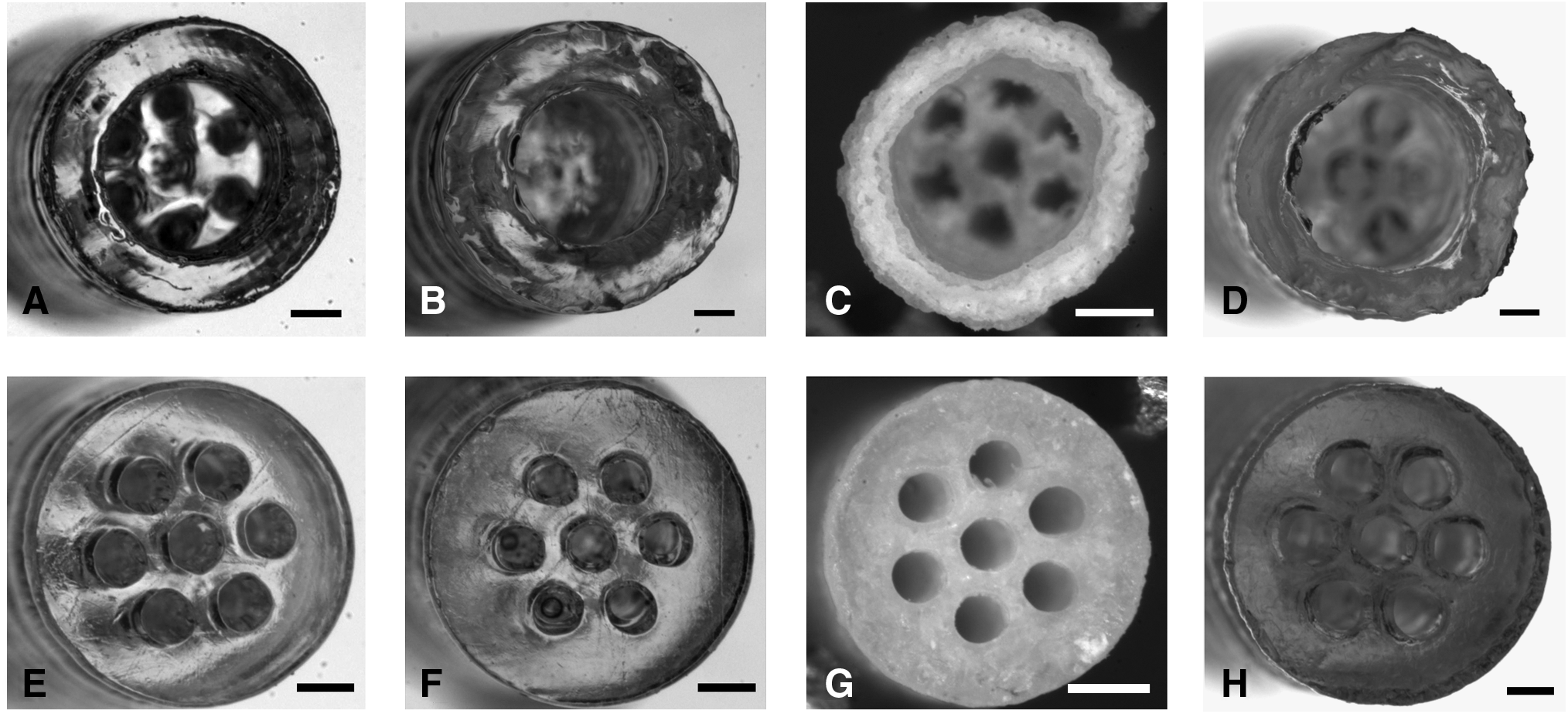
Optical micrographs of the conduits at different stages of the fabrication process. (
Characterization
Weight and dimensional changes
Samples (n = 6) were weighed at different stages of the manufacturing process: immediately after fabrication, after reaching equilibrium in PBS, after lyophilization, after sterilization, and after reconstitution in PBS. The swelling ratio for the samples in equilibrium after fabrication, and after lyophilization was calculated. The swelling ratio is defined as the ratio of the swollen weight to the dry weight (the lyophilized weight was used as the dry weight). Further, the time required for the samples to reach equilibrium when reconstituted was determined by weighing the samples at different time intervals. NGC samples were imaged at different stages of the manufacturing process and different dimensions of the samples were measured. Since the fabricated NGCs' dimensions are different from the CAD, the dimensional swelling factor is expressed as the ratio of the swollen dimension to the dimension immediately after fabrication.
Table 1 shows the weight and dimensions of the samples fabricated with two different concentrations of PEG at the different stages of the manufacturing process. It can be seen that the samples swelled, as both the weight and dimensions of the samples significantly increased when placed in PBS after fabrication. Also, the samples returned to the swollen dimensions when reconstituted in PBS after lyophilization and sterilization. However, the reconstituted samples weighed less than the swollen samples. It should be noted that both the swollen and reconstituted samples were blot dried in a consistent manner using a low-lint tissue wipe (Light-duty tissue wipers; VWR International) before being weighed. For the swollen samples, only the excess water on the surface and inside the lumens is removed when the sample is dried with the wipe. For the reconstituted samples, some of the water trapped in the micropores created during the lyophilization stage (see discussion below in SEM results) may also have been absorbed by the wipe when the sample was blot dried.
Values represent the average ± standard deviation (n = 6).
ID, inside diameter; LD, lumen diameter; OD, outside diameter; PEG-da, poly(ethylene glycol) diacrylate.
Table 2 shows the calculated mass swelling ratio and dimensional swelling factor for samples fabricated with the two different concentrations of PEG. The mass swelling ratio (QS = MS/MD) was calculated using the weight of the swollen samples after fabrication (MS) and the weight of the samples after lyophilization. The calculated mass swelling ratio (8.34 ± 0.35 and 5.82 ± 0.14, for the samples fabricated with 20 and 30 wt.% PEG concentration, respectively) indicates that the samples can uptake approximately eight to six times their own weight in water, depending on the concentration of PEG used to fabricate the samples. By varying the concentration of PEG-da in solution before crosslinking, samples with different properties are obtained. For example, the increase in PEG concentration from 20 to 30 wt.% resulted in a 30% decrease in equilibrium swelling ratio. The change in PEG concentration produces samples with different degrees of crosslinking, where a higher concentration represents a higher crosslinking density, and an increase in crosslinking density represents a decrease in equilibrium swelling ratio. 35
Values represent the average ± standard deviation (n = 6).
DSF, dimensional swelling factor, QS, mass swelling ratio.
Dimensional swelling factor data show that on average the final swollen dimensions of the samples are 13% and 18% larger than the fabricated dimensions for the samples prepared with a 20 and 30 wt.% PEG concentration, respectively.
It should be noted that the dimensions of the NGC design were the smallest permitted by the current SL system and PEG solutions used for the fabrication: 2.94 mm OD, 1.72 mm ID, and with seven 400-μm-diameter lumens. Due to swelling of the material, the dimensions in the final, swollen state were approximately 3.25 mm OD, 2.49 mm ID, and lumen diameter of 516 μm for samples fabricated with a 20 wt.% PEG concentration, and 3.52 mm OD, 2.53 mm ID, and lumen diameter of 546 μm for samples fabricated with a 30 wt.% PEG concentration.
The beam diameter (∼250 μm) used with the current SL system imposes a limitation on the microscale features that can be achieved; as a result, current research is exploring the use of a micro-SL system that will allow for smaller features (x–y resolution of ∼2 μm and z resolution of ∼20 μm). This system will provide for more flexibility in the NGC design such as creating more lumens with smaller diameters, although research is required to extend the fabrication techniques from the current system to the microsystem.
The current SL system can fabricate (before swelling) 400-μm-diameter lumens within a 1.72-mm diameter. The surface area available for cells to attach and grow increases from 5.40 mm2 (in a single lumen with a 1.72-mm inner diameter) to 8.80 mm2, when seven 400-μm-diameter lumens are accommodated within a 1.72-mm diameter. This simple geometric change results in a 63% increase in surface area. However, it should be noted that the available open cross-sectional area is reduced from 2.32 to 0.88 mm2 when changing from the single-lumen design to the multiple lumen design described above, and this reduced cross-sectional area may impede cell movement although further research is required to determine the overall effects of NGC surface area and open cross-sectional area on regeneration. As mentioned above, current research using a micro-SL system shows promise for accommodating at least nineteen 300-μm-diameter lumens that increases surface area to 17.91 mm2 with an available open cross-sectional area of 1.34 mm2.
Figure 3 shows the water absorption curves for NGC samples (n = 6) fabricated with two different concentrations of PEG. The data are presented as the percentage of PBS absorbed at a specific time point relative to the absorbed PBS at 24 h. Figure 3 shows that when placed in PBS for <10 min, the samples absorbed ∼70% of the total PBS that will be taken up. At the first time point considered (7.5 min), the samples fabricated with the 20 wt.% PEG concentration absorbed more PBS (86% ± 2.2%) than the 30 wt.% PEG samples (76.2% ± 1.2%). By 30 min, the samples have approximately reached the equilibrium swollen state as the percentage of PBS absorbed is 97.9% ± 2.7% and 97.5% ± 2.1% for the samples fabricated with 20 and 30 wt.% PEG concentration, respectively.

Swelling curve for NGC samples fabricated with two different poly(ethylene glycol) (PEG) concentrations. The data are expressed as percentage of PBS in the samples at a given time relative to the measured PBS in the samples at 24 h. The average measured value is shown with error bars included that represent ± 1 standard deviation (n = 6).
Scanning electron microscopy
Figures 4–6 show the SEM images of NGC samples. Figure 4 shows cross-sectional images of samples cut into the multilumen region. The schematic in Figure 4A illustrates the plane where the sample was cut. Figure 4B is a low-magnification image showing the complete sample. Figure 4C and D is high-magnification images of the sample showing the internal structure of the material, including a dense skin in the outer portion and a porous, sheet-like inner structure.
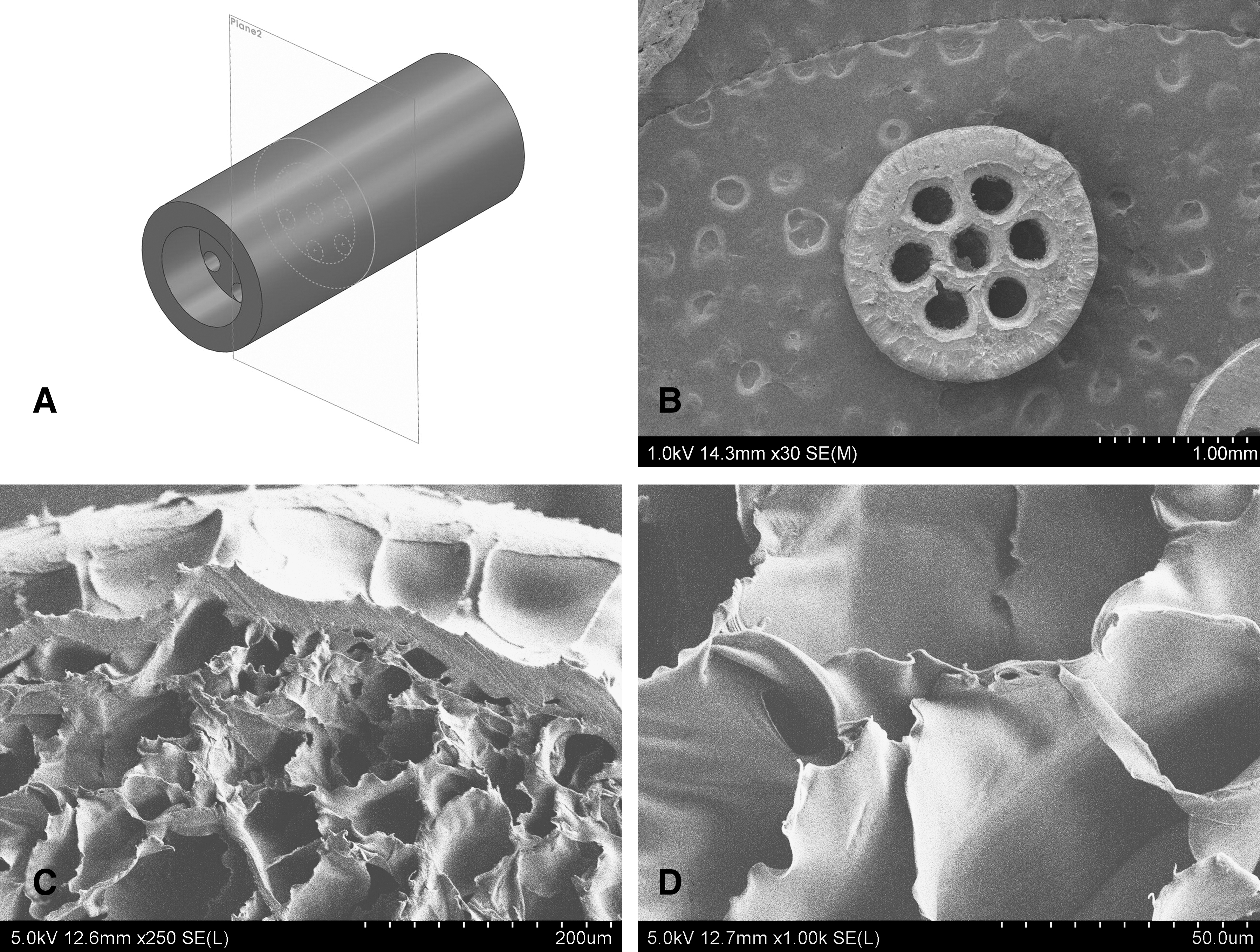
Scanning electron microscopy (SEM) images of NGC samples (cross-sectional cut into the multilumen region). (
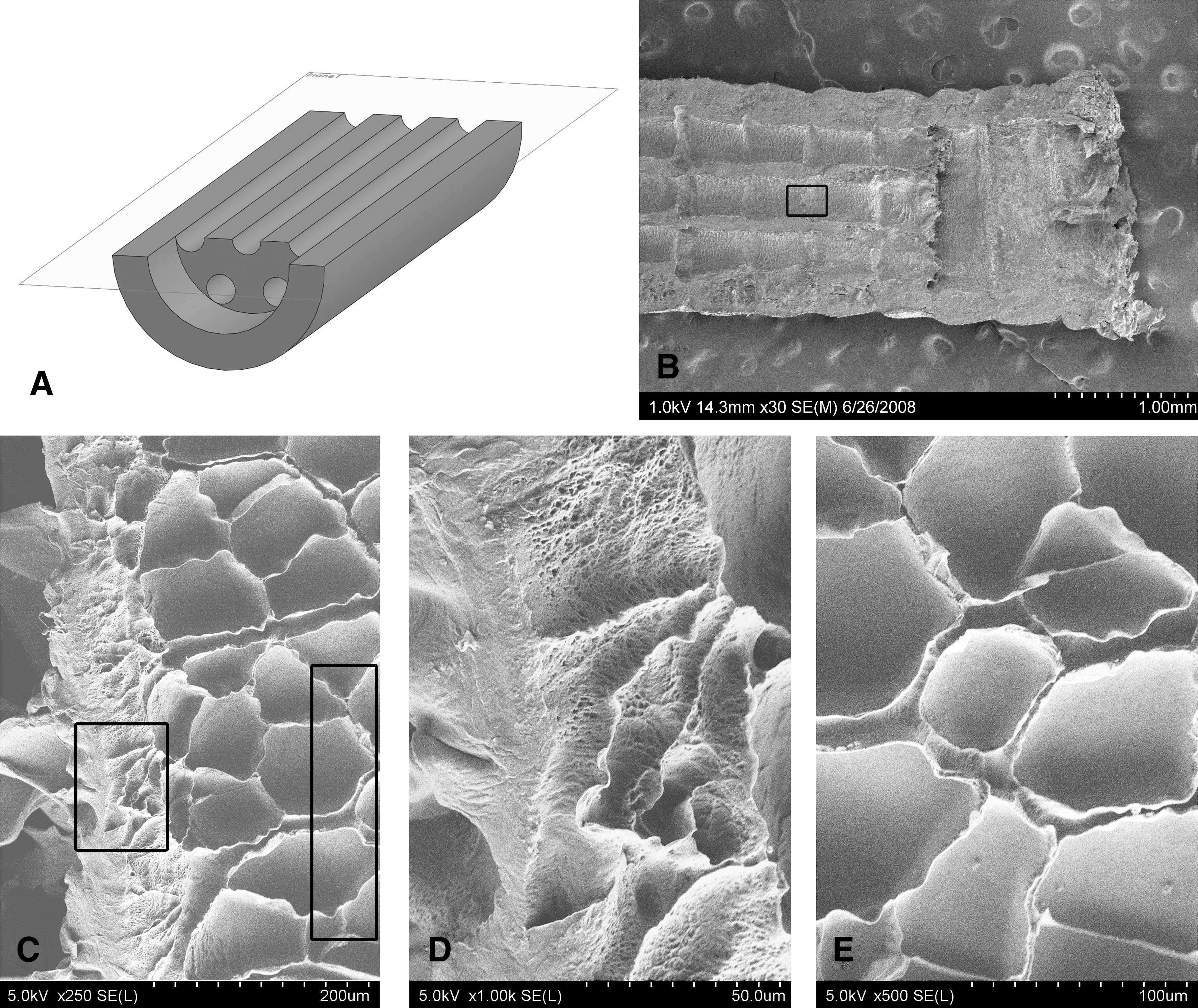
SEM images of NGC samples (cross-sectional longitudinal cut). (
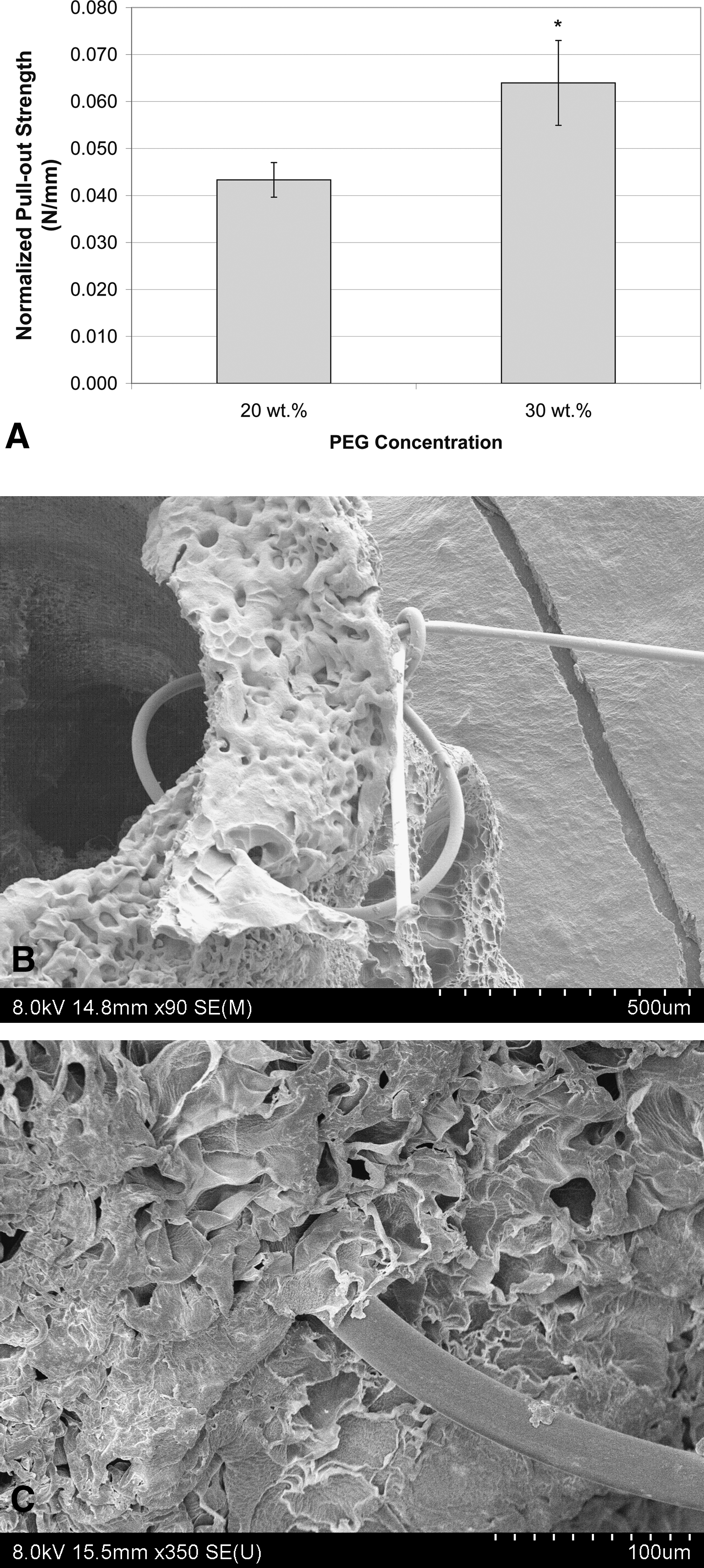
Suture of NGCs. (
Figure 5 shows images of a sample cut longitudinally, where Figure 5A includes a schematic showing the plane where the sample was cut and imaged. Figure 5B is a low-magnification image showing the complete sample in which the five layers of the multilumen section on the left of the image and the three layers of the cap portion (on the right) can be observed. The rectangle in Figure 5B indicates one of the interlayer bonding zones. Figure 5C–E is high-magnification images of the material in zones within the layers and in the interlayer region. Figure 5D shows the sheet-like folding of the material as well a rough pitted surface at the interlayer, whereas Figure 5E shows the material in a layer where a sheet-like structure is also observed but with a smoother surface than the interlayer material.
Suture pullout resistance
Sutures were sewn into the capped portion of the NGCs and pullout tests were performed with the results shown in Figure 6. Figure 6A shows the experimental results of the suture pullout testing on the NGC fabricated with the two different concentrations of PEG (4 ≤n ≤6). The pullout resistance was measured as the force required to pull the suture through the material normalized by the wall thickness of the conduit. The suture pullout resistance significantly (p = 0.0009) increased from 0.043 ± 0.0037 to 0.064 ± 0.0090 N/mm when the PEG concentration was increased from 20 to 30 wt.%. Images in Figure 6B and C show a conduit sutured at the lyophilized state. The material did not tear during suture, and faults or splitting of the material were not observed in these micrographs. The images show the presence of micropores, and a sheet-like microstructure with folds of the material similar to those shown in Figure 5.
The suture pullout data demonstrate that the fabricated conduits can be sutured, and that the conduits fabricated with a higher concentration of PEG are better able to hold a suture. Although future research may be used to improve suture pullout strength, the current design allows the damaged nerve stumps to be inserted into the cap portion of the conduits without tension, thus reducing the suture pullout strength requirements on the PEG-based NGC. If it is determined in future in vivo studies that additional support is necessary, tissue glue can be used in conjunction with sutures to assist with fixation.
Compression testing
NGC samples were tested under a compressive force as implantable NGCs should resist compression from surrounding tissue. Figure 7A shows the testing setup used here. Force versus displacement curves of the four different types of conduits tested under compression are shown in Figure 7B (n = 5). From these curves, the resistance to deformation (in N/mm) of the design, the force to collapse the design, and the force to break the samples were obtained. Results show that the single-lumen design with the dimensions of the cap portion is the most flexible, the multilumen design at the equilibrium swollen state is the most resistant to deformation, and both the single-lumen design with a surface area equivalent to the multilumen design and the multilumen design at the reconstituted swollen state fall in between the other two.
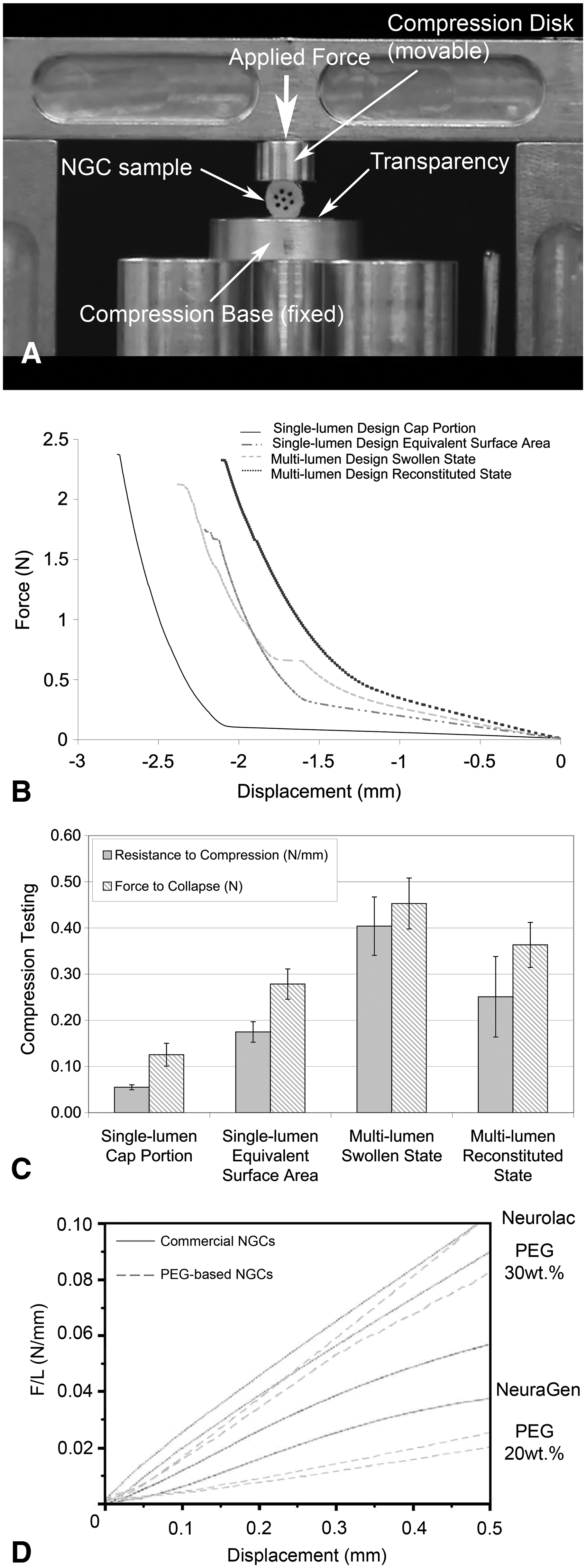
Mechanical testing of NGC samples. (
Comparison of the resistance to deformation and force to collapse for the four different designs was useful in characterizing the fabricated conduits (see Fig. 7C). It was expected that the single-lumen design with the dimensions of the cap portion would be the easiest to deform. As the resistance to deformation depends on the material and the structural design, the single-lumen design with the dimensions of the cap portion has the least amount of material of the four designs. The resistance to deformation for the single-lumen cap portion design was 0.05 ± 0.005 N/mm, and less force (0.13 ± 0.025 N) compared with the other designs was required to collapse it. The multilumen design (with no postprocessing) was better able to resist deformation than the other designs. The resistance to deformation of the multilumen design (with no postprocessing) was 0.40 ± 0.063 N/mm, with more force (0.45 ± 0.055 N) required to collapse the design than the other designs. The reconstituted multilumen design (postprocessed by lyophilization and sterilization) had a resistance to deformation of 0.25 ± 0.087 N/mm, and a force required to collapse the design of 0.36 ± 0.049 N. As the postprocessing of the conduits introduced micropores into the design, the properties of the design changed, resulting in a more flexible, but less strong design. The single-lumen design with a surface area equivalent to the multilumen design (equal amount of material) had a resistance to deformation of 0.17 ± 0.022 N/mm and the force required to collapse the design was 0.28 ± 0.033 N, which are considerably smaller than the multilumen designs both with and without postprocessing (for dimensions of the designs, see section Characterization–Compression Testing).
The force to failure results indicate that the point of failure is determined by the material properties and not the structural design. There is no statistically significant difference in the force required to completely break the four different conduits (2.07 ± 0.41 N). Also, it can be seen in Figure 7B that once the structural design of the conduit has been collapsed, the deformation experienced is that of the material as the slope of the curves is the same.
Compression data for commercially available NGCs available in the literature indicate that the deflection force per unit length increases linearly with displacement (similar to the initial portion of the curves in Fig. 7B). 44 Figure 7D shows the deflection force per unit length as a function of displacement data for commercially available NGCs as well as for the PEG conduits fabricated in this study. It can be seen that the conduits fabricated with a PEG concentration of 30 wt.% have compressive resistance comparable to commercially available NGCs. The slope of the deflection force per unit length as a function of displacement curve for NeuraGen® collagen conduits is ∼0.11 and 0.2 N for the Neurolac® conduits made with poly(DL-lactide-co-caprolactone). 44 The slope of the curve for deflection force per unit length as a function of displacement for the multilumen conduits in this study is ∼0.04 and 0.2 N for the 20 and 30 wt.%, respectively. This slope can be normalized to calculate a compressive modulus, indicating that using higher concentrations of PEG result in samples with higher elastic moduli.
Coefficient of friction
Experimental results of a simple experiment to determine the static coefficient of friction of NGCs at the equilibrium swollen state (non-post-processed) and reconstituted to equilibrium after lyophilization and sterilization (post-processed) showed that the angle at which the conduits started to slide was ∼30° for non-post-processed conduits and ∼48° for postprocessed conduits. The calculated coefficient of friction of the conduits on glass was 1.10 and 0.56 for conduits with and without postprocessing, respectively. Postprocessing of the conduits resulted in a rough surface topography, and as a consequence, less slippery conduits. Therefore, the postprocessed conduits at the swollen state are easier to handle, which is a desirable characteristic of the ideal NGC.
Conclusions
The fabrication of a 3D, multilumen NGC design using the additive manufacturing technology of SL and a water-based solution with photocrosslinkable high-molecular-weight PEG was demonstrated. The design of the NGC has two important characteristics: a capped portion at each end that allows effective suturing of the proximal and distal stumps of the damaged nerve to the NGC, and a multilumen middle portion that provides a greater surface area for support cells and sprouting axons. A complete manufacturing process for implantable, off-the-shelf NGCs was developed and consisted of four stages: (1) photocrosslinking using SL, which permits a rapid fabrication strategy for complex 3D scaffolds; (2) swelling to equilibrium, to allow the scaffold to reach the final dimensions while removing unreacted photopolymer; (3) lyophilization, which preserves the scaffold, making it an off-the-shelf product with improved suturability; and (4) sterilization with hydrogen peroxide, to be able to implant in vivo. Optical and scanning electron microscope characterization of the conduits showed that the conduits had a rough topography in the free-surface and that a microporous, sheet-like microstructure of the material was created by the lyophilization process.
The dimensions of the NGC design were the smallest permitted by the current SL system and PEG solutions used for the fabrication: 2.94 mm OD, 1.72 mm ID, and with seven 400-μm diameter lumens. Due to swelling of the material, the dimensions in the final, swollen state were ∼3.25 mm OD, 2.49 mm ID, and lumen diameter of 516 μm for samples fabricated with a 20 wt.% PEG concentration, and 3.52 mm OD, 2.53 mm ID, and lumen diameter of 546 μm for samples fabricated with a 30 wt.% PEG concentration. Collectively, the final swollen dimensions were ∼13% larger in the samples fabricated with a 20 wt.% PEG concentration, and 18% larger for the 30 wt.% samples, compared to the fabricated dimensions. The degree of swelling and dimensional swelling factors for the two PEG solutions were measured and confirmed that the final dimensions of the conduits were significantly larger than the original dimensions after fabrication, and that the samples return easily and rapidly to a swollen state when placed in an aqueous solution, maintaining their original overall structure.
Further characterization showed that the postprocessed conduits at the swollen state were less slippery and therefore easier to handle during implantation, which represents a desirable characteristic of the ideal NGC and allowed for improved suturing of the scaffolds. Suture pullout resistance experiments showed that the fabricated NGCs can be sutured, and conduits fabricated with a higher concentration of PEG were better able to hold a suture. As implantable NGCs should resist compression from surrounding tissue, it was demonstrated that a multilumen design (with and without postprocessing) was better able to resist compression than a single-lumen design with an equivalent surface area. It was also shown that conduits fabricated with a 30 wt.% PEG concentration have compressive resistance comparable to that of commercially available NGCs.
In summary, SL shows promise for creating complex 3D tissue-engineered scaffolds in a rapid, efficient manner. Advantage offered by SL include the ability to easily alter the scaffold design by simply altering the CAD, allowing flexibility in the system, relatively simple scalability of the manufacturing process, and access to individual layers during fabrication enabling control over 3D material placement and structure creation. By expanding the techniques described in this work to micro-SL, considerable improvements to the NGC design can be accomplished, and research is ongoing in multimaterial fabrication using micro-SL to ultimately produce an implantable, multimaterial, bioactive NGC with tailored, spatially controlled bioactivity and degradation characteristics.
Footnotes
Acknowledgments
This work was funded primarily by the National Science Foundation under Grant No. CBET-0730750 and performed at the University of Texas at El Paso (UTEP) within the W.M. Keck Center for 3D Innovation (Keck Center). Funding was also provided, in part, through the Chihuahua Government (scholarship to K.A.) and the Mr. and Mrs. MacIntosh Murchison Chair I Endowment in Engineering (R.B.W). The authors are grateful for the assistance of Frank Medina, Edgar Lucero, and David Espalin of the Keck Center on various aspects of the project. The UHR Hitachi 4800 FE-SEM in the Metallurgical and Materials Engineering Department used in this research was purchased through a grant from the National Science Foundation (NSF-DMR-0521650). Drs. Gregory Evans and Thomas Vetter from the Aesthetic and Plastic Surgery Institute at the University of California Irvine sutured the samples used in the suture pullout tests and their efforts are appreciated. Any opinions, findings, and conclusions or recommendations expressed in this material are those of the authors and do not necessarily reflect the views of the National Science Foundation or any other individual or funding agency.
Disclosure Statement
No competing financial interests exist.