
Abstract
A novel squeeze pressure bioreactor for noncontact hydrodynamic stimulation of cartilage is described. The bioreactor is based on a small piston that moves up and down, perpendicular to a tissue construct, in a fluid-filled chamber. Fluid displaced by the piston generates a pressure wave and shear stress as it moves across the sample, simulating the dynamic environment of a mobile joint. The fluid dynamics inside the squeeze pressure bioreactor was modeled using analytical and computational methods to simulate the mechanical stimuli imposed on a construct. In particular, the pressure, velocity field, and wall shear stress generated on the surface of the construct were analyzed using the theory of hydrodynamic lubrication, which describes the flow of an incompressible fluid between two surfaces in relative motion. Both the models and in-situ pressure measurements in the bioreactor demonstrate that controlled cyclic stresses of up to 10 kPa can be applied to tissue constructs. Initial tests on three-dimensional scaffolds seeded with chondrocytes show that glycosaminoglycan production is increased with regard to controls after 24 and 48 h of cyclic noncontact stimulation in the bioreactor.
Introduction
Thanks to numerous studies, pioneered by Mow and coworkers, the loading environment of diarthrodial joints is generally well understood. Under normal circumstances, the loading duration of diarthrodial joints is generally cyclical and/or intermittent,15,16 even for seemingly static activities such as standing or sitting, which involve back and forth shifting of the body weight to relieve loading of the joints. The normal loading environment of chondrocytes involves intermittent cyclical fluid pressurization, during which fluid in the synovial sac flows across the tissue.17,18 Under these conditions, chondrocytes are able to balance their synthetic and catabolic activities to maintain the integrity of articular cartilage in vivo.19,20
In this work, an innovative stimulation chamber inspired by the synovial environment of mobile joints is described and modeled. The squeeze pressure bioreactor (SQPR) chamber is designed to impose a cyclic hydrodynamic pressure on cell cultures, constructs, or tissues slices. One of the most important features of the SQPR chamber is the ability to generate a well-controlled dynamic squeeze pressure without requiring any contact with the samples, thus simulating the load-bearing and lubrication function of natural cartilage in mobile joints such as the knee. Validation tests in the bioreactor were carried out by submitting chondrocytes seeded on PGA (polyglycolic acid) scaffolds to a pressure of 1–10 kPa at a frequency of 1 Hz, the typical step frequency during walking. Both cell viability and matrix production were assessed after 24 and 48 h of stimulation in the SQPR.
Materials and Methods
Bioreactor design
As illustrated in Figure 1A, the bioreactor is made up of three main parts: a freely moving piston, a fluid filled chamber, and a base that supports the tissue construct. The piston, A, oscillates vertically in the fluid, approaching and receding from the base, B, without touching the construct. As the piston approaches the base, the displaced fluid generates a shear stress and hydrodynamic pressure gradient across the base, while forming what is known as a “squeeze” film in the meatus (zone between construct and piston). In fact, the introduction of a fluid film between two moving surfaces provides a lubricating effect that substantially reduces the coefficient of friction between them.

The SPQR was designed to apply a contactless hydrodynamic pressure on tissue constructs over long periods of time (24 h or more) using the squeeze film principle. Additional requirements were that it be easy to use, sterilize, assemble, disassemble, compact, sturdy, transparent, compatible with standard culture inserts and scaffolds, and allow gas exchange and medium sampling. All components were machined at the University of Pisa workshop. The piston consists of a 6 mm diameter stainless steel shaft and a 14 mm diameter Derlin head. The shaft was machined with H7 tolerance to obtain perfectly aligned motion parallel to the chamber walls. A small threaded hole was drilled on the top of the shaft for coupling to the linear motor (model 809100; Crouzet), and a groove was cut to allow insertion of a seeger ring for use as an excursion limit. The Plexiglas SQPR chamber has an internal diameter of 18 mm. Two 4 mm holes on the top of the chamber, compatible with syringe filters and Luer-lock connectors, allow filling and sample collection during experiments, as well as passage of oxygen. The Delrin base of the SPQR bioreactor has a diameter of 18 mm and is screwed into an aluminum plate that supports the walls of the chamber. The bioreactor components and further construction details are reported in Figure 1B.
Figure 1C shows the assembled system with the outer frame where the linear stepper motor is fixed and in which the chamber sits during stimulation experiments. The bottom plate of the frame has a lip to align and hold the chamber and two L-shaped clamps to fasten the bioreactor in place. The motor is attached to the top of the frame and is protected from humidity by a case through which the motor cable is inserted via a water-proof connector. We also designed a dedicated electronic system interfaced to a PC to allow frequency and velocity control of the piston's motion. The bioreactor was assembled under a sterile hood and then moved to a cell-culture incubator for the stimulation experiments.
Analytical model
The fluid dynamics inside the bioreactor can be described using the fluid film lubrication theory, originally proposed by Reynolds in 1886. 21 Reynold's equation describes the generation of hydrodynamic pressure between two surfaces separated by a thin film of fluid using three terms: wedge, stretch, and squeeze, according to the type of motion between two surfaces. Such films are usually sufficiently thin that viscous forces are large in comparison with inertial forces, so that the latter may be neglected. The terms wedge and stretch refer to lateral or sliding motion between two rigid surfaces, whereas the term squeeze refers to perpendicular motion, as in our case.
As described in Appendix 1, for a given piston velocity V, we can obtain the pressure field, p(r) (equation 1), and the velocity field, v(r,z) (equation 2), in a fluid of viscosity μ.
where h is the distance between the two surfaces, or meatus height. The other terms are referred to in Figure 1A.
The wall shear stress on the bottom plate (τw at z=0) can then be obtained from Newton's law, using equation 2:
Finite element model
The analytical model assumes an unconfined system in which one of the plates is an infinite plane. Therefore, to simulate the fluid dynamics inside a confined bioreactor chamber, a finite element method (FEM) model of the system was developed using COMSOL Multiphysics (COSMOL AB version 3.4). The Incompressible Navier–Stokes application mode for Newtonian flow was used to calculate the velocity field v, the pressure distribution p, and the wall shear stress τw on the bottom plate. A two-dimensional axial symmetric system representing the bioreactor chamber with confined walls and fixed inner volume was analyzed in stationary conditions at different minimum meatus heights (h=150, 200, 250, and 300 μm) and for different construct radii. The complete model is shown in Figure 2. The fluid viscosity used was 4.77×10⁻³ Pa·s, corresponding to that of the high viscosity (HV) medium used in the cell-culture experiments. Boundary conditions were defined as in Table 1. Finally, the piston velocity V was set to -0.0116 m/s (the maximum motor speed) in the approach phase and 0.002 m/s in retraction; the retraction velocity was determined experimentally to obtain a frequency of about 1 Hz for a total excursion of 1 mm. Note that a lower retraction velocity is also necessary to avoid the generation of excess negative pressures which could cause turbulence and raise the cell-seeded construct from the base of the bioreactor. A mapped mesh of 594 elements was obtained by fixing the number of edge elements on boundaries 1, 2, 3, and 9, respectively, to 9, 42, 12, and 4 linearly distributed elements. All models were solved with the UMFPACK direct solver available in COMSOL on a Macbook 5.1 (Intel Core 2 Duo, 2 GHz CPU) running Mac OS X.

SQPR FEM model scheme. Numbers in the scheme indicate the boundary numbers specified in the model and listed in Table 1. The modeled region is shaded light gray. FEM, finite element method.
The numbers refer to those in Figure 2.
Pressure measurement
A pressure transducer (Vegabar 14, VEGA Grieshaber KG, dynamic range: −10 to 10 kPa, resolution: 20 Pa) was used to validate the results obtained from the models. The pressure transducer was placed under the bioreactor chamber by drilling holes in the sample holder and base (shown with dotted lines in Fig. 1B). In this way, the 6 mm diameter sensor element is directly in contact with the pressurized fluid. The measuring system was also modeled using COMSOL to verify that the overpressure at the bioreactor base also affects the sensing element of the pressure transducer. Tests were performed with the same cyclic stimulation, the same HV medium, and at several minimum meatus heights, as used in the models.
Cell culture
Chondrocyte isolation and culture
Bovine adult chondrocytes were isolated from the ankle of a 2-year-old animal as described in Crawford and Dickinson. 22 The basic culture medium used for all the experiments was Dulbecco's modified Eagle's medium (DMEM) (Sigma-Aldrich) containing 10% (v/v) fetal calf serum (Sigma-Aldrich), 1% (v/v) antibiotic antimycotic solution (10,000 units/mL penicillin, 10 mg=mL streptomycin; Sigma-Aldrich), 10 mmol HEPES, nonessential amino acids (0.1 mmol; Sigma-Aldrich), and 2 mmol L-glutamine and referred to as complete DMEM. Immediately after isolation, a cell count and viability assessment was performed using Trypan Blue (0.4% w/v, Sigma-Aldrich). 23 The isolated cells were seeded in tissue-culture plates and cultivated as described in Oliveira et al. 24 After the second passage, the cells were trypsinized (Trypsin, 0.25% v/v, Sigma-Aldrich) and prepared for seeding onto the three-dimensional scaffolds. Scaffolds (100% PGA felt, 1 mm×5 mm diameter, 70 mg/cc, manufactured by Concordia, and purchased from Cellon) were seeded with a density of 2.5×10⁶ cells/scaffold and cultivated as described in Oliveira et al. 24 After 5 days of culture, the constructs were ready for the bioreactor and control experiments.
SQPR experimental protocol
Preliminary tests were carried out to verify whether oscillation of the piston affected the position of the construct during stimulation and to calibrate the starting position of the system with regard to the scaffold. The piston was brought down slowly to just touch the scaffold while observing the construct with a video camera. It was then raised by 200 μm. This position was considered as the “zero” starting position for the experiments.
The purpose of the cell culture experiments was to assess the performance of the SQPR in stimulating chondrocytes with a cyclic squeeze pressure, thus mimicking the dynamic in vivo environment of articular cartilage. To mimic the viscosity of the fluid environment in the synovial sac, all experiments were performed using HV medium. The HV medium consists of complete DMEM with 5% w/v Dextran 500 (Sigma-Aldrich), 1% v/v 50 mg/mL ascorbic acid, and 0.1% v/v 5 mg/mL insulin (Sigma-Aldrich). The measured kinematic viscosity and the density of the HV medium were, respectively, 4.64×10⁻⁶ m2/s and 1.029.103 kg/m3 (Cannon–Fenske viscosimeter; Franceschi Sas).
Cell viability was evaluated using the Alamar Blue assay, 25 whereas the glycosaminoglycan (GAG) content was determined using the method described by Farndale et al. 26 Briefly, samples of culture medium were mixed 50:50 with 0.5 mg/mL papain (in 200 mM phosphate buffer containing 1 mM EDTA and 0.96 mg/mL acetyl cysteine, all from Sigma-Aldrich) for 2 h at 60°C; and GAG levels were determined using dimethyl-methylene blue absorbance. The increase in GAG content in the medium is directly linked to matrix production in immature constructs, as they do not possess sufficient ECM to incorporate newly synthesized GAGs, and is an indicator of chondrocyte activity and function.12–14
Before each experiment, the bioreactor was sterilized by soaking all the components in 70% ethanol for 30 min. To obtain a baseline value of viability, each cell-seeded construct was first assayed using Alamar blue at time t=0. Then, one scaffold was placed at the center of the bioreactor base, and an identical sample was left in a 12-well plate in 4 mL of HV medium as a control. The SQPR chamber was closed, and 4 mL of HV medium was gently pipetted into the chamber through the lateral holes using a sterile Pasteur pipette. Two sterile syringe filters were placed in the lateral holes, to prevent infection and medium evaporation. Finally, the SQPR chamber was put in the frame, linked to the motor shaft, and the whole system was placed in a 37°C, 5% carbon dioxide incubator, together with the control. We imposed a cyclic stimulation at a frequency of 1 Hz with h=200 μm, with approach and retraction velocities of 0.0116 m/s and 0.002 m/s, respectively, for a period of 48 h. At 24 h, 0.2 mL of medium was aspirated from the bioreactor and from the control samples to evaluate GAG production. Immediately after the end of the experiment, a second Alamar Blue assay was performed to check cell viability; and media samples were set aside for analysis of GAG content. In some cases, viability was also evaluated at 24 h by interrupting the stimulation halfway through the experiment.
Data analysis
A total of six scaffolds were used; three for the static controls and three for the hydrodynamic experiments using the same batch of cells. Each data point represents the mean and standard deviation of viability and GAG content in the medium from three scaffolds. Statistical analysis of cell viability and GAG concentration was performed using nonparametric Kruskal–Wallis ANOVA. Significance was set at p<0.05.
Results
Models and pressure measurements
In this work, we simulated the fluid dynamics inside the SQPR using both an analytical and FEM model to evaluate the pressures and the shear stresses generated in the system. To find a good compromise between high pressure and moderate shear stress on the base, 27 a parametric analysis was performed using different minimum meatus heights, h. To this end, the analytical model was first solved by implementation of equations 1 and 3 in MATLAB (The MathWorks, Inc.) for different values of h for fixed approach (v=−0.0116 m/s) and retraction velocities (v=0.002 m/s). The results showed that for values of h<200 μm, the wall shear stress reaches values of greater than 50 Pa, which may be harmful to cells. 28 We then ran the two-dimensional model with the complete geometry of the bioreactor, including inertial terms and gravitational forces (i.e., the fluid density was set at 1029 kg/m3). Figure 3A shows the pressure profile across the base B obtained at h=200 μm using the analytical and FEM models. In the approaching phase, the pressure calculated from FEM model is about 7% higher than the analytical model (corresponding to 76 Pa at the center of the base in the approaching phase) and is due to the over-pressure determined by the wall of the bioreactor as well as to inertial forces. These two factors were neglected in the analytical model. The values of wall shear stress obtained from the two models differ by a maximum of about 10% at the edge of the piston (about 3.7 Pa) as shown in Figure 3B. In this case, the difference could be due to the edge effect that was also not considered in the analytical system. In the FEM models, neither the pressure nor the shear stress in the central part of the bioreactor base was affected by the radius of the construct. Finally, the FEM results at different minimum meatus heights were compared with the experimental pressure measurements. For each test, the output signals were recorded for 1 min and the mean value of the maximum pressure measured over 60 cycles. Since the pressure sensor was placed at the center of the construct, and the sensor head is 3 mm in radius, it measures a sort of integrated pressure value over this radius. The sensor output signal for a minimum height of 200 μm and a total excursion of 1 mm is shown in Figure 4A, whereas the values of average pressure for various minimum meatus heights are shown in Figure 4B.
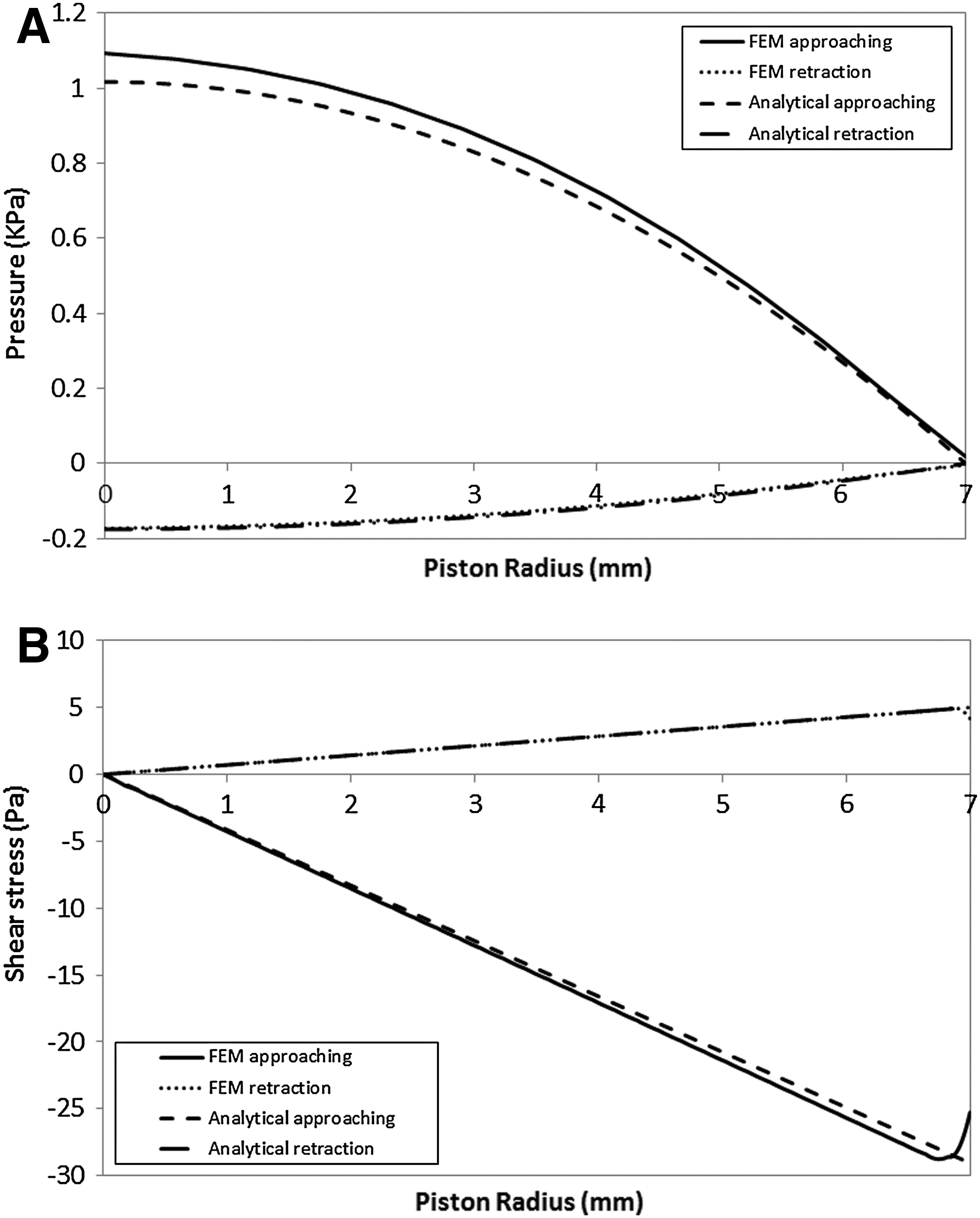
Comparison between FEM and analytical models.

Cell culture
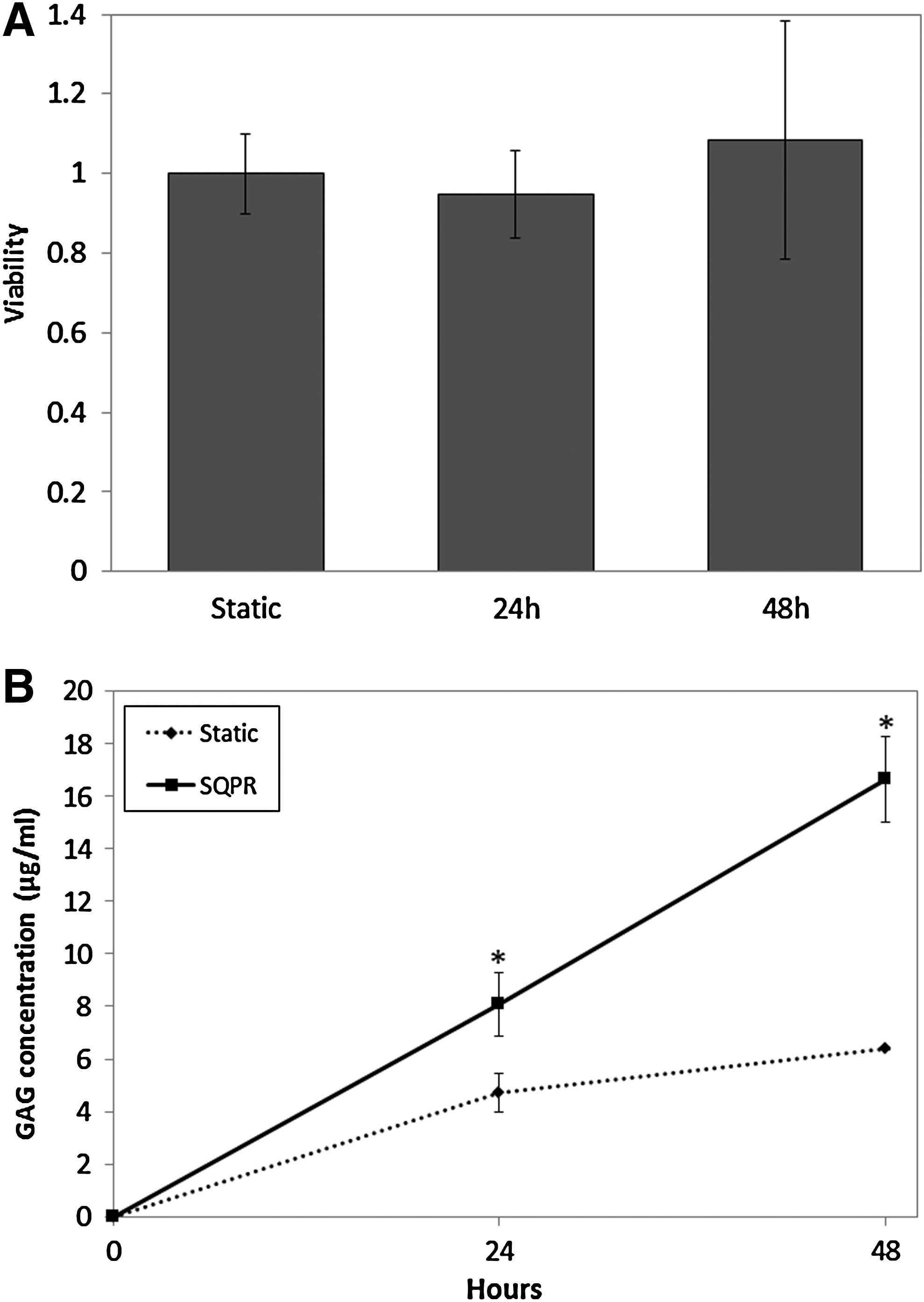
Figure 5A shows that the viability of chondrocytes seeded on the PGA scaffolds and subject to cyclic squeeze pressure over 48 h was comparable with that of unstimulated controls, showing that the SQPR environment does not compromise mitochondrial activity. On the other hand, the concentration of sulfated GAG was higher in the stimulated samples (Fig. 5B). In particular, after 48 h of cyclic noncontact stimulation, the concentration of GAG was nearly thrice higher than the controls. Moreover, the rate of increase was higher in the SQPR, indicating that the cells were constantly stimulated to produce GAG in the bioreactor; whereas in control conditions, the rate of production decreases after 24 h.
Discussion
The main purpose of this work was to demonstrate that the SQPR system can apply a cyclical contactless hydrodynamic pressure to tissue-engineered constructs, thus allowing mechanical stimulation without damaging cells. This is particularly important in the initial phases of regeneration in which the cells have yet to express matrix proteins and cells at the edges of the construct may be sensitive to large contact forces. In fact, the constructs were used 5 days after seeding the PGA scaffolds with chondrocytes. Constructs of this maturity and scaffold type cannot be used with conventional compressive loading bioreactors due to the relative fragility of the PGA fleece.
Although physiological loads at articular surfaces are usually higher than the stimuli applied by our system, the hydrodynamic environment generated in the bioreactor chamber recapitulates many of the features of the joint environment. In particular, the SQPR mimics the formation of a squeeze film due to the motion of joints and the subsequent generation of a velocity field giving rise to a pressure gradient and shear stress.
Analytical and FEM models of the hydrodynamic environment within the meatus were developed to determine the working window of the system. The correspondence between the two models was verified, and the FEM results were also validated through experimental pressure measurements. The SQPR system can generate a squeeze pressure between 1 and 15 kPa with various frequencies; corresponding wall shear stresses, generated by the flow of fluid in and out of the meatus, are of the order of 0–25 Pa. As shown in equations 1 and 3, the pressure and shear stress applied depend on the minimum meatus height and velocity. High pressures also mean high wall shear stress. The working range of the system was chosen as the best compromise between tolerable, nondamaging, 28 shear stress on the surface of the scaffold, and the specifications of the motor. Higher pressures and stresses can be generated by increasing the approach speed and decreasing the minimum meatus height, but this places stringent requirements on the performance of the stepper motor in terms of positioning accuracy and acceleration.
The performance of the SQPR was tested on chondrocyte-seeded scaffolds by submitting the constructs to a controlled noncontact cyclic squeeze pressure for up to 48 h. Since the typical doubling time of these cells is 72 h, we can assume that cell proliferation was minimal and that cell vitality in the stimulated scaffolds did not change with regard to static controls over the first 24 h. In addition, we observed that the 24 h long stimulation resulted in a 2-fold increase in GAG production, whereas the longer 48 h stimulation gives rise to an almost 3-fold increase with regard to static controls. In fact, the GAG production curves in control conditions tend to decrease after 24 h, suggesting that these constructs gradually lose the ability to produce ECM. The scaffolds in the bioreactor do not show this decrease in production, indicating that the contact-less pressure induces the constructs to maintain increased matrix synthesis instead of lapsing into a quiescent phase.
Footnotes
Analytical Derivation of Equations 2,3,and 4
Starting from the most general form of Reynolds equation, as originally proposed in 1886, we can use the Navier–Stokes equations to simplify the lubrication model when inertial effects and other external forces (e.g., gravity) are negligible. The velocity distribution in the squeeze film between a flat, round plate and a smooth base can be derived as demonstrated below.
In its most general form, the Reynolds equation can be written as follows:
where x, y are mutually perpendicular coordinates within the fluid, p is the local pressure within the film, ρ and μ are the density and absolute viscosity of the lubricant, respectively, h is the film thickness, and U1 and U2 are the velocities of sliding (lateral movement) of the upper and lower surfaces, respectively.
The physical significance of this equation is that the generation of hydrodynamic pressure within the film depends on the three terms on the right hand side of the equation, respectively, the wedge, stretch, and squeeze contributions to load support. In our case, both U 1 and U2 are zero; since there is no sliding motion, so only the term squeeze is applied.
In the analytical model, we consider the instant at which the piston is at its closest to the base, such that the height of the meatus is at its minimum. Given that the minimum meatus height, h, is small with regard to the dimensions of the two surfaces, the pressure in the vertical direction (Fig. 1A, main text) can be considered constant. In Cartesian coordinates, the simplified Reynolds equation used to represent the system can then be written as follows:
where p is the local pressure within the film, μ is the viscosity of the fluid, h is the film thickness, and V the relative velocity
Assuming the meatus between x=0 and x=a, this expression can be integrated twice with the boundary condition p|(x=a)=pa and p|(x=a)=pa, to obtain the pressure field p(x) in Cartesian coordinates:
As shown in Appendix Figure A1, cylindrical coordinates (r, θ, z) and axial symmetry can also be used to describe the system. In this way, further simplifications can be made to find the pressure and velocity distribution in the meatus directly in cylindrical coordinates. We consider a small element dVol within the film of radius r and height h, in which surface A of radius R approaches toward or retracts from the fixed infinite surface B. The pressure and viscous forces acting on the surfaces of the element are shown in Figure 2A (main text). Starting from the equilibrium of all the radial forces acting on dVol and applying the continuity equation to the squeezing process (with boundary conditions v=0 at z=0 and z=h (no slip), p|(r=R)=pa, an initial pressure, corresponding to 0 in our case). From symmetry conditions, the absence of viscous forces acting on faces drdz can be assumed. Considering stationary conditions, the equilibrium of the radial forces acting on the small element dVol within the film of radius r and height h is
Assuming Newtonian viscosity
where vr is the local velocity of the fluid in the r-direction. This expression can be integrated twice:
Considering the boundary conditions vr=0 at z=0 and z=h, we can obtain the constants c1(r,θ) and c2(r,θ):
So, the expression (5) can be written as
The term dp/dr can be obtained by applying the continuity equation to the squeezing process:
Rearranging equation 8:
This equation can be integrated by using the boundary condition p(r=R)=pa, obtaining
Replacing equation 9 in equation 7, the velocity distribution is obtained:
Assuming R=a, equation 2 is similar to equation 12 but two-fold higher as a result of the different coordinate system chosen. This validates the analytical derivation of the pressure and velocity distribution in a squeeze film in cylindrical coordinates using the equilibrium of radial forces.
The work was performed at the University of Pisa (bioreactor development) and University of Sheffield (cell culture).