
Abstract
Computed tomography (CT) represents a truly three-dimensional (3D) imaging technique that can provide high-resolution images on the cellular level. Thus, one approach to detect single cells is X-ray absorption-based CT, where cells are labeled with a dense, opaque material providing the required contrast for CT imaging. Within the present work, a novel cell-labeling method has been developed showing the feasibility of labeling fixed cells with iron oxide (FeO) particles for subsequent CT imaging and quantitative morphometry. A biotin–streptavidin detection system was exploited to bind FeO particles to its target endothelial cells. The binding of the particles was predominantly close to the cell centers on 2D surfaces as shown by light microscopy, scanning electron microscopy, and CT. When cells were cultured on porous, 3D polyurethane surfaces, significantly more FeO particles were detected compared with surfaces without cells and FeO particle labeling using CT. Here, we report on the implementation and evaluation of a novel cell detection method based on high-resolution CT. This system has potential in cell tracking for 3D in vitro imaging in the future.
Introduction
Compared with existing 2D imaging methods, the development of a new X-ray absorbing cell-labeling method for high-resolution CT would allow more detailed information beyond 2D tissue surfaces. Though, imaging of low X-ray absorbing structures such as cells presents one of the major problems of absorption-based CT imaging. On this account, CT imaging so far has mainly been restricted to hard tissues, which yield high X-ray absorption providing image contrast. Alternatively, edge enhancement or phase contrast present to the high coherence of third-generation SR sources has been exploited to image single cells within surrounding tissue, such as chondrocytes within extracellular matrix of articular cartilage. 13 However, increasing edge enhancement comes along with decreasing contrast within the sample structures, impeding reliable quantitative morphometry. Although more advanced methods for phase-contrast imaging were proposed14–22 and used, they rest upon elaborate experimental setups and conditions or need semi-empirical input parameters to provide quantitative data.
For these reasons, the present work describes the extension of an existing cell-labeling method to high-resolution absorption-based CT imaging. The method is based on the binding of a specific antibody of interest in connection with biotin to a streptavidin-iron oxide (FeO) particle system (Fig. 1), primarily used for magnetic cell separations. 23 Cells that are strongly bound to FeO particles are extracted using magnetic fields. The basis of the antibody system resides in the exceptionally high-affinity constant between streptavidin and biotin and the possibility to theoretically target any extracellular or membrane-bound antigen. In this way, FeO particles are bound to the desired target, for example, a specific cell type, and enable its localization in three dimensions. The attenuation coefficients of bone (54.74 [1/cm]) and FeO (769.3 [1/cm]) infer that FeO should be distinguishable from hard tissue. Therefore, this method might be advantageous in detecting cells in bone tissue-engineered constructs as well as in soft tissue-engineered constructs (5.70 [1/cm]). Therefore, with an ∼180×higher absorption of FeO compared with the surrounding soft tissue or cells, the location and 3D distribution of these FeO particles can be visualized by high-resolution CT. Because vascularization of tissue-engineered constructs either before or after implantation in vivo is considered one of the primary reasons for implant failure in vivo, we chose microvascular endothelial cells as a labeling target. If functional vessels were engineered in vitro, this method should theoretically allow the localization of cells in vessels (especially functional ones) and show their distribution in 3D. The labeling method theoretically can be expanded to all sorts of cell types or extracellular matrix components by interchanging the primary antibody. The feasibility of the system was first investigated in two dimensions on polystyrene (PS) surfaces. The results were then translated into 3D by the labeling of fixed endothelial cells grown on highly porous polyurethane (PU) scaffolds. The aim of this article was to establish and test a novel cell-labeling method for high-resolution CT.
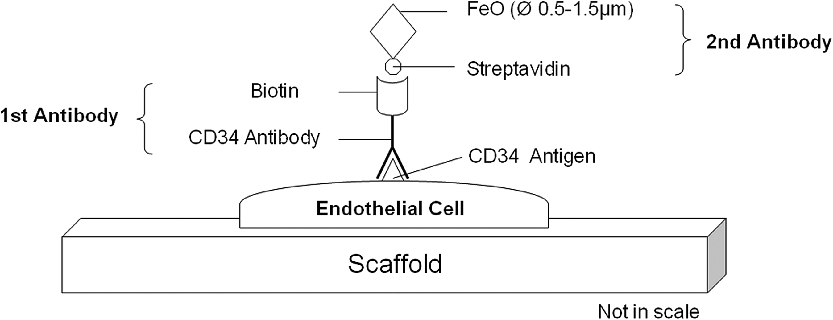
CD34–Biotin–Streptavidin–FeO-based cell-labeling method. The biotinylated primary antibody is coupled to an antigen on the outer cell surface. This step is followed by the binding of a streptavidin–FeO complex for further X-ray CT imaging. FeO, iron oxide; CT, computed tomography.
Materials and Methods
Scaffold characterization
μCT was used to characterize scaffold morphometrical properties of used PU scaffolds. 3D visualizations of five 5-mm disk-shaped pieces of plain PU (Granufoam™; KCI Inc., Rümlang, Switzerland) were contrast stained in 0.04% osmium tetroxide (OsO4; Fluka, Buchs, Switzerland) in 0.1 M Na-cacodylate buffer (Sigma-Aldrich, Buchs, Switzerland; pH 7.4) for 2 days for ideal CT imaging and dried at room temperature in a desiccator for 3 days. Scaffolds were measured with a μCT system (μCT 40; Scanco Medical, Brüttisellen, Switzerland). An isotropic, nominal resolution of 6 μm (high-resolution mode) was chosen. Energy was set to 40 kVp at a current of 180 μA, integration time was set to 200 ms, and threefold frame averaging was selected to increase the signal-to-noise ratio. Measurements were performed in air due to the low X-ray attenuation coefficient of PU (0.55 [1/cm]). After Gaussian filtration (σ=1.2, support=1.0) for noise reduction, a global threshold was applied to segment the scaffold from the surrounding air. For quantitative evaluation, morphometric indices were assessed according to bone morphometric measures, 24 including PU scaffold porosity, pore size, strut thickness, and strut separation.
Sample preparation
Cell culture on 2D PS surfaces
To test the cell-labeling method on cells grown on a truly 2D surface, PS Petri dishes (Ø 35 mm; Greiner, St. Gallen, Switzerland) were precoated with 0.2% gelatine (Sigma-Aldrich) in water for 20 min at 37°C to support human dermal microvascular endothelial cell (HDMEC; Promocell; Heidelberg, Germany) attachment. 25 HDMECs were cultured in endothelial cell basal medium (ECBM; Promocell; including 28 mM [4-[2-hydroxyethyl]-1-piperazineethanesulfonic acid]) (HEPES), 15% heat-inactivated fetal calf serum (Perbio Science Switzerland; Lausanne, Switzerland), 1% antibiotic/antimycotic solution (Invitrogen; Basel, Switzerland), 2.5 ng/mL basic fibroblast growth factor (Invitrogen), and 10 μL/mL sodium heparin (Sigma-Aldrich). HDMECs were used until the fourth passage. About 2.5×10⁵ HDMECs were seeded and cultivated at 37°C, 5% CO2, and 100% humidity until 80% cell confluence. Cells were fixed with 3.8% paraformaldehyde (PFA; Sigma-Aldrich) and ∼2×2 mm2 pieces of cell-covered PS were excised by a scalpel and processed for antibody labeling.
Cell culture on 3D PU surfaces
To test the cell-labeling method on cells grown on a 3D surface, porous 5-mm disk-shaped, sterilely delivered PU scaffolds were coated with fibronectin (Sigma-Aldrich) for better cell adherence by incubation in 100 μg/mL fibronectin in phosphate-buffered saline (PBS) for 1 h at 37°C. A total of 2.5×10⁵ HDMECs were seeded on top of fibronectin-coated PU scaffolds in 96-well plates and incubated over night at 37°C, 5% CO2, and 100% humidity. The next day, individual scaffolds were transferred into separate wells of a 12-well plate filled with 3 mL ECBM each and cultivated for 5 days with medium changes every second day. After a total culture of 6 days on scaffolds, cells were rinsed with PBS at 37°C and fixed with 3.8% PFA (Sigma-Aldrich) in PBS over night at 4°C and subsequently washed three times with PBS.
Antibody labeling for cell imaging
Antibody labeling of cells on PS surfaces was performed in a 96-well plate. About 100 μL primary antibody biotin anti-human CD34 solution (Biolegend; San Diego, CA), diluted 1:20 in 1% bovine serum albumin (BSA; Sigma-Aldrich) in PBS, was added and incubated at room temperature for 1 h on a stirring plate. The PS surfaces were then washed three times with PBS, and streptavidin-FeO particles (Sigma-Aldrich) were added at room temperature and incubated for 1 h on a stirring plate as follows. Streptavidin-FeO particles were magnetically separated from its buffer solution using a magnetic rod followed by supernatant disposal and dissolved 1:5 in binding buffer (20 mM Tris, pH 8.0, 0.5 M NaCl). According to the manufacturer, FeO particles were 0.5–1.5 μm in diameter with 5×10⁸ particles/mL solved in FeO stock solution. According to particle titration studies (data not shown here), ∼106 streptavidin-FeO particles per well were found to be ideal for particle labeling density. The scaffolds were then carefully washed with binding buffer and a 1000-mL pipette to remove unbound and/or nonspecifically bound FeO particles and other large FeO plaques. Due to cell fixation and because the cells were not permeabilized before labeling, FeO particles were not taken up by the cells but bound to the outer cell surface, although living cells tend to integrate particles of 1 μm in size. 26 The PS samples were stored in binding buffer at 4°C until light microscopic examination. PU scaffolds were not specifically treated or labeled for imaging.
For scanning electron microscopy (SEM) imaging, labeling of cells was identical as previously described. Samples were subsequently contrast stained with 0.04% OsO4 (Fluka) in 0.1 M Na-cacodylate buffer (pH 7.4) for 1 h and dried at room temperature in a desiccator for 2 days.
For CT imaging, the labeling of cells was identical to the protocol for light microscopy imaging. The PU and PS samples were stored in binding buffer at 4°C until CT examination.
Light microscopy of FeO-labeled cells on 2D PS samples
Light microscopic imaging examined the localization and distribution of FeO-labeled cells on 2D PS samples. FeO-labeled HDMECs grown on 2D PS samples were imaged by light microscopy (Axiovert 35; Zeiss, Jena, Germany). FeO was counterstained by an iron stain kit (Prussian Blue stain; Sigma-Aldrich) according to the manufacturer's protocol to generate increased contrast for light microscopic imaging to distinguish cells from FeO particles. This Prussian Blue stain combined any ferric ion with ferrocyanide into ferric ferrocyanide, turning brownish FeO crystals into bluish FeO crystals.
Immunofluorescent analysis of endothelial cell markers on 3D PU scaffolds
The expression of the HDMEC surface markers CD31 and CD34 and the presence of nuclei were examined by immunocytochemistry. The expression of these cell markers was assessed after growing HDMECs on PU scaffolds for 6 days. To stain CD31, the primary antibody mouse anti-human CD31 (DAKO; Baar, Switzerland), diluted 1:50 in 1% BSA (Sigma-Aldrich)/PBS, was added and incubated at room temperature for 1 h on a shaker table. Similarly, to stain CD34 on separate cell-seeded scaffolds, mouse anti-human CD34 (Biolegend), diluted 1:50 in 1% BSA/PBS, was added and incubated at room temperature for 1 h on a shaker table. The scaffolds were then washed three times with PBS and the secondary antibody goat anti-mouse Alexa Fluor 488 (Invitrogen; 488 nm excitation wavelength), diluted 1:1000 in 1% BSA/PBS, was added and incubated at room temperature for 1 h in darkness on a shaker table. This was followed by three times rinsing in PBS. Nuclei were stained separately for 10 min with the DNA stain 4′,6-Diamidino-2-phenylindole (0.1 mg/mL; Invitrogen; 730 nm excitation wavelength), diluted 1:1000 in PBS. Samples were washed once with PBS, mounted with Mowiol 4-88 (Sigma-Aldrich) for fluorescence preservation and examined by confocal laser scanning microscopy (CLSM; LSM 510; Leica, Wetzlar, Germany).
Imaging of FeO on 2D PS and 3D PU by CT
FeO-labeled PU and PS samples (n=3–5 per group) were scanned using SR-based CT at the TOmographic Microscopy and Coherent rAdiology experimenTs (TOMCAT) beamline at the Swiss Light Source, Villigen, Switzerland. Samples were glued on top of 3-mm-wide sample holders and a random PU strut within the sample was chosen for high-resolution 3D images (740 nm nominal resolution, 0.7 mm height). Beam energy was set to 10 keV and an integration time of 190 ms for PU and 300 ms for PS was selected for optimal use of the dynamic range of the charge-coupled device (CCD) camera. A constrained Gaussian filter (σ=0.8, support=1.0) was applied to partly suppress noise. A global thresholding procedure was then applied to segment FeO particles from PU scaffolds/PS. A threshold of 40% of the maximum grayscale value was chosen to segment FeO particles on PU scaffolds, and 7% to segment PU scaffolds. For FeO particles on PS a threshold of 17.5% to segment FeO and 6% to segment PS was chosen. These thresholds allowed the segmentation of FeO and PU/plastic derived from the gray value images. Large FeO plaques as well as larger crystals have been observed covering the surfaces, presenting a limitation in this experiment. For further analysis, all connected components containing >1925 voxels in volume, representing the size of an ∼15×15 μm2, squared FeO crystal detected on one of the scanned samples, were eliminated. Objects larger than 1925 voxels were considered to be plaques because the FeO-streptavidin product information sheet reports an average FeO size of 0.5–1.5 μm. The partly nonabsorbing PU scaffold resulted in void volumes on its surfaces after thresholding, which has been virtually surface masked and filled iteratively by in-house software. Due to partial volume effects on the surfaces of FeO and PU, the segmented FeO and PU fractions were subjected to a single voxel erosion/dilation cycle to exclude partial volume effects. 3D visualizations were generated using the software μCT Ray V3.8 (Scanco Medical AG, Brüttisellen, Switzerland).
Scanning electron microscopy
Samples of plain PU scaffolds and FeO-labeled cells on 2D PS flat and 3D PU scaffolds were gold-sputtered and observed at a working distance of 35 mm, an accelerating voltage of 20 kV and a magnification of 70×(Zeiss Leo Gemini 1530; Cambridge, United Kingdom). Cell-seeded and FeO-labeled samples were fixed with 3.8% PFA (Sigma-Aldrich) and dehydrated at room temperature in a desiccator before being measured at the same settings.
Statistical analysis
Quantitative data are presented as means±standard deviations. An analysis of variance (ANOVA) followed by LSD post hoc assessment was applied to compare groups using SPSS 16.0.1 software (SPSS Inc., Chicago, IL). FeO voxels per PU relative surface and FeO particles per PU relative surface were analyzed separately, and a one-way univariate ANOVA was applied to compare groups with amount of voxels or particles, respectively, as fixed factors.
Values of p<0.05 were considered significant, and p<0.01 were considered highly significant. SigmaPlot 11.0 software (SigmaPlot, Systat Software Inc., Erkrath, Germany) was used for plotting graphs.
Results
Characterization of PU scaffolds
SEM images were taken of PU scaffolds (Fig. 2). SEM images revealed a bone trabecula-like network of PU struts with very high porosity and pore interconnectivity. SEM examinations further revealed that single PU struts showed a prism-shaped structure with very smooth surfaces.
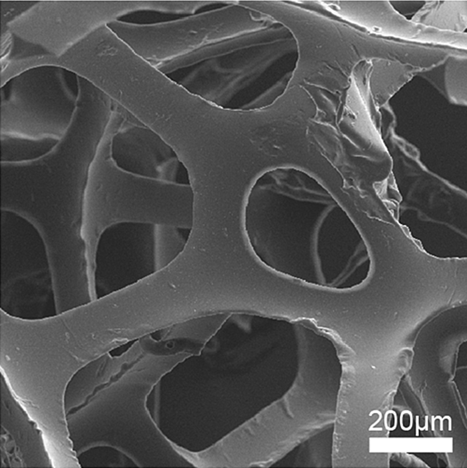
SEM image of a representative polyurethane scaffold without cells. SEM, scanning electron microscopy.
PU scaffolds showed a very high porosity of 97.1%±0.6%, a strut thickness of 57.2 μm±16.8 μm, a strut separation of 873 μm±59.3 μm, and a strut number of 1.2/mm±0.1/mm.
Endothelial cell location on 3D PU
HDMECs were grown in 3D culture on PU scaffolds. Location and distribution of typical antigens on HDMEC surfaces were studied by immunocytochemical staining and CLSM. The expression of CD31 (platelet endothelial cell adhesion molecule-1) was observed most intensely at endothelial cell–cell interfaces, illustrating the characteristic cobblestone structure-like growth of HDMECs (Fig. 3A). A separate picture shows the distribution of HDMEC nuclei on PU scaffolds (Fig. 3B). Staining for CD34 (sialomucin), expressed by hematopoietic and vascular-associated cell surfaces, revealed that antigen expression was distributed across the cell surfaces (Fig. 3C). Controls at same excitation settings without primary antibody or plain PU scaffolds showed only background noise (Fig. 3D, E). Staining of plain PU and human mesenchymal stem cells with both antibodies for CD34 proved to be negative (data not shown).
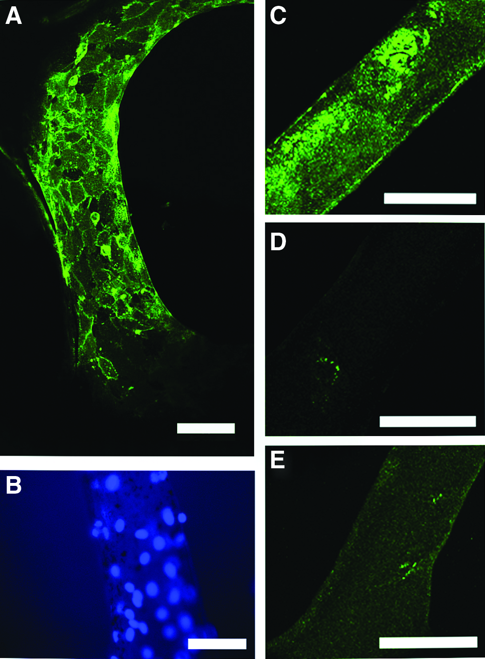
Immunocytochemical stainings of HDMECs grown for 6 days on PU scaffolds.
FeO labeling of HDMECs on 2D PS
Light microscopic images of Prussian Blue-stained FeO particles, coupled to HDMECs on PS, revealed a group-like binding of FeO particles close to the HDMEC nuclei (Fig. 4A, B). Cell labeling with FeO particles was dependent on CD34 expression using a biotinylated antibody. SEM imaging of FeO-labeled HDMECs on PS revealed the binding of FeO with heterogeneous FeO particle size (Fig. 4C, D), representing FeO particles abiding to the product specification sheet (0.5–1.5 μm), but further revealed large (up to ∼50 μm), squared FeO crystals (arrow, Fig. 4D), spread over the cell-covered surface. SR CT imaging was able to detect FeO particles (Fig. 4E, F) and also confirmed the presence of both the small and the larger squared crystals (arrow, Fig. 4F). For both methods, SEM and SR CT, particle size and distribution over the surface area matched well. Large, squared particles were rarely observed in the light microscopic images, resulting from an additional treatment with Prussian Blue solution, thereby removing most of the large FeO particles. FeO particle labeling of plain PS and human mesenchymal stem cells as controls proved to be negative (data not shown).
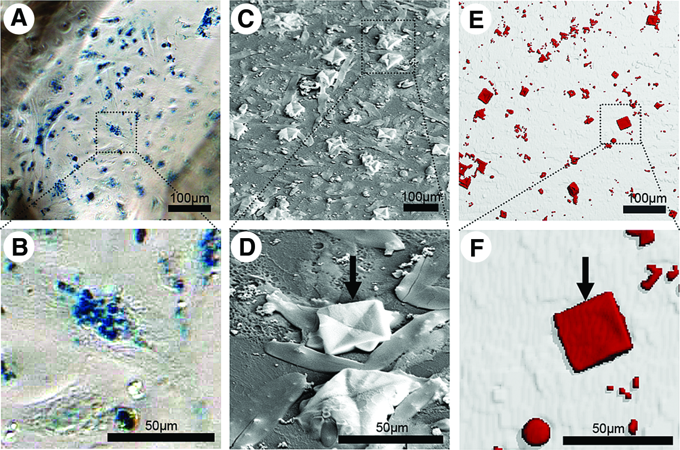
Images of cell-coupled FeO particles on microvascular endothelial cells grown on two-dimensional (2D) Petri dish surfaces. Cell labeling with FeO is dependent on CD34 expression using a specific biotinylated antibody.
FeO labeling of endothelial cells on 3D PU
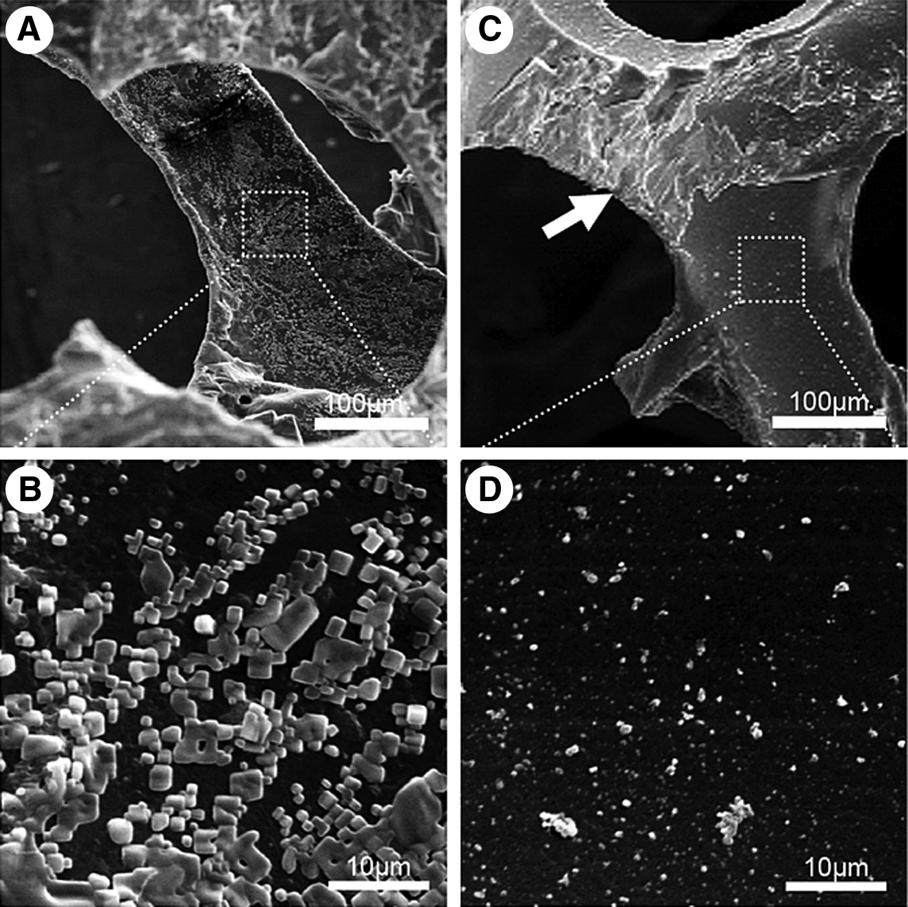
SEM images were taken of FeO-labeled HDMECs grown on 3D PU scaffolds. Random sites on PU struts within the scaffold were chosen for imaging. SEM revealed dense packing of FeO crystals to cell-covered surfaces (Fig. 5A, B); in addition, large FeO plaques or large crystals were detected. Control scaffolds without cells showed some unspecific particle adhesion to the surface, but comparatively fewer FeO particles per surface area (Fig. 5C, D). Likewise, FeO plaques could be observed covering some parts of the scaffold surface (arrow, Fig. 5C).
SEM images of
FeO-labeled HDMECs on 3D PU scaffolds were subsequently imaged by SR CT, which revealed binding of FeO to cell-seeded PU scaffolds (Fig. 6A). To virtually remove FeO plaques and large FeO crystals (arrow, Fig. 6A), image processing was applied, resulting in single FeO clusters distributed over the PU surface (Fig. 6B). Scaffolds without cells but labeled with FeO particles as well showed comparatively fewer FeO particle attachments (Fig. 6C). Control images of plain PU scaffolds stained negative for FeO voxels (Fig. 6D).
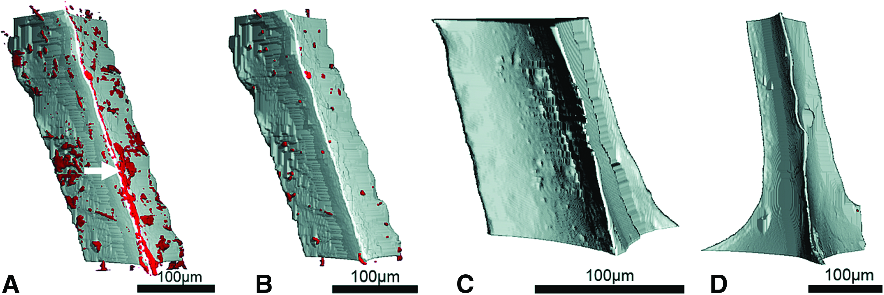
Representative SR CT images of struts of PU scaffolds seeded with HDMECs and labeled with primary anti-CD34–biotin antibodies and FeO–streptavidin particles (arrow, FeO crystals) before
Next to qualitative images, quantitative analysis of FeO-labeled HDMECs on 3D PU scaffolds was implemented with SR CT. A quantitative, statistical analysis of the amount of FeO particles bound to PU scaffolds showed that significantly more FeO particles and voxels per scaffold surface were counted on PU scaffolds with FeO-labeled HDMECs compared with PU scaffolds without cells but with FeO particles or plain PU scaffolds (Fig. 7A, B), showing that specifically bound particles can be clearly distinguished with this method from possible unspecifically bound particles. The same significant results were obtained for the amount of FeO particles and voxels per PU scaffold volume (Fig. 7C, D). It can be assumed that HDMECs are existent as a monolayer on a 3D PU scaffold surface (Fig. 3A); therefore, the amount of FeO particles/voxels per PU surface/volume presents an indirect measure of cell number. Doublestaining of the CD34 epitope with a fluorescent antibody as well as with FeO was not feasible. Further, as struts were selected randomly within the PU foam for SR CT imaging, there was no possibility to find the same location by CLSM. CLSM would additionally be limited by spatial access to the struts within the PU scaffold. Therefore, no correlation between the cell number and FeO particles/voxels per PU surface/volume and CD34 (antigen) expression and antibody binding (FeO particles) could be retrieved.
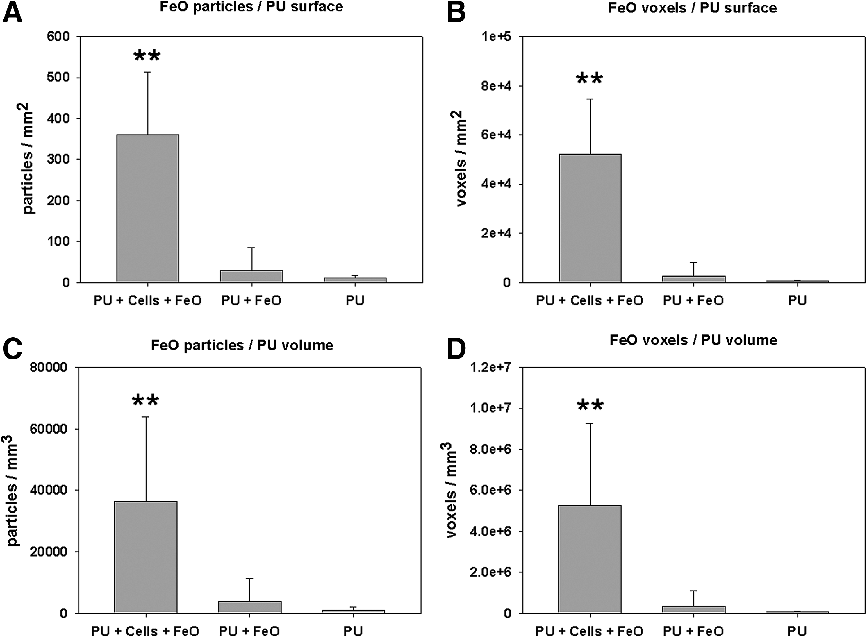
Quantitative results of FeO-labeled HDMECs grown for 6 days on PU scaffolds as determined with SR CT.
Discussion
The aim of this article was to establish and test a novel cell-labeling method for high-resolution CT. According to Figure 1, the labeling approach is similar to an indirect ELISA or immunohistochemical method, where a primary antibody specifically binds to a cell surface antigen followed by a secondary antibody that will bind to the primary antibody. As we did not permeabilize the fixed cells, we believe that the labeling agent is not within the cell or the cell membrane but on the outer cell membrane, as is also shown by the SEM images. The streptavidin-coupled FeO particle is able to bind to the primary antibody by its strong biotin–streptavidin noncovalent interconnection. A streptavidin monomer exhibits a weight of 16.8 kDa and an affinity of Ka ∼1014–1015/M toward biotin (244 Da), also known as vitamin H. This affinity is 103–106 times greater than for the interaction of ligands with their specific antibodies, 27 demonstrating the capability of a strong binding of micrometer sized particles. Streptavidin and biotin represent exceptionally stable molecules, and their biotin-binding activity can survive harsh reaction conditions, 27 important for reliable FeO labeling. The same streptavidin–biotin interaction, used as a detection system, is commonly exploited in affinity chromatography, immunological assays, gene probes, DNA-chip technology, cell cytometry, hybridoma technology, and blotting technology. According to the producer specifications, the used FeO labeling agent is normally used for the extraction of biotin-containing proteins or DNA-binding proteins in liquid solutions. The bound FeO particles are extracted by magnetic fields. The idea was to modify the application of this method by using this agent for the labeling of in vitro-cultivated and -fixed cells. Our experiment primarily focused on the feasibility of FeO particle labeling of fixed endothelial cells on 2D and 3D surfaces and subsequent imaging of FeO particles by SR CT. The use of Prussian Blue solution served not only to stain FeO particles but also to assess whether FeO particles endure multiple washing cycles after cell labeling. Thus, the binding stability was indirectly tested. From our observations, FeO particles stayed attached to each cell surface membrane after cell labeling, Prussian Blue staining, and surface washings. Streptavidin and biotin per se constitute a very strong binding affinity. No further information exists on how strongly streptavidin stays attached to the FeO particles and how long the particles ultimately stay attached to the cell surfaces. However, it was shown that particles stayed attached to cells after surface washings to successfully label the cells for subsequent SR CT imaging. It should be noted that other FeO particles exist, which are exclusively made for cell labeling, such as streptavidin-labeled FeO nano beads showing homogenous bead size. This sort of FeO beads (<1 μm), however, was not applicable to our experimental setup due to resolution limitations with SR CT.
Endothelial cells have been used in this labeling system because endothelial cells are an abundant cell source in the human organism and play a significant role, for example, in cancer evolution and vascularization of tissue-engineered products.28,29 The labeling system was designed for in vitro application but could potentially be used for in vivo/ex vivo targets as well. The in vitro application of this method presents a limitation that needs extensive research whether an in vivo use is intended. An in vivo application would require thorough testing of particle cytotoxicity and cell proliferation as well as the harmfulness of SR CT radiation on living cells. By substitution of the biotinylated primary antibody target to another cluster of differentiation (CD) antigen, theoretically, every cell type, or even tissues, could be FeO labeled if they provide accessibility for the rather large complex. The labeling system could theoretically be utilized to label single or multiple cell colonies in two dimensions or three dimensions or to label any other structures of interest.
So far, conventional cell imaging mostly reverted to cell staining by fluorescent or bioluminescent proteins followed by high-resolution light microscopy, such as CLSM imaging. These staining and imaging methods, however, were mainly designed for imaging of cells on 2D surfaces, also being restricted to peripheral scaffold surfaces on 3D scaffolds.4,30 Cell-seeded areas within 3D scaffolds are normally excluded from light microscopical examination, which limits light microscopy to a great extent. Thus, interesting areas within larger tissue-engineered constructs are excluded from optical imaging. From this point of view, our cell imaging method was set to use CT, which allowed imaging of PU scaffolds and screening for cells in areas inaccessible to light microscopy. High-resolution CT and particular SR CT has the advantage of yielding highly resolved images down to the submicrometer level at quick measuring times, being at the same time a nondestructive imaging technique. However, CT has disadvantages in its dependency on fixed tissues, thus excluding living objects and tissues. For CT imaging of soft tissues, cell or tissue labeling/staining by gold-labeled lectins or heavy metal solutions, such as OsO4, can be applied to increase the X-ray absorption of the cells under investigation.31–33 Due to the overall staining by toxic OsO4 or the unspecific cell labeling by gold-labeled lectins, the usage of nontoxic, streptavidin-coupled FeO particles were applied to circumvent the latter disadvantages. FeO particles (∼1 μm in size) pose a resolution problem to common clinical CTs, which were solved by high-resolution CT to image FeO particles in this labeling system. The mass attenuation coefficient indicates how strongly a chemical species or substance absorbs or scatters X-rays at a given wavelength, per unit mass. 34 With an FeO mass attenuation coefficient of 769.3 [1/cm], PU of 0.55 [1/cm], and PS of 2.24 [1/cm], FeO absorption is about 340–1400 times higher than PU and PS, and thus an image contrast could be established for the segmentation of cell growth substrate and FeO particles in this experimental setup.
The used PU scaffolds provide ideal endothelial cell growth conditions, presenting smooth surfaces, comparable to Petri dish surfaces. Similar cobblestone-like endothelial cell growth has been observed on PS or on other biomaterials. 25 The highly porous PU scaffold also eases cell seeding and access of HDMECs to the innermost scaffold parts, thus yielding a cell surface coverage of the full 5×5×5 mm scaffold disk after only 6 days of in vitro culture. The high porosity of the PU scaffold allowed easy imaging of single struts for further evaluation and quantification.
Examination of HDMEC-specific antigen expression of cells growing on PU scaffolds by immunocytochemistry and CLSM revealed normal cell wall protein expression, such as CD31, primarily formed at intercellular junctions. 25 Oval-shaped cell nuclei show the presence and cell density on PU scaffolds after 6 days of incubation. As CD34–biotin antibodies have been applied in the implementation of our cell-labeling method, immunocytochemistry of this antigen coupled to a fluorescent marker was evaluated too. Compared with CD31, being predominantly expressed at cell–cell boarders, CD34 is expressed across the whole cell surface and thus demonstrates a more suitable antibody for FeO-labeling. CD34–biotin can further be applied for other cell types, such as for early hematopoietic progenitor cells. 35 Compared with plain PU scaffolds or cell-cultivated PU scaffolds without CD34 primary antibody application, only HDMECs with both first and fluorescent secondary antibody showed positive CD34 antigen expression, which justified the use of biotinylated CD34 antibodies in this novel method.
The FeO-labeling of HDMECs on a flat 2D PS surfaces showed a close binding of FeO particles primarily to the cell centers. Figure 4A and B shows that FeO particles, made visible by Prussian Blue staining, can label HDMECs individually and thus could account for the total amount of cells present by FeO colony counting. No FeO particle colonies have been observed on PS free of cells (data not shown here). SEM images of FeO-labeled samples showed a heterogeneous FeO particle size, ranging from ∼1- to ∼50-μm particles, squared crystals (Fig. 4C, D), presenting a limitation of this experiment. This heterogeneous population of FeO particles was also visible in the SR CT images of 2D PS surfaces (Fig. 4E, F). On the 3D SR CT images, crystals larger than 15×15 μm2 and any larger accumulations of crystal compounds have been classified as plaques and have been eliminated in the images by in-house filtration software. With these experiments we could confirm that labeling of HDMECs with FeO particles in 2D on PS was feasible and that the particles can be segmented from the plastic surface to locate the cells. Future work in labeling cells with FeO particles should be performed under the precondition of particle filtering to eliminate abnormal particles in advance. Further improvements in FeO incubation to label each cell equally well, as well as optimization of the particle washing process afterward, are desirable to additionally refine this labeling method.
SEM images of cell-seeded PU scaffolds revealed that FeO particles covered most of the surface. Due to manual scaffold washing, not all unspecific particles may have been washed away leaving a pattern not fully comparable to the pattern on 2D PS. In general, such washing steps are even more difficult in 3D due to the hindered access to the inner volume of the scaffold. Next to truly FeO-labeled HDMECs on PU surfaces, large FeO plaques covered some parts of the PU scaffold (Fig. 5C).
SR CT was able to image attachment of FeO on cells cultured on PU scaffolds. Using segmentation techniques, it was possible to visualize both the 3D scaffold structure and the FeO particle distribution over the surface of the scaffold in parallel. Statistical analysis has shown significantly more FeO particles/voxels on PU surfaces/volumes than on scaffolds without cells or plain scaffolds only (Fig. 7A–D). Component labeling erased all connected particles larger than 1925 voxels, that is, the size of the smallest squared FeO crystal classified as plaque. The spot-like FeO depositions (Fig. 6B) most likely represented clusters of several small FeO particles bound to HDMECs. To exclude possible partial volume effects for the FeO segmented fraction, a single erosion/dilation cycle has been implemented, which removed and added a single voxel layer from the virtual FeO particles. This entailed additional elimination of true, single voxel FeO particles, thus losing important information of labeled HDMECs. It was considered important to finally image true FeO voxels instead of quantifying false-positive partial volume effects. The indicated FeO clusters in Figure 6B therefore represent the relative amount and not the absolute amount of HDMECs. Virtual filtration therefore might result in cells that are present, but are not detected, presenting a limitation in this experiment. Additionally, multiple particles could attach to a single cell. Cell number has not directly been quantified using histology to state whether the calculated number of cells is directly correlated with the real cell number. Future studies should be directed to find out if a constant FeO particle signal per cell could be measured after a more homogeneous FeO-labeling agent has been developed. The general low absorbance of PU resulted in partly hollow, 3D PU scaffolds after thresholding (data not shown). These needed to be computationally filled after surface masking to regain a voxel-filled PU body for subsequent surface and volume calculations.
Conclusion
This article introduces a novel cell-labeling method for absorption-based high-resolution CT, which was demonstrated using fixed endothelial cells on 2D PS and 3D PU scaffold surfaces. This method, which exploits a biotin–streptavidin–FeO antibody binding system toward HDMEC surface antigens, enabled imaging of cellular distribution on 3D scaffolds. Detection of particles specifically bound to HDMECs, as well as segmentation of those particles from the surface, was possible. This method enables the determination of the location and quantitative distribution of HDMECs on different surfaces. Significantly more FeO particles could be bound to the cell-seeded surfaces in a cluster-like mode. After further optimization of this labeling method, it could potentially be employed in in vitro labeling of different cell types and imaging of cellular structures, such as capillary networks on substrate surfaces. Although high-resolution absorption-based CT currently excludes imaging of living objects, our method could potentially be applied ex vivo in labeling of antigens at FeO-antibody accessible sites, such as antibody-perfused vascular structures with successive high-resolution CT detection and imaging for vascular characterization.
Footnotes
Acknowledgments
The authors acknowledge funding from Angioscaff, EU Seventh Framework Program (FP7-NMP-2008-214402). We thank Drs. Davide Ruffoni and Martin Stauber for advice in CT image processing. PU scaffolds were kindly provided by KCI Medical GmbH, Rümlang, Switzerland.
Disclosure Statement
No competing financial interests exist.