




Abstract
Long-term in vivo studies on animal models and advances from animal to human studies should rely on noninvasive monitoring methods. Synchrotron radiation (SR)-diffraction enhanced imaging (DEI) has shown great promise as a noninvasive method for visualizing native and/or engineered tissues and bio-microstructures with appreciable details in situ. The objective of this study was to investigate SR-DEI for in situ visualization and characterization of tissue-engineered scaffolds implanted in cartilage. A piglet stifle joint implanted with an engineered scaffold made from poly-ɛ-caprolactone was imaged using SR computed tomography (CT)-DEI at an X-ray energy of 40 keV. For comparison, in situ visualization was also conducted with commonly used SR CT-phase contrast imaging and clinical magnetic resonance imaging techniques. The reconstructed CT-DE images show the implanted scaffold with the structural properties much clearer than those in the CT-PC and MR images. Furthermore, CT-DEI was able to visualize microstructures within the cartilage as well as different soft tissues surrounding the joint. These microstructural details were not recognizable using other imaging techniques. Taken together, the results of this study suggest that CT-DEI can be used for noninvasive visualization and characterization of scaffolds in cartilage, representing an advance in tissue engineering to track the success of tissue scaffolds for cartilage repair.
Background
A
At the current experimental stages of cartilage TE, conventional histological and imaging techniques, such as light microscopy, scanning electron microscopy, transmission electron microscopy, and confocal laser microscopy, are typically used to visualize and study the success of the tissue-engineered scaffolds. These conventional methods are destructive and involve invasive analysis, for which the animal model should be sacrificed. For long-term animal studies, a large number of animals are required for sacrifice throughout the experiments, which makes in vivo studies expensive and complicated. Furthermore, since TE strategies will eventually advance from animal to human studies, noninvasive visualization of scaffolds and new tissue generation becomes essential. Although a large number of TE studies have been targeting cartilage tissue, the development of noninvasive monitoring methods with application to cartilage TE has received limited attention.
Diffraction enhanced imaging (DEI) is an X-ray imaging technique that has shown great promise for nondestructive, quantitative, and qualitative visualization of soft tissues with detailed internal structures. DEI contrast is based on the refraction of X-rays, rather than absorption/attenuation as they travel through the object being imaged. This makes DEI a suitable technique for imaging TE scaffolds and constructs as well as soft tissues (e.g., cartilage) that have very low X-ray attenuation. The main advantage of DEI is that the images can be captured noninvasively and without any exogenous contrast agents. DEI is capable of resolving histological and structural details of articular cartilage,4–7 which are not easily visible using conventional imaging techniques based on absorption contrast. Cartilage consists of ∼80% water and, as such, is invisible in conventional radiographs. This is also true for TE scaffolds and constructs made from low-density materials.6,8 Magnetic resonance imaging (MRI) and ultrasound are two additional, well-known medical imaging techniques. However, they exhibit some inherent limitations or disadvantages for imaging soft tissues and low-density materials such as cartilage, 9 including the limits on spatial resolution and the types of tissues/structures that can be resolved. Consequently, investigation of alternative noninvasive imaging techniques (such as DEI) that can overcome these limitations is greatly needed.
With its higher spatial resolution than MRI, synchrotron radiation (SR)-DEI offers considerable promise for providing detailed information of tissues and microstructures. 10 In-line phase contrast imaging (PCI) 11 is one SR X-ray imaging method based on similar, but simpler than DEI, principles and, thus, offers easier imaging modality. Due to its simplicity and ability to visualize microstructural details in various biological tissues and TE scaffolds,12,13 PCI has been commonly used in TE. However, in most reported studies, DEI and PCI have been used for imaging TE scaffolds in the in vitro or non-in situ-like conditions. Examples include imaging of dehydrated TE scaffolds in air12,13 and in thin tissue representative medium. 8 Although these studies demonstrate the potential of these techniques, their capacity for real in vivo TE studies has not yet been investigated and reported. Planar or two-dimensional (2D) DEI and PCI have recently been investigated for visualization of low-density TE scaffolds embedded in muscle tissue with a sample thickness of approximately 4 cm. 8 As the tissue sample becomes thicker (more than 4 cm), visualization of the scaffold may become questionable by using these 2D imaging techniques. With the advance of computed tomography (CT), it is rational to combine these imaging techniques with CT to potentially overcome this limitation with improved capacity for visualization of TE scaffolds in thick tissue samples or in situ. To the best of the authors' knowledge, to date there have been no studies reported in this regard. As such, the objective of this study was aimed at investigating CT-DEI for visualization and characterization of TE cartilage scaffolds in situ, compared with CT-PCI and clinical MRI, so as to identify the most appropriate imaging technique for use in noninvasive and serial in situ monitoring of TE cartilage repair.
Materials and Methods
Scaffold fabrication
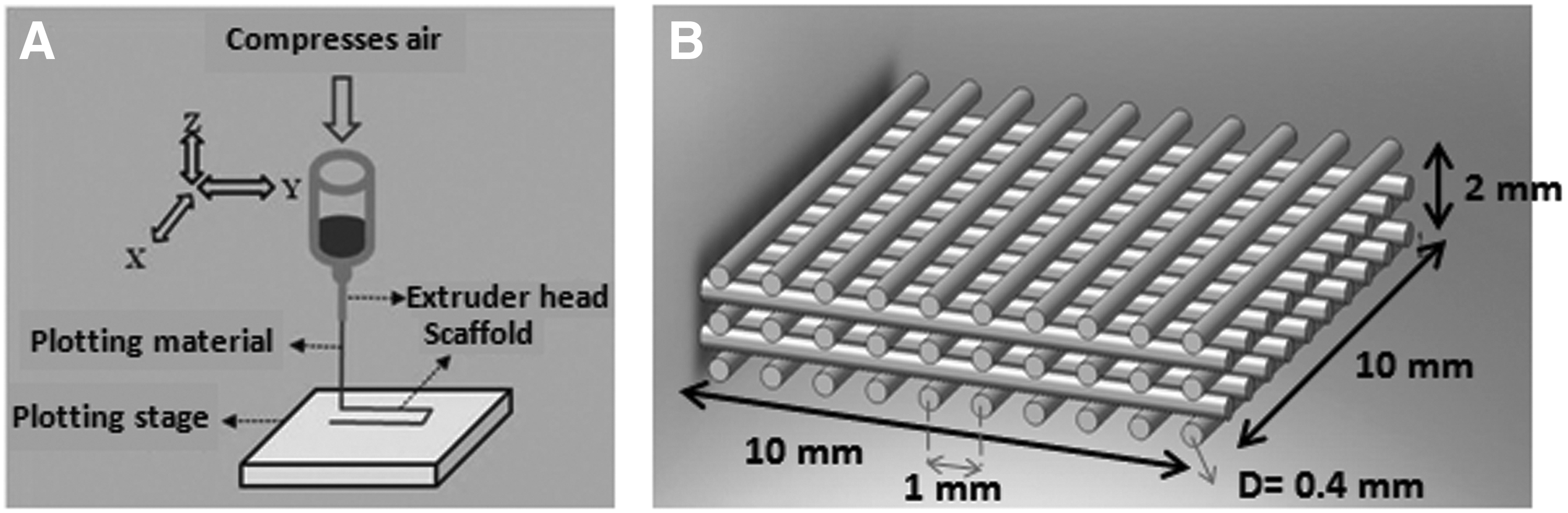
The scaffold used in the present study was designed with a porous structure and then fabricated on a 3D-Bioplotter (Envisiontec GmbH). The Bioplotter is a three-axis, computer-controlled additive manufacturing system that can build 3D scaffolds from a variety of biomaterials. Poly-ɛ-caprolactone (PCL) (Mw 48,000–90,000; Aldrich) was chosen for the scaffold fabrication due to its wide applications to cartilage TE. PCL was melted at 65°C in the high-temperature dispensing head of the Bioplotter and was subsequently dispensed through a metal needle with an internal diameter of 400 μm under a pneumatic pressure of 0.75 MPa (Fig. 1A). Scaffolds were fabricated by dispensing melted PCL strands in multiple layers with a strand spacing of 1 mm and a 0°/90° pattern of successive layers (Fig. 1B). The scaffold was originally fabricated with an overall size of 10×10×1.7 mm and was then trimmed to 4×4×1.7 mm for implantation.
Sample preparation
Pig joints are usually used for in vivo cartilage TE studies 14 , because they better simulate human conditions than small animal models. In this study, the piglet stifle (knee) joint was selected to investigate the noninvasive imaging. Dissected stifle joints of 4-week-old cadaver piglets were prepared at the Vaccine and Infection Disease Organization (VIDO). For each sample, a full-thickness articular defect (4.5×4.5×2–2.5 mm depth) was created in the lateral femoral condyle cartilage of the knee, and a scaffold as prepared earlier was then implanted into the created defect area and covered with a piece of periosteum layer, 14 which was concurrently harvested from the proximal femur (Fig. 2), to mimic the actual surgical procedure used in animal and clinical studies. During the implantation surgery, joint cavity fluid was released and as a result, air entered the joint cavity and the surrounding soft tissues. It is noted that the trapped air may misrepresent in vivo conditions and cause artifacts in the images. As such, the trapped air should be removed from the joint samples before being imagined. For this, joint samples were placed in a sample holder filled with Dulbecco's phosphate-buffered saline, which was then placed in a vacuum desiccator for 10–15 min to remove trapped air. It is noted that in live animal/clinical studies, the trapped air may be gradually absorbed and removed from the site via the vascular system/blood circulation postsurgery, and then replaced with synovial and body fluids.

Surgical approach used for implanting tissue engineering (TE) scaffolds in the lateral femoral condyle cartilage of the knee in dissected piglet joints. Color images available online at
Synchrotron-based imaging
Imaging was performed at the Biomedical Imaging and Therapy bend magnet (BMIT-BM) beamline of the Canadian Light Source (CLS). A highly collimated X-ray beam was produced by a bend magnet (1.354T) and monochromatized at 40 keV photon energy by a Si(4,4,0) double crystal monochromator. It is noted that the imaging photon energy is determined by the thickness of tissue sample being imaged, that is, thicker the sample is, the higher photon energy is required. Based on our previous studies,8,15 40 keV photon energy and the analyzer reflection plane of Si(4,4,0) were selected and expected to be able to visualize the samples as prepared in this study. A Photonic Science detector with an effective pixel size of 37×37 μm2 was employed to collect the images, which was selected based on the balance between the area of interest in the sample and the image resolution, as well as the availability of detectors at the CLS. For each sample, CT images were acquired by rotating it 180° around an axis perpendicular to the incident beam with an angular scanning increment of 0.072°. During the process of imaging, both the beam and detector were stationary and the detector acquisition system was synchronized with the sample angular scanning. The size of the scanned region (field of view) at the detector was 4 mm (vertical)×74 mm (horizontal). The time required for imaging one sample was 4.9 h for CT-DEI and 1.7 h for CT-PCI. The principles behind both CT-DEI and CT-PCI are outlined as follows.
CT-DEI
DEI can dramatically increase the contrast of X-ray images by utilizing a crystal analyzer that enables contrast mechanisms of refraction, ultra small angle X-ray scattering, and scatter rejection of small angle X-ray scattering in addition to the absorption mechanism.
4
When the X-rays travel through the sample, they are refracted at the interfaces of organized features/structures in the tissue through angles of a few microradians. The analyzer placed between the object and the detector (Fig. 3) uses its angle-dependent reflectivity, or rocking curve (RC), to tune the diffraction of refracted, transmitted X-rays off the analyzer to the detector. At the detector, this is translated into enhanced contrast at the interface of features having different densities from their surroundings. A detailed description of the DEI method can be found in.
16
To obtain DEI refraction images, two sets of images were taken: one on the low angle side (the low-angle image [L]) and one on the high angle side (the high-angle image [H]) of the half maximum point of the analyzer RC (Fig. 3). On each side of the RC, tomographic images were acquired by taking 2500 projection images from angular scanning. For normalization of images, flat field (beam without sample) and dark field (without beam) images were also taken at both sides of RC. Refraction angle images were then calculated using the following equation
16
:

Schematic of the diffraction enhanced imaging (DEI) set up at the Canadian Light Source used for imaging TE scaffolds in piglet joints. Embedded graph shows the analyzer rocking curve, in which X-ray reflectivity from the analyzer is a function of incident angle.
where ΔθZ is the intensity in the refraction angle image, R(θ) is the analyzer reflectivity, θ is the analyzer angle, and IH and IR are the intensity of the images taken on high-angle side (θH) and low-angle side (θL), respectively. Obtained refraction images were then processed using SYRMEP software (Elettra Synchrotron Facility) to create CT slices, which were then 3D rendered using Avizo® software (VSG).
CT-PCI
PCI exploits X-ray refraction at the edges of different features to provide higher image contrast. In in-line PCI, this is made possible by providing a free space between the sample and the detector so that the refracted, transmitted X-rays can freely propagate and interfere to develop informative phase-shifted signals at the detector. SR provides high coherence X-rays, which is essential to enhancing the quality of PC images. Briefly, the X-rays travel through the object, with the phase information of the beam disturbed by interfaces of features inside the sample that have differing refractive indexes. The phase variation propagated in the free sample-to-detector distance is converted into intensity variation at the detector to visualize the structural features in the object. For PCI of the pig joint samples, a sample-to-detector distance of 85 cm was used. Multiple (3000) images were acquired by rotational (angular) scanning of the sample. Flat field and dark field images were also taken for normalization. Tomographic slices were reconstructed following the same procedure as for CT-DEI.
Magnetic resonance imaging
MRI of joint samples was performed at the MRI Center, Royal University Hospital (Saskatoon, Canada). The MRI imaging system was a 3T Siemens MAGNETOM® MRI Skyra, with XQ gradients and 48 channels. T2-weighted spin-echo sequence was used for taking the image, and the imaging receiver employed was a hand/wrist 16 channel high-resolution receiver coil with a “clamshell design.” By using MRI, the time required for imaging one sample was 4 min. Images obtained by MRI were processed by using Numaris/4 software (syngo MR D11).
Results
Scaffold characterization
Images of the PCL scaffold fabricated for implantation are shown in Figure 4. The grid structure and morphology of the PCL scaffold are visible from stereo microscope (Ancansco) image at 2X magnification (Fig. 4A). The size of the fabricated scaffold in the z direction is indicated in the isometric view of the scaffold taken by digital camera (Fig. 4B). It is noted that the computer-controlled fabrication technique employed in the present study allows for reproducibility of scaffolds with the designed structure and properties, thus limiting the variability of samples for imaging.

Images of the fabricated PCL scaffold by a stereo microscope at 2×magnification
Planar DEI
Using the DEI technique, absorption images were obtained along with refraction images. As expected, the absorption image did not provide enough contrast for visualizing the low-density scaffold and surrounding tissue microstructures. Consequently, the refraction image, which achieves its contrast solely from refraction of X-rays, is of interest in this study and is exclusively discussed next (referred to as the DE images).
A planar refraction image obtained from the 2D-DEI of the sample shows a 15 cm long sagittal view of the joint (Fig. 5). The planar refraction image was acquired to compare the visibility of the cartilage scaffold in situ using 2D imaging modality to tomographic imaging. A weak grid profile of the scaffold can be recognized in the planar DE image (Fig. 5); however, the contrast is obviously not sufficient for clear visualization. The limited contrast of the scaffold image may be due to the nature of 2D imaging, in which superposition of information over the thickness of the sample can hinder distinct differentiation of the scaffold structure. As expected, quantitative characterization of scaffold structural properties was also not possible in 2D-DEI. Furthermore, the images of the scaffold which show its grid structure (e.g., Fig. 5) can only be acquired in limited projection shots, that is, at specific spatial/angular positions of the scaffold and the joint itself, but this is inconvenient and impractical. CT imaging can overcome these limitations by producing volumes of data that are used to generate 3D images of the sample.
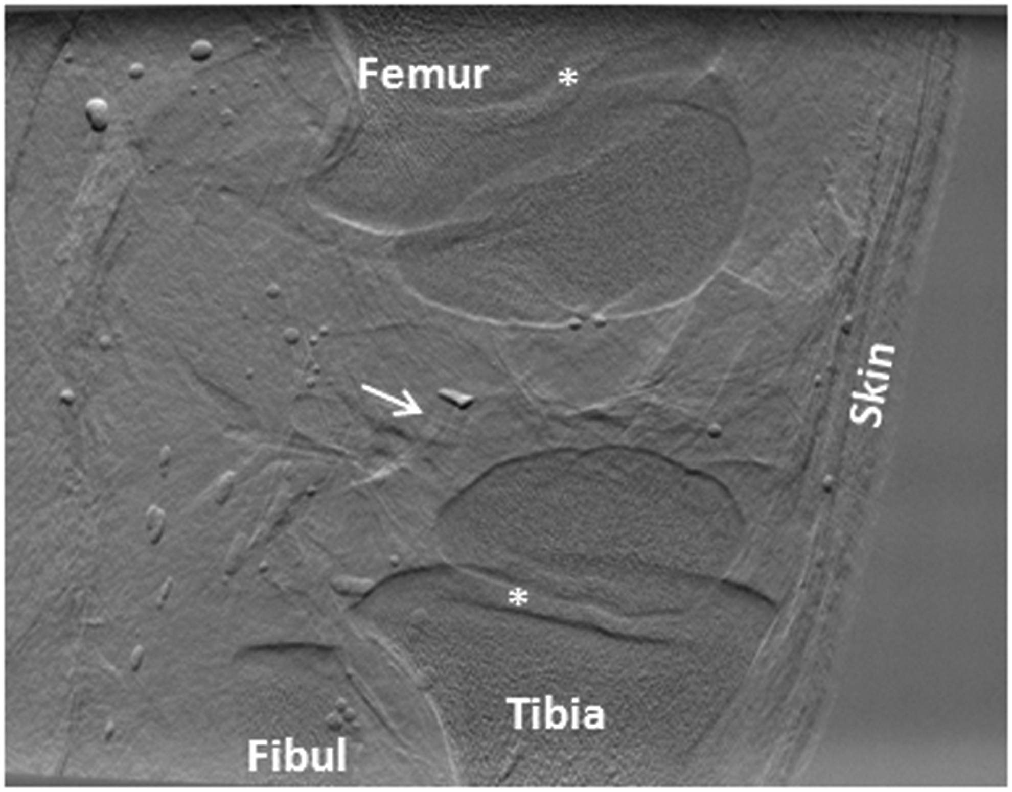
Sagittal image of the pig joint using 2D-DEI; the white arrow points to the implanted scaffold in the lateral femoral cartilage. Asterisk (*) indicates the growth plate in a growing joint.
Computed tomography DEI
A volume image was reconstructed from the CT-DEI of the sample. The refraction image of a representative slice (Fig. 6) shows a profile through the cartilage of lateral and femoral condyles as well as surrounding soft tissues (e.g., skin, muscle, fat). The interfaces of different soft tissues as well as microstructures of the skin and the infrapatellar fat pad can be identified in the DE image (Fig. 6A). In the enlarged image showing the condyles (Fig. 6B), a cross-sectional view of the PCL scaffold is clearly recognizable in the lateral femoral cartilage. The PCL strands and their 0°/90° grid pattern of the scaffold structure are clearly visible in the image. Notably, the enhanced contrast at the edges of the strands makes the scaffold contour visible and distinguishable from surrounding low-density tissues. In addition to the implanted scaffold, the DE images show the information on tissue features, including the morphological or structural features of the cartilage (e.g. different appearance of the cartilage tissue in the inner area of the femoral condyle) and the vascular channels within cartilage (Figs. 6B and 9A).

Representative tomographic DE image of a pig knee joint implanted with a TE scaffold in the cartilage (image pixel size 37 μm):
A 3D-rendered image of stacked tomographic slices created a volume image of the joint with a thickness of 4 mm about the region of implantation (Fig. 7). The surfaces of the condyle cartilage at an axial view of the joint are visible (Fig. 7A), with the recognizable structural pattern of the implanted scaffold (Fig. 4A) clearly depicted in the lateral condyle cartilage. Branches of vascular channels throughout the lateral condyle cartilage are also easily identified in the 3D rendered image. The vascular branches in the medial condyle cartilage are visible in other views (not shown here). While the cartilage vascular system is most evident in young growing joints, these images show the obvious potential of DEI for visualizing detailed microstructures in soft tissues. An enlarged 3D rendered image of the scaffold (Fig. 7B) provides a clear image of the scaffold structure in which some structural properties, such as strands and pore sizes, can be quantitatively characterized. This is of special interest for in vivo evaluation of the degradation and mechanical properties of scaffolds during the repair process. For example, one can employ finite element models that use measurable structural parameters as input for simulations that evaluate changes in scaffold mechanical properties with time. 17 Interestingly, even the surgical suture that was used for suturing and closing the inner site of incision was visualized in the DE image (Fig. 7B). Furthermore, the soft periosteum tissue layer used to cover and fix the scaffold in place was visible in the CT-DE images (Fig. 7C). These are features that can hardly be visualized at this detailed level, if at all, using other imaging techniques. Figure 7A shows the presence of some air bubbles in the joint, which produces strong contrast against other anatomical features imaged in the joint. Although the vacuum dessicator removed the majority of air bubbles from the joint, some remain due to the limited vacuum duration and the formation of bubbles from boiling of the joint sample in the vacuum. The streak artifact that is seen around the scaffold in Figures 6 and 7 is caused due to a small copper wire that is used for quickly locating the scaffold in the joint for the CT scan.
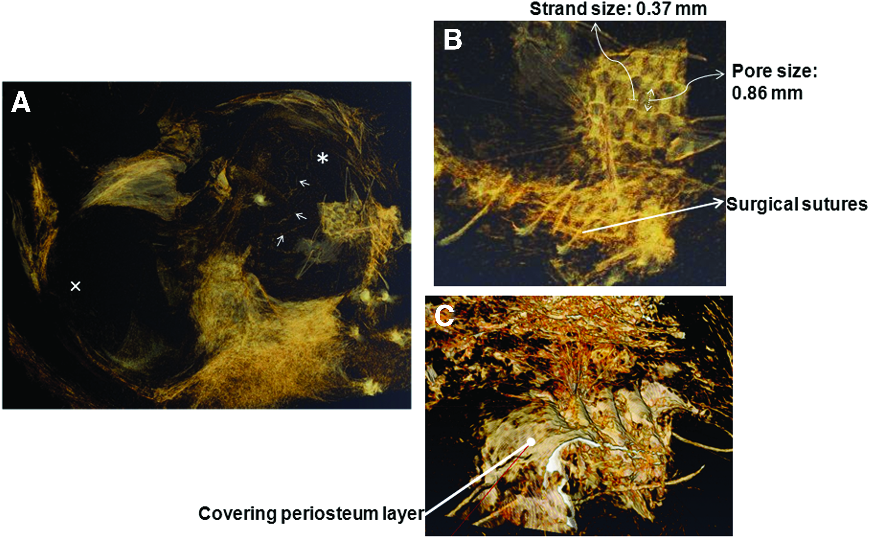
Volume-rendered DE image of the joint at the site of implantation:
DEI compared with PCI and MRI
The three imaging techniques—CT-DEI, CT-PCI, and MRI—were compared with regard to visualization of the PCL scaffold in cartilage in situ (Fig. 8). Slices through the joint at the site of implantation were obtained for CT-PCI (Fig. 8A) and CT-DEI (Fig. 8B). Although the two images represent the same axial view of the joint, the scaffold cannot be perceived in the PC image; however, the DE image clearly shows a profile of the scaffold structure. Structural features in the cartilage and surrounding soft tissues that can be recognized in the DE image (Fig. 8B) are not visible in the PC image (Fig. 8A). This includes the contours that clearly distinguish the condyle cartilage from surrounding tissues, interfaces which differentiate various soft tissues, and in-cartilage vascular channels. The PCI-induced contrast can apparently only visualize and differentiate bulk features inside the sample (e.g. fat against nonfat soft tissues) and not the fine features required for visualizing microstructures (e.g., the TE scaffold). Consequently, the tested PCI system is unable to provide the information required for imaging and studying TE scaffolds for cartilage repair in situ.

Comparison of
The MR image was taken at a resolution of 310 μm pixels. A representative MRI slice shows a cross section through the condyle cartilage and the location of scaffold implantation (Fig. 8C). The scaffold profile cannot be identified in the MR image and only the contour of the defect created in the cartilage can be depicted. Expectedly, soft tissues such as cartilage, muscle, fat, and skin are visualized and differentiated in the MR image; however, the scaffold is not visible. In fact, the defect area filled with the scaffold is seen as a void black spot in the MR image, which means that an insufficient signal has been produced by the scaffold to make it visible at the detector. Overall, CT-DEI is the most capable method for in situ visualization of scaffolds in cartilage among the three imaging methods for comparison.
Radiation dose
Based on the obtained results, the CT-DEI method evaluated is the most appropriate for visualizing and studying TE scaffolds in thick samples such as knee joints. To extend the application of this imaging method to in vivo studies on live animal models or even future clinical human studies, the ionizing radiation dose received by the sample during CT-DEI should be optimized. The irradiation absorbed by the sample is defined as the deposited energy per mass of material in which the radiation is deposited, and is usually characterized by the rate of radiation dose at the surface of the object where the largest dose occurs. The surface dose rate is calculated using
where
Different tissues and organs respond differently to ionizing radiation based on their radiosensitivity. To account for these differences, a second radiation exposure metric is defined as
where Deff is the effective dose rate in sieverts (Sv) and WF is a weighting factor related to the risk for a particular tissue or organ. Tissue weighting factors associated with different tissues and organs are recommended in the annals of International Commission on Radiological Protection (ICRP). The reported effective dose is usually used for measuring the potential detriment or risk to the radiosensitive tissue. The rate of absorbed surface dose,
Discussion
The results of this study reveal the feasibility of CT-DEI for in situ visualization of a PCL scaffold implanted in pig knee cartilage, which is a critical step to track the scaffold success in the in vivo applications. The combination of CT and DEI technique was found essential for in situ imaging of the scaffolds embedded in thick samples, thus providing a powerful tool for quantitative evaluation of changes in scaffolds during the tissue repair processes. In the present study, cartilage tissue was imaged with appreciate morphological and structural properties by using CT-DEI. As such, CT-DEI could be employed for studying the success of TE cartilage repair in situ by tracking scaffold changes as well as neotissue regeneration. The descriptive information with regard to the cartilage tissue morphology revealed that DE images can also be used for evaluation of the quality of neocartilage as compared with native cartilage. In addition, the CT-DEI presented in the present study was performed without the use of contrast agents or materials. Other methods may be able to provide visual information on the scaffold, but would require the use of contrast materials. In addition to extra work required for scaffold preparation, these contrast agents may also have negative impact on the function of scaffolds and surrounding tissues even after the scaffold completely degrades (i.e., the residual artifact).
In addition to the cartilage tissue targeted in the present study, DEI revealed informative details on the morphology and microstructure of other soft tissues, such as skin, fat, and muscle (Fig. 6A) as well as transverse ligament, anterior cruciate ligament, and menisci (Fig. 9A) (in which the striation and the fibrous texture of the ligaments are clearly visible). Notably, these structural features may not be imaged easily, if at all, using clinical imaging techniques. In addition, it is noted that CT-DEI has the capacity to image hard tissue. For example, Figure 9B is an axial image of the joint, revealing the cartilage and proximal end of the tibia bone; interestingly, the spongy/porous structure of the bone is also visible (Fig. 9B-inset). Simultaneous imaging of both soft and hard tissues demonstrates the promising potential of CT-DEI for TE applications involving a variety of different tissues. This ability is attributed to the nonabsorptive, refraction-based contrast mechanism of DEI. One application of this capability in cartilage TE is to monitor and study the repair at the bone-cartilage interface, which involves both soft and hard tissues.
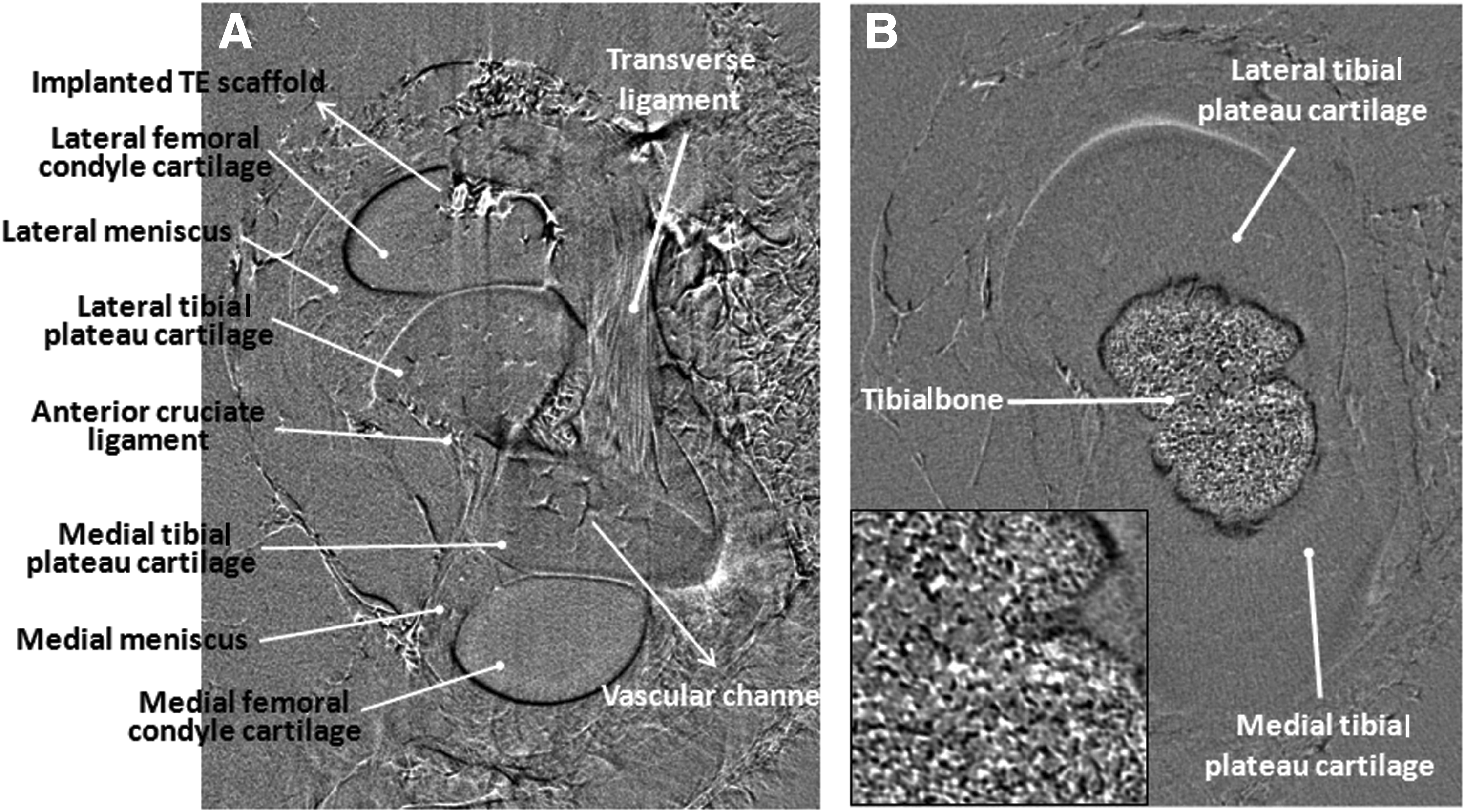
Tomographic DEI slices at two different vertical locations of the joint:
Compared with CT-DEI, CT-PCI has its limit to visualize scaffolds embedded in thick samples as illustrated in the present study. One main factor in the in-line PCI contrast mechanism is the free propagation of distorted X-rays throughout the sample-to-detector distance. A greater distance could improve the capability of PCI for visualizing microstructures inside the sample. Low-density microstructures such as the implanted TE scaffold and microvascular channels produce small deflections/distortions in the X-rays as they hit the boundaries of the features. The small X-ray phase disturbance induced can propagate and develop over a sufficiently long free space for the features to be visualized at the detector; otherwise, the nondeveloped phase information of the beam cannot be used to construct the image of the microstructure (e.g., scaffold) at the detector. For this study, a sample-to-detector distance of 85 cm was achievable at the time of experiment in the BMIT-BM experimental hutch; however, the results (Fig. 8A) indicate that this sample-to-detector distance was not suitable for visualizing the scaffold inside the cartilage. Longer distances might improve the ability of PCI to image scaffolds in situ, and this should be investigated in future experiments. In addition to the free propagating distance, the effective image resolution (i.e., pixel size) has influence on the capability of the PCI technique. A higher spatial resolution (smaller pixel size) could potentially improve the ability of PCI to visualize fine microstructures (i.e., scaffolds), particularly for the cases where a larger sample-to-detector distance is not possible or practical. By doing so, fine distorted phase information (i.e., the one associated with the scaffold structure) could be detected and used for image construction. Although it is theoretically possible to increase image resolution through a longer scanning exposure time, this can dramatically raise the radiation dose received by the sample. For instance, doubling the spatial resolution (decreasing pixel size by half) requires an approximately sixteen-fold increase in the exposure time. This means that imaging of scaffolds with the PCI system might be achievable but at the cost of higher radiation doses, which is not suitable for live animal imaging experiments.
The radiation dose received by the samples in the CT-DEI technique was evaluated from imaging photon energy of 40 keV and detector resolution of 37 μm in the present study. This radiation dose obtained is tolerable for live animals, making it suitable for in vivo applications. Notably, lower radiation dose CT-DEI can also be achieved through different strategies. Increasing the imaging photon energy (Eph) can decrease the dose rate at the sample by reducing the photoelectric (PE) component of the energy absorption coefficient (
Conclusion
Noninvasive monitoring methods that can track the success of TE scaffolds in situ during repair processes are essential to the future development of TE strategies. In an effort to develop such a method for soft (i.e., cartilage) TE, CT-DEI was investigated in this study for the visualization and characterization of PCL scaffolds implanted in the knee cartilage of a dissected pig joint. CT-DEI clearly visualized the implanted PCL scaffold, including characterizable structural properties that were not visible in CT-PC and MR images. The contrast mechanism of DEI combined with the CT modality at sufficient X-ray energies enabled successful in situ imaging of low-density PCL cartilage scaffolds. In addition, CT-DEI also demonstrated its robust capability for distinctly visualizing various soft tissues as well as hard bone tissue with microstructural detail. The present study reveals that information on TE scaffolds, once implanted, as well as the surrounding tissues can be captured by means of CT-DEI, showing its promise for in vivo studies in live animals and eventually for human clinical studies.
Footnotes
Acknowledgments
The authors acknowledge Ali Honaramooz for providing lab facilities and assistance with sample preparation, George Beleve for technical assistance and Zhouping Wei for assistance with DEI image reconstruction. The help of Sheldon Wiebe and Alain Lalonde with the MRI facility at Royal University Hospital is also appreciated. This work was supported by a University of Saskatchewan Dean's Scholarship, the Natural Sciences and Engineering Research Council of Canada (NSERC), the Canadian Institutes of Health Research (CIHR), and the CIHR-Training in Health Research Using Synchrotron Techniques (THRUST) program. CT-DEI and CT-PCI presented in this article was performed at the Canadian Light Source, which is supported by NSERC, CIHR, the National Research Council Canada, the Province of Saskatchewan, Western Economic Diversification Canada, and the University of Saskatchewan.
Disclosure Statement
The authors declare that they have no conflict of interest.